


 Loading...
Edition
MOVITRAC® 07
02/2003
Operating Instructions
1056 411x / EN

SEW-EURODRIVE

Contents
1 |
Important Notes................................................................................................. |
|
|
|
4 |
|
2 |
Safety Notes ...................................................................................................... |
|
|
|
6 |
|
3 |
Unit Structure .................................................................................................... |
|
|
|
7 |
|
|
3.1 |
Unit design ................................................................................................ |
|
|
|
7 |
|
3.2 |
Unit designation and scope of delivery ................................................... |
|
11 |
||
4 |
Installation ....................................................................................................... |
|
|
|
13 |
|
|
4.1 |
Installation instructions............................................................................ |
|
|
13 |
|
|
4.2 |
UL compliant installation ......................................................................... |
|
|
17 |
|
|
4.3 |
Power shield clamp ................................................................................. |
|
|
|
18 |
|
4.4 |
Touch guard ............................................................................................ |
|
|
|
19 |
|
4.5 |
Wiring diagram 230 V 0.37 ... |
2.2 kW / 400 V 0.55 |
... 4.0 kW................. |
20 |
|
|
4.6 |
Wiring diagram 230 V 3.7 ... |
30 kW / 400 V 5.5 ... |
30 kW....................... |
21 |
|
|
4.7 |
System bus (SBus) installation ............................................................... |
|
23 |
||
5 |
Startup.............................................................................................................. |
|
|
|
24 |
|
|
5.1 |
General startup instructions .................................................................... |
|
|
24 |
|
|
5.2 |
Preliminary work and resources.............................................................. |
|
24 |
||
|
5.3 |
Integrated operating panel ...................................................................... |
|
|
25 |
|
|
5.4 |
Principles of operation with the integrated operating panel .................... |
26 |
|||
|
5.5 |
Manual speed control module and external setpoint selection ............... |
28 |
|||
|
5.6 |
Startup with the integrated operating panel ............................................ |
|
31 |
||
|
5.7 |
Starting the motor ................................................................................... |
|
|
|
33 |
|
5.8 |
Loading a LOGODrive program .............................................................. |
|
34 |
||
|
5.9 |
Parameter list .......................................................................................... |
|
|
|
35 |
6 |
Operation and Servicing................................................................................. |
|
|
|
43 |
|
|
6.1 |
Fault information ..................................................................................... |
|
|
|
43 |
|
6.2 |
List of faults (F-00 ... |
F-97)...................................................................... |
|
|
45 |
|
6.3 |
List of warnings (r-17 |
... r-32) .................................................................. |
|
47 |
|
|
6.4 |
SEW electronics service ......................................................................... |
|
|
48 |
|
7 |
Technische Daten............................................................................................ |
|
|
|
49 |
|
|
7.1 |
CE-marking, UL approval and C-Tick ..................................................... |
|
49 |
||
|
7.2 |
General technical data ............................................................................ |
|
|
50 |
|
|
7.3 |
Technical data of MOVITRAC® 07 ........ ................................................. |
|
51 |
||
8 |
Change Index................................................................................................... |
|
|
|
79 |
|
9 |
Index |
................................................................................................................. |
|
|
|
80 |
Operating Instructions – MOVITRAC® 07 |
|
|
3 |
|
|
|
|
|
|
|
|
|
|
|
|
1 |
Important Notes |
|
1 Important Notes
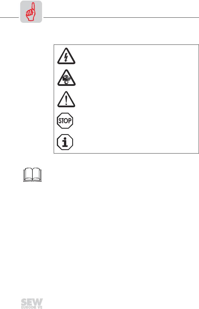
Safety and warn- Always follow the safety and warning instructions contained in this publication! ing instructions
Electrical hazard
Possible consequences: Severe or fatal injuries.
Hazard
Possible consequences: Severe or fatal injuries.
Hazardous situation
Possible consequences: Slight or minor injuries.
Harmful situation
Possible consequences: Damage to the unit and the environment.
Tips and useful information.
Unless the information in the operating instructions is adhered to, it will be impossible to ensure:
•Trouble-free operation
•Fulfillment of any rights to claim under guarantee
Consequently, read the operating instructions before you start working with the unit!
The operating instructions contain important information about servicing. Therefore, keep the operating instructions close to the unit.
Designated use MOVITRAC® 07 frequency inverters operate AC asynchronous motors. These motors must be suitable for operation with frequency inverters. Do not connect any other loads to the frequency inverters.
4 |
|
|
Operating Instructions – MOVITRAC® 07 |
|
|
|
|
|
|
|
|
|
|
|
|

Important Notes |
1 |
|
MOVITRAC® 07 frequency inverters are units intended for stationary installation in switch cabinets. All instructions referring to the technical data and the permissible conditions where the unit is operated must be followed.
Do not start up the unit (take it into operation in the designated fashion) until:
•The machine complies with the EMC Directive 89/336/EEC
•The conformity of the end product has been determined in accordance with the Machinery Directive 89/392/EEC (with reference to EN 60204)
Application envi- |
The following applications are forbidden unless measures are expressly taken to make |
|
ronment |
them possible: |
|
|
• Use in explosion-proof areas |
|
|
• Use in environments with harmful substances: |
|
|
– |
Oils |
|
– |
Acids |
|
– |
Gases |
|
– |
Vapors |
|
– |
Dust |
|
– |
Radiated interference |
|
– |
Other harmful environments |
• Use subject to mechanical vibration and shock loads in excess of the requirements in EN 50178
• If the inverter performs safety functions which have to guarantee the protection of machinery and people
Waste disposal Please follow the current instructions: Dispose in accordance with the regulations in force:
•Electronics scrap (printed-circuit boards)
•Plastic (housing)
•Sheet metal
•Copper
Operating Instructions – MOVITRAC® 07 |
|
|
5 |
|
|
|
|
|
|
|
|
|
|
|
|
2 |
Safety Notes |
|
2 |
Safety Notes |
|
Installation and |
• Never install damaged products or take them into operation. Please submit a |
|
startup |
|
complaint to the transport company immediately in the event of damage. |
•Installation, startup and service work on the unit only by trained personnel. The personnel must be trained in the relevant aspects of accident prevention and must comply with the regulations in force (e.g. EN 60204, VBG 4, DIN-VDE 0100/0113/0160).
•Follow the specific instructions during installation and startup of the motor and the brake!
•Make sure that preventive measures and protection devices correspond to the applicable regulations (e.g. EN 60204 or EN 50178).
Grounding the unit is a necessary protective measure.
Overcurrent protection devices are a necessary protective measure.
•The unit meets all requirements for reliable isolation of power and electronics connections in accordance with EN 50178. All connected circuits must also satisfy the requirements for reliable isolation so as to guarantee reliable isolation.
•Take suitable measures to ensure that the connected motor does not start up automatically when the inverter is switched on. To do this, you can connect binary inputs DI01 through DI03 to GND.
•Connection to the frequency inverter output is only permitted in size 0S, 0M and 0L when the output stage is inhibited.
Operation and |
• Disconnect the unit from the supply system prior to removing the protective |
servicing |
cover. Dangerous voltages may still be present for up to 10 minutes after mains |
|
disconnection. |
•The unit has IP 00 enclosure with the protective cover removed. Dangerous voltages are present at all subassemblies except for the control electronics. Keep the unit closed during operation.
•Dangerous voltages are present at the output terminals and the cables and motor terminals connected to them when the unit is switched on. Dangerous voltages may also be present when the unit is inhibited and the motor at a standstill.
•The unit is not necessarily deenergized when the LEDs and the 7-segment display are off.
•Safety functions inside the unit or a mechanical blockage may cause the motor
to stop. The removal of the source of the malfunction or a reset can result in an automatic restart of the drive. If, for safety reasons, this is not permissible for the driven machine, disconnect the unit from the supply system before correcting the fault.
6 |
|
|
Operating Instructions – MOVITRAC® 07 |
|
|
|
|
|
|
|
|
|
|
|
|

Unit Structure |
3 |
|
Unit design |
||
|
3 Unit Structure
3.1Unit design
Size 0S, 0M, 0L
1
2
3 |
7 |
|
|
8 |
|
|
||
|
9 |
|
4 |
|
|
5 |
10 |
|
6
02978BXX
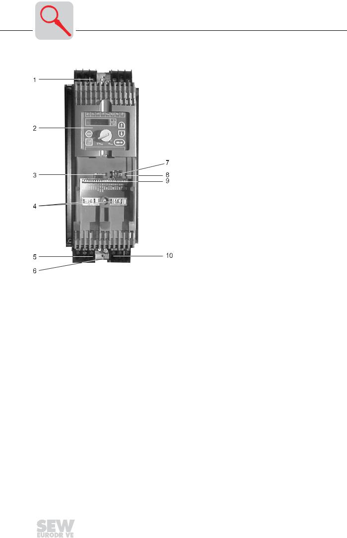
Figure 1: MOVITRAC® 07 unit structure, sizes 0S, 0M, 0L
1.X1: Mains connection 3-phase: L1 / L2 / L3 / PE or 1-phase: L/N/PE
2.Operating panel
3.DIP switch S11 changeover U-signal / I-signal
4.Electronics shield clamp
5.X2: Motor connection U / V / W / PE
6.Power shield clamp
7.X11: RS-485 connection (only for service purposes)
8.DIP switch S12 for system bus terminating resistor
9.X10: Electronics terminal strip
10.X3: Braking resistor connection PE / R+ / R-
Operating Instructions – MOVITRAC® 07 |
|
|
7 |
|
|
|
|
|
|
|
|
|
|
|
|
3 |
Unit Structure |
|
Unit design |
||
|
Size 1, 2S, 2
05132AXX
Figure 2: MOVITRAC® 07 unit structure, sizes 1, 2S, 2
1.X1: Mains connection 3-phase: L1 / L2 / L3 / PE screw
2.Operating panel
3.DIP switch S11 changeover U-signal / I-signal
4.Electronics shield clamp
5.X2: Motor connection U / V / W / PE screw
6.Space for power shield clamp
7.X11: RS-485 connection (only for service purposes)
8.DIP switch S12 for system bus terminating resistor
9.X10: Electronics terminal strip
10.X3: Braking resistor connection R+ / R– / PE
8 |
|
|
Operating Instructions – MOVITRAC® 07 |
|
|
|
|
|
|
|
|
|
|
|
|
Unit Structure |
3 |
|
Unit design |
||
|
Size 3
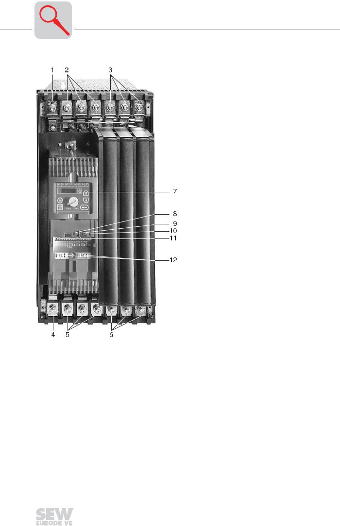
05295AXX
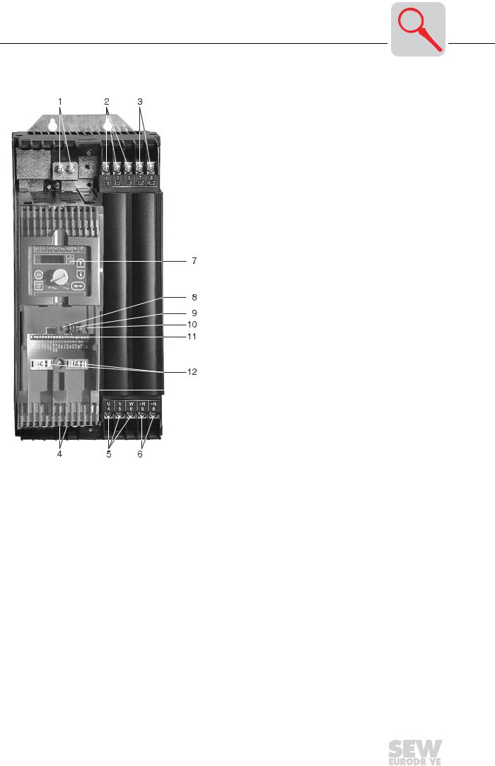
Figure 3: MOVITRAC® 07 unit structure, size 3
1.PE connections
2.X1: Mains connection 3-phase: L1 (1) / L2 (2) / L3 (3)
3.X4: DC link circuit connection (not used)
4.PE connections (not visible)
5.X2: Motor connection U (4) / V (5) / W (6)
6.X3: Braking resistor connection R+ (8) / R– (9)
7.Operating panel
8.DIP switch S12 for system bus terminating resistor
9.X11: RS-485 connection (only for service purposes)
10.DIP switch S11 changeover U-signal / I-signal
11.X10: Electronics terminal strip
12.Electronics shield clamp
Operating Instructions – MOVITRAC® 07 |
|
|
9 |
|
|
|
|
|
|
|
|
|
|
|
|
3 |
Unit Structure |
|
Unit design |
||
|
Size 4
05296AXX
Figure 4: MOVITRAC® 07 unit structure, size 4
1.X2: PE connection
2.X1: Mains connection 3-phase: L1 (1) / L2 (2) / L3 (3)
3.X4: DC link circuit connection (not used)
4.X2: PE connection
5.X2: Motor connection U (4) / V (5) / W (6)
6.X3: Braking resistor connection R+ (8) / R– (9) and PE connection
7.Operating panel
8.DIP switch S12 for system bus terminating resistor
9.X11: RS-485 connection (only for service purposes)
10.DIP switch S11 changeover U-signal / I-signal
11.X10: Electronics terminal strip
12.Electronics shield clamp
10 |
|
|
Operating Instructions – MOVITRAC® 07 |
|
|
|
|
|
|
|
|
|
|
|
|
Unit Structure |
3 |
|
Unit designation and scope of delivery |
||
|
3.2Unit designation and scope of delivery
Sample unit designation
Type MC
Series and generation
Version A
Recommended motor power
Connection voltage
Radio interference suppression
022 = 2.2 kW
2 = 200 ... 240 VAC
5 = 380 ... 500 VAC
B = Radio interference suppression B
A = Radio interference suppression A
0 = No radio interference suppression
Connection type |
3 |
= 3-phase / 1 = 1-phase |
||
Quadrants |
4 |
= 4Q (with brake chopper) |
||
Type |
00 |
= Standard |
||
10 |
= LOGODrive |
|||
|
||||
MC 07 A 004- 2 B 1- 4- 00
Sample nameplate
02940FXX
Figure 5: Sample nameplate
Operating Instructions – MOVITRAC® 07 |
|
|
11 |
|
|
|
|
|
|
|
|
|
|
|
|
3 |
Unit Structure |
|
Unit designation and scope of delivery |
||
|
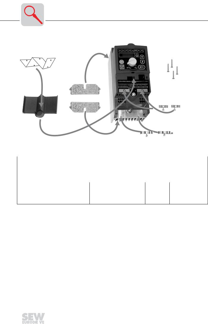
Scope of delivery loose items
5 |
6 |
|
3 |
1 |
|
|
|
|
|
|
|
|
|
2 |
|
Figure 6: Scope of delivery, included loose size 0 |
|
|
|
|
|
|
03000AXX |
||
|
|
|
|
|
|
|
|||
|
|
|
|
|
|
|
|||
|
Scope of delivery, included loose for size |
|
|
||||||
|
0 |
|
1 |
|
2 |
|
3 |
|
4 |
|
|
|
|
|
|||||
• Shield clamps for electronics cables (2 clamps with one screw each) [1] |
|
|
|
|
|||||
• |
Terminal cover [4] |
|
|
|
|
|
|
|
|
• Information label installed on terminal cover [5] |
|
|
|
|
|
||||
|
|
|
|
|
|
|
|||
• |
Shield clamps for motor and brake resis- • |
Power shield clamp with |
|
– |
|
• Touch guard with |
|||
|
tor cables [2] |
retaining screws |
|
|
|
|
retaining screws |
||
•Mounting feet [3]
•Retaining screws for optional braking resistor [6]
12 |
|
|
Operating Instructions – MOVITRAC® 07 |
|
|
|
|
|
|
|
|
|
|
|
|
Installation |
4 |
|
Installation instructions |
||
|
4 Installation
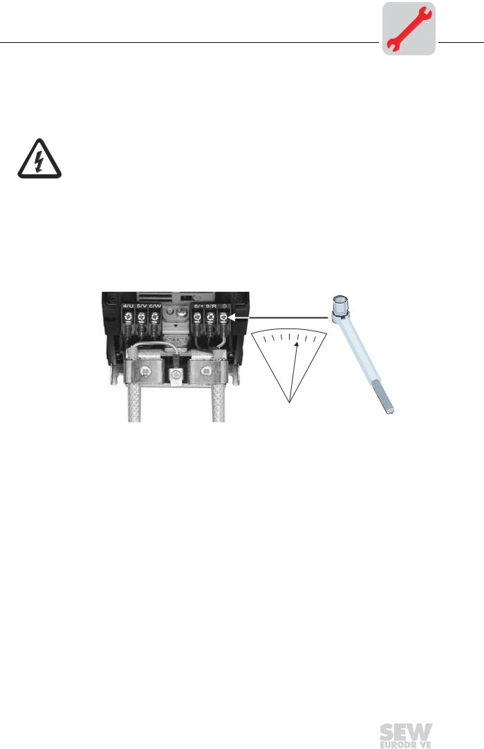
4.1Installation instructions
It is essential to comply with the safety notes during installation!
Tightening |
• Only use genuine connection elements. Note the permitted tightening torques |
||||
torques |
of MOVITRAC® |
07 power terminals. |
|||
|
– |
Size 0S/M/L |
→ |
0.5 |
Nm (4.4 lb.in) |
|
– |
Size 1 |
→ |
0.6 |
Nm (5.3 lb.in) |
|
– |
Size 2S/2 |
→ |
1.5 |
Nm (13.3 lb.in) |
|
– |
Size 3 |
→ |
3.5 |
Nm (31 lb.in) |
|
– |
Size 4 |
→ |
14 Nm (124 lb.in) |
|
Nm (lb.in)!
|
|
02475AXX |
|
Figure 7: Note the tightening torques |
|
Recommended |
• |
Use a screwdriver with a 2.5 mm wide blade for connecting the electronics terminal |
tools |
|
strip X10. |
Conductor end |
• The terminals are provided for installation without conductor end sleeves. |
|
sleeves |
|
|
Minimum clear- |
• |
Leave 100 mm (4 in) clearance at the top and bottom for optimum cooling. No lat- |
ance and mount- |
|
eral clearance required; the units can be lined up side-by-side. Make sure that the |
ing position |
|
circulation of air is not disrupted by cables or other installation materials. Prevent the |
|
|
heated exhaust air from other units from blowing onto this unit. With sizes 4 and 5, |
|
|
do not install any components which are sensitive to high temperatures within 300 |
|
|
mm (11.81 in) of the top of the unit. Only install the units vertically. You must not |
|
|
install them horizontally, tilted or upside down. |
Operating Instructions – MOVITRAC® 07 |
|
|
13 |
|
|
|
|
|
|
|
|
|
|
|
|

4
14
Installation
Installation instructions
Line choke
Separate cable ducts
Input fuses and earth-leakage circuit breakers
PE input connection
IT systems
Contactor
Cross sections
Line lengths for single drives
Unit output
Braking resistor connection
Binary inputs / binary outputs
Interference emission
Shielding and earthing
•When more than four 3-phase units or more than one 1-phase unit are connected to a supply system contactor designed for the total current: Insert a line choke in the circuit to limit the inrush current.
•Route power cables and electronics cables in separate cable ducts.
•Install input fuses at the start of the supply system lead after the supply bus junction. Use type D, DO, NH fuses or power circuit breakers.
Using an earth-leakage circuit breaker as the sole protection device is not permitted. Earth-leakage currents > 3.5 mA can arise during normal operation of the inverter.
•Connect the PE conductor according to the regulations of the country in question. Earth-leakage currents > 3.5 mA can arise during normal operation of the inverter.
•SEW recommends using earth-leakage monitors with a pulse code measuring process in voltage supply systems with a non-earthed star point (IT systems). This avoids mis-tripping of the earth-leakage monitor due to the earth capacitance of the inverter.
•Only use contactors in utilization category AC-3 (IEC 158-1).
•Supply system lead: Cross section according to nominal input current Isystem at rated load
Motor lead: Cross section according to output rated current IN
Electronics cables: Maximum 1.5 mm2 (AWG16) without conductor end sleeves Maximum 1.0 mm2 (AWG17) with conductor end sleeves
The line lengths for size 0 are independent of the PWM frequency. The motor leads for sizes 1 through 4 depend on the frequency. The permitted motor cable lengths are listed in Sec. "Project Planning" of the MOVITRAC® 07 System Manual.
•Only connect an ohmic/inductive load (motor); do not connect a capacitive load!
•Shorten the cables to the required length.
•Binary outputs are short-circuit proof and interference-voltage-proof up to 35 V. They can suffer irreparable damage from higher external voltages!
•Use shielded motor cables or HD output chokes for EMC-compliant installation. This EMC-compliant installation will then comply with EN 55011, class B limit.
•Shield the control cables.
•Connect the shield by the shortest possible route and make sure it is earthed over a wide area.
•Provide high frequency compatible earthing for MOVITRAC® 07 and all additional units (wide area metal-on-metal contact between the heat sink and ground, e.g. unpainted switch cabinet mounting panel).
Operating Instructions – MOVITRAC® 07
Installation |
4 |
|
Installation instructions |
||
|
Line filter |
MOVITRAC® 07 frequency inverters are equipped with an line filter as standard. They |
|
|
comply with the following limit value class to EN 55011 on the line side without further |
|
|
measures: |
|
|
• |
B: 1-phase connection |
|
• |
A: 3-phase connection |
|
|
– 230 V: up to 7.5 kW |
|
|
– 400/500 V: up to 11 kW |
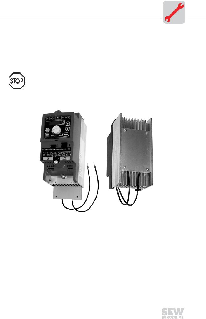
Flat-type braking resistor BW for size 0
No EMC limits are specified for interference emission in voltage supply systems without an earthed star point (IT systems). The effectiveness of line filters is severely limited.
Push the braking resistor in the back of the heat sink. Install the braking resistor in the heat sink with the four screws provided.
03164AXX
Figure 8: Installing the braking resistor BW
Operating Instructions – MOVITRAC® 07 |
|
|
15 |
|
|
|
|
|
|
|
|
|
|
|
|

4 |
Installation |
|
Installation instructions |
||
|
HD output choke • Install the output choke close to MOVITRAC® 07 beyond the minimum clearance.
•Always route all three phases (not the PE!) together through the output choke.
•If the cable is shielded, the shield is not allowed to be routed through the output choke.
02979BXX
Figure 9: Connecting HD output chokes
In the case of the HD output choke, the cable must be wrapped around the choke 5 times.
16 |
|
|
Operating Instructions – MOVITRAC® 07 |
|
|
|
|
|
|
|
|
|
|
|
|

Installation |
4 |
|
UL compliant installation |
||
|
4.2UL compliant installation
Please note the following points for UL compliant installation:
•Only use copper cables with the following temperature ranges as connection leads:
– For MOVITRAC® 07 ... Temperature range 60/75 °C.
•Necessary tightening torques of MOVITRAC® 07 power terminals: See installation notes.
•The inverters are only allowed to be operated on supply systems with a maximum phase-to-earth voltage of 300 VAC.
•The inverter is only allowed to be operated on IT systems if: The phase-to-earth voltage of 300 VAC cannot be exceeded either during operation or in case of a fault.
•The MOVITRAC® 07 frequency inverter is only allowed to be operated on supply systems which can supply maximum values in accordance with the following table. The performance data of the fuses must not exceed the values in the following table.
Maximum values / fuses
230 V units
|
MOVITRAC® 07 |
Max. supply |
Max. supply voltage |
Fuses |
|
|
current |
|
|
|
004/005/008/011/015/022 |
5000 AAC |
240 VAC |
35 A / 250 V |
|
037 |
5000 AAC |
240 VAC |
30 A / 250 V |
|
055/075 |
5000 AAC |
240 VAC |
30 A / 250 V |
|
110 |
5000 AAC |
240 VAC |
175 A / 250 V |
|
150 |
5000 AAC |
240 VAC |
225 A / 250 V |
|
220/300 |
10000 AAC |
240 VAC |
350 A / 250 V |
400/500 V units |
|
|
|
|
MOVITRAC® 07 |
Max. supply cur- |
Max. supply voltage |
Fuses |
|
rent |
|
|
005/008/011 |
5000 AAC |
500 VAC |
15 A / 600 V |
015/022/030/040 |
5000 AAC |
500 VAC |
30 A / 600 V |
055/075 |
10000 AAC |
500 VAC |
30 A / 600 V |
110 |
10000 AAC |
500 VAC |
30 A / 600 V |
150/220 |
5000 AAC |
500 VAC |
175 A / 600 V |
300 |
5000 AAC |
500 VAC |
225 A / 600 V |
Operating Instructions – MOVITRAC® 07 |
|
|
17 |
|
|
|
|
|
|
|
|
|
|
|
|

4 |
Installation |
|
Power shield clamp |
||
|
4.3Power shield clamp
For sizes 1 / 2S SEW-EURODRIVE supplies a power shield clamp as standard with MOVITRAC® 07 size 1 / 2S. Install this power shield clamp together with the retaining screws of the unit.
1 
2
02012BXX
Figure 10: Power shield clamp for MOVITRAC® 07 size 1
1.Shield clamp
2.PE connection (y)
18 |
|
|
Operating Instructions – MOVITRAC® 07 |
|
|
|
|
|
|
|
|
|
|
|
|

Installation |
4 |
|
Touch guard |
||
|
For size 2 |
SEW-EURODRIVE supplies a power shield clamp with two retaining screws as stan- |
|
dard with MOVITRAC® 07 size 2. Install this power shield clamp together with the two |
|
retaining screws on X6. |
01469BXX
Figure 11: Power shield clamp for MOVITRAC® 07 size 2
1.Shield clamp
2.PE connection (y)
Power shield clamps provide you with a very convenient way of installing the shield for the motor and brake leads. Install the shield and PE conductor as shown in the figures.
4.4Touch guard
SEW-EURODRIVE supplies two touch guards with eight retaining screws as standard with MOVITRAC® 07 size 4. Install the touch guard on the two hood covers for the power section terminals.
01470BXX
Figure 12: Touch guard for MOVITRAC® 07 size 4
When the touch guard is installed, MOVITRAC® 07 size 4 has enclosure IP10. The units have IP00 without touch guard.
Operating Instructions – MOVITRAC® 07 |
|
|
19 |
|
|
|
|
|
|
|
|
|
|
|
|

4 |
Installation |
|
Wiring diagram 230 V 0.37 ... 2.2 kW / 400 V 0.55 ... 4.0 kW |
||
|
4.5Wiring diagram 230 V 0.37 ... 2.2 kW / 400 V 0.55 ... 4.0 kW
3 x 230 VAC / PE |
L1 |
|
|
|
|
|
|
|
|
|
|
|
|
|
|
L1 |
|
|
|
|
|
|
|
|
|
|
|
|
||||
L2 |
|
|
|
|
|
|
|
|
|
|
|
|
|
|
N |
|
|
|
|
|
|
|
|
|
|
|
1 x 230 VAC / N / PE |
|||||
|
|
|
|
|
|
|
|
|
|
|
|
|
|
|
|
|
|
|
|
|
|
|
|
|
||||||||
3 x 400/500 VAC / PE |
L3 |
|
|
|
|
|
|
|
|
|
|
|
|
|
|
|
|
|
|
|
|
|
|
|
|
|
||||||
|
|
|
|
|
|
|
|
|
|
|
|
|
||||||||||||||||||||
PE |
|
|
|
|
|
|
|
|
|
|
PE |
|
|
|
|
|
|
|
|
|
|
|
|
|||||||||
F11/F12/F13 |
|
|
|
|
|
|
|
|
|
|
|
|
|
|
|
F11 |
|
|
|
|
|
|
|
|
|
|||||||
|
|
|
|
|
|
|
|
|
|
|
|
|
|
|
|
|
|
|
|
|
|
|
|
|||||||||
|
|
|
|
|
|
|
|
|
|
|
|
|
|
|
|
|
|
|
|
|
|
|
|
|
|
|
|
|
|
|
|
|
K11 |
|
|
|
|
|
|
|
|
|
|
|
|
|
|
|
K11 |
|
|
|
|
|
|
|
|
|
|
|
|
|
|
|
|
|
|
|
|
|
|
|
|
|
|
|
|
|
|
|
|
|
|
|
|
|
|
|
|
|
|
|
|
|
|
|
||
|
|
|
|
|
|
|
|
|
|
|
|
|
|
|
|
|
|
|
|
|
|
|
|
|
|
|
|
|
|
|
||
(AC-3) |
|
|
|
|
|
|
|
|
|
|
|
|
|
|
|
(AC-3) |
|
|
|
|
|
|
|
|
|
|
|
|
|
|
|
|
|
|
|
|
|
|
|
|
|
|
|
|
|
|
|
|
|
|
|
|
|
|
|
|
|
|
|
|
|
|
|||
|
|
|
|
|
|
|
|
|
|
|
|
|
|
|
|
|
|
|
|
|
|
|
|
|
|
|
|
|
|
|
|
|
3-phase |
X1 |
|
|
|
|
|
|
|
|
|
|
|
1-phase |
X1 |
|
|
|
|
|
|
|
|
|
|
|
|
||||||
L1 |
|
L2 |
|
L3 |
|
PE |
|
|
|
|
L |
|
|
N |
|
PE |
|
|||||||||||||||
|
|
|
|
|
|
|
|
|
|
|
|
|
|
|
|
|
|
|
|
|
|
|
|
|
|
|
|
|
|
|
|
|
VAC
F14/F15
K11 (AC-3)
1
2
3 BMK 4
13
14
15
DC and AC disconnect
VAC
F14/F15
DOØ2
K12 (AC-3)
GND
1
BG 2 BGE 34
5
DC and AC disconnection
DOØ2
GND
RD
WH
BU
VAC
F14/F15
|
DOØ2 |
|
|
K12 |
|
|
|
(AC-3) |
|
|
|
|
GND |
|
|
WH |
|
1 |
|
|
|
||
RD |
BG |
2 |
|
3 |
|||
|
BGE |
||
BU |
4 |
||
|
5 |
||
|
|
||
|
AC |
|
|
|
disconnection |
||
|
Toggle switch |
|
|
V* |
|
|
|
|
|
|
|
ON |
|
|
System bus |
||
|
|
|
|
|
|
|
|
|
|
|
|
||||||
I signal |
V signal* |
|
|
|
|
|
|
RS-485 |
|
|
|
|
|
terminating |
|||
|
|
|
|
|
|
|
|
|
|
||||||||
|
|
mA |
|
|
|
|
|
X11 |
|
OFF* |
|
|
resistor |
||||
|
|
|
|
|
|
|
|
|
|
|
|
|
|
||||
|
|
|
S 11 |
|
|
|
|
|
|
|
|
S 12 |
|||||
|
|
|
|
|
|
|
|
|
|
|
|
||||||
VO24 CW/StopDI01 |
CCW/Stop*DI02 |
Enable*DI03 n11/n21*DI04 n12/n22*DI05 VOTF |
|
|
Brake*DOØ2 GND |
|
|
GND |
SC11 SC12 GND |
SC21 |
SC22 GND |
|
|||||
DOØ1- |
Fault* |
|
|
|
|||||||||||||
|
|
|
|
C |
NO-DOØ1 NC-DOØ1 |
|
AI11 |
AI12 |
|
|
|
|
|
|
|
|
|
|
|
|
|
|
|
|
|
+ |
- |
|
|
|
|
|
|
|
|
|
|
|
|
|
|
|
|
|
|
|
|
|
|
|
|
|
|
1 |
2 |
3 |
4 |
5 |
6 |
7 |
8 |
9 |
10 11 12 13 14 15 16 17 18 19 20 21 X10 |
|
|||||||
|
|
|
|
|
|
|
|
|
|
|
|
|
|
|
|
|
|
|
|
|
|
|
|
|
|
|
onK12 |
V |
0...+10V |
busHigh |
busLow |
busHigh |
busLow |
|
|
|
|
|
|
Control |
|
|
|
|
...20mA0(4) |
System |
System |
System |
System |
|
|
||
|
|
|
|
|
|
|
|
|
|
|
|
|
|
|
|||
|
|
|
|
|
|
|
|
|
|
I |
|
|
|
|
|
|
|
|
|
X2 |
U |
|
V |
W |
|
PE |
|
|
|
|
|
|
PE |
+R -R |
X3 |
|
|
|
|
|
|
|
|
|
|
||||||||
|
|
|
|
|
|
|
|
|
|
= Shield clamp |
|
|
|
|
|||
|
|
|
|
|
|
|
|
|
* |
= Factory setting |
|
|
|
|
|||
|
|
|
|
|
|
|
|
|
|
|
|
|
|
|
F16 |
|
|
|
|
|
|
|
|
|
|
|
|
|
|
|
Affects |
|
|
||
WH |
|
|
|
|
|
|
|
|
|
|
|
|
|
|
|||
|
|
|
|
|
|
|
|
|
|
K11 |
|
|
|
BW... |
|||
RD |
|
|
|
|
M |
|
|
|
|
|
|
|
|
|
|
||
|
|
|
|
|
|
|
|
|
|
|
|
|
|
|
|
||
BU |
|
|
3-phase |
|
|
|
|
|
|
|
|
|
P820 |
|
|||
|
|
|
|
|
|
|
|
|
|
|
|
|
|
|
|
|
|
|
|
|
|
|
|
|
|
|
|
|
|
|
|
|
|
= ON! |
|
02943LEN
Figure 13: Wiring diagram for size 0
20 |
|
|
Operating Instructions – MOVITRAC® 07 |
|
|
|
|
|
|
|
|
|
|
|
|
Installation |
4 |
|
Wiring diagram 230 V 3.7 ... 30 kW / 400 V 5.5 ... 30 kW |
||
|
4.6Wiring diagram 230 V 3.7 ... 30 kW / 400 V 5.5 ... 30 kW
3 x 230 VAC / PE |
L1 |
|
|
|
|
|
|
|
|
|
|
|
|
|
|
L2 |
|
|
|
|
|
|
|
|
|
|
|
|
|
||
3 x 400/500 VAC / PE |
L3 |
|
|
|
|
|
|
|
|
|
|
|
|
|
|
|
|
|
|
|
|
|
|
|
|
|
|
|
|||
PE |
|
|
|
|
|
|
|
|
|
||||||
F11/F12/F13 |
|
|
|
|
|
|
|
|
|
|
|||||
|
|
|
|
|
|
|
|
|
|
||||||
K11 |
|
|
|
|
|
|
|
|
|
|
|
|
|
|
|
|
|
|
|
|
|
|
|
|
|
|
|
|
|
|
|
|
|
|
|
|
|
|
|
|
|
|
|
|
|
|
|
|
|
|
|
|
|
|
|
|
|
|
|
|
|
|
|
|
|
|
|
|
|
|
|
|
|
|
|
|
|
|
|
(AC-3) |
|
|
|
|
|
|
|
|
|
|
|
|
|
|
|
|
|
|
|
|
|
|
|
|
|
|
|
|
|
|
|
3-phase |
|
|
|
X1 |
|
|
|
|
|
|
|
|
|
|
|
|
|
|
L1 |
|
L2 |
|
L3 |
|
PE |
||||||
|
|
|
|
|
|
|
|
|
|
|
|
|
|
|
|
Toggle switch  I signal
  V signal*
|
|
|
|
|
S 11 |
|||
|
|
|
|
|
|
|
||
|
DI01CW/Stop DI02CCW/Stop* |
|
DI04n11/n21* |
DI05n12/n22* |
|
DOØ1-C |
|
|
VO24 |
DI03Enable* |
VOTF |
||||||
|
|
|||||||
|
|
|
||||||
V*
mA
NO-DOØ1DOØ1 NC-
Störung*
GND
DOØ2 Brake*
|
|
|
|
|
|
ON |
|
|
System bus |
|
|
|
|
|
|
|
|
||
|
|
|
|
|
|
|
|
terminating |
|
|
|
RS-485 |
|
|
|
|
|
||
|
|
|
|
|
|||||
|
|
|
|
X11 |
|
OFF* |
|
|
resistor |
|
|
|
|
|
|||||
|
|
|
|
|
|
S 12 |
|
||
AI11 |
AI12 |
|
|
|
|
|
|
|
|
+ |
- |
GND |
SC11 SC12 GND SC21 |
SC22 GND |
|
||||
|
|
|
|
|
|
|
|
||
|
1 |
2 |
3 |
4 |
5 |
6 |
7 |
8 |
9 |
10 11 12 13 14 15 16 17 18 19 20 21 X10 |
|
|||||||
VAC |
|
|
|
|
|
|
|
|
|
|
|
|
|
|
|
|
|
|
F14/F15 |
|
|
|
|
|
|
|
|
|
|
|
|
|
|
|
|
|
|
|
|
|
|
|
|
|
|
|
|
|
|
|
|
|
|
|
|
|
K11 |
|
|
|
|
|
|
|
|
|
K12on |
|
...+10V0 |
Highbus |
Lowbus |
Highbus |
Lowbus |
|
|
(AC-3) |
|
|
|
|
|
|
|
|
|
|
|
|
||||||
|
|
|
|
|
|
|
|
|
|
|
|
|
|
|
|
|
|
|
|
|
|
|
|
|
|
|
|
|
|
V |
|
|
|
|
|
|
|
1 |
WH |
|
|
|
|
|
|
|
|
|
|
...20mA0(4) |
System |
System |
System |
System |
|
|
2 |
|
|
|
Control |
|
|
|
|
|
|
||||||||
3 |
DOØ2 |
|
|
|
|
|
|
|
|
|
|
|
|
|
|
|||
BMK 4 |
GND |
|
|
|
|
|
|
|
|
|
|
|
|
|
|
|
|
|
13 |
RD |
|
|
|
|
|
|
|
|
|
I |
|
|
|
|
|
|
|
|
|
|
|
|
|
|
|
|
|
|
|
|
|
|
|
|
||
14 |
BU |
|
|
|
|
|
|
|
|
|
|
|
|
|
|
|
|
|
15 |
|
|
|
|
|
|
|
|
|
|
|
|
|
|
|
|
|
|
AC and DC |
|
|
|
|
|
|
|
|
|
|
|
|
|
|
|
|
|
|
disconnection |
|
|
X2 |
|
|
|
|
|
|
|
|
|
|
|
|
|
|
PE X3 |
VAC |
|
|
U |
|
V |
W |
|
PE |
|
|
|
|
|
+R |
-R |
|||
VAC |
|
|
|
|
|
|
|
|
|
|
|
|
|
|
|
|
|
|
F14/F15 |
|
F14/F15 |
|
= Shield clamp |
|
||
DOØ2 |
|
|
DOØ2 |
|
|
* = Factory setting |
|
|
|
|
|
|
|
|
|
K12 |
|
K12 |
|
|
|
|
F16 |
(AC-3) |
|
(AC-3) |
|
|
|
|
|
GND |
|
|
GND |
|
|
Affects |
|
|
|
WH |
|
|
WH |
|
|
|
1 |
|
1 |
K11 |
BW... |
||
|
|
|
|
||||
BG |
2 |
RD |
BG |
2 |
RD |
M |
|
BGE |
3 |
|
BGE |
3 |
|
3-phase |
|
4 |
BU |
4 |
BU |
P820 |
|||
|
5 |
|
5 |
|
|||
|
|
|
|
|
|||
DC and AC |
|
AC |
|
|
|
= ON! |
|
disconnection |
|
disconnection |
|
|
|
||
|
|
|
|
|
|
05134CEN |
|
Figure 14: Wiring diagram for sizes 1 ... 4
Operating Instructions – MOVITRAC® 07 |
|
|
21 |
|
|
|
|
|
|
|
|
|
|
|
|

4 |
Installation |
|
Wiring diagram 230 V 3.7 ... 30 kW / 400 V 5.5 ... 30 kW |
||
|
Connection of the brake rectifier
A separate supply system lead is required for connecting the brake rectifier; supply from the motor voltage is not permitted!
Only use contactors in utilization category AC-3 (IEC 158-1) for K11 and K12.
Always switch off the brake on the DC and AC sides under the following conditions:
•All hoist applications
•Drives which require a rapid brake reaction time.
When the brake rectifier is installed in the switch cabinet: Route the connecting leads between the brake rectifier and the brake separately from other power cables. Routing together with other cables is only permitted if the other cables are shielded.
Note the corresponding connection regulations for brakes without BG/BGE or BME. Please refer to the publication "Drive Engineering - Practical Implementation, Vol. 4" for detailed information about SEW brakes.
Functional description of the terminals
Terminal |
Function |
|
|
X1 |
L1/L2/L3/PE |
Mains connection |
|
|
L/N/PE |
|
|
|
|
|
|
X2 |
U/V/W/PE |
Motor connection |
|
|
|
|
|
X3 |
PE/+R/-R |
Braking resistor connection |
|
|
|
|
|
X10: |
VO24 |
Auxiliary supply output +24 V (max. 50 mA) |
|
1 |
|||
2 |
DI01 |
Binary input 1, with fixed assignment CW/STOP |
|
3 |
DI02 |
Binary input 2, with factory setting CCW/STOP |
|
4 |
DI03 |
Binary input 3, with factory setting Enable |
|
5 |
DI04 |
Binary input 4, with factory setting n11/n21 |
|
6 |
DI05 |
Binary input 5, with factory setting n12/n22 (TF can only be connected to DI05) |
|
7 |
VOTF |
Voltage supply for TF (PTC thermistor) |
|
8 |
DO01-C |
Binary output 1, factory setting "/Fault" |
|
9 |
DO01-NO |
Binary output 1, NO contact |
|
10 |
DO01-NC |
Binary output 1, NC contact |
|
11 |
DO02 |
Binary output 2, factory setting "Brake released" (Imax = 150 mA) |
|
12 |
GND |
Reference potential |
|
13 |
AI11 |
Analog input 0 ... 10 V / 0(4) ... 20 mA |
|
14 |
AI12 |
|
|
|
|
||
15 |
GND |
Reference potential |
|
16 |
SC11 |
System bus high, incoming |
|
17 |
SC12 |
System bus low, incoming |
|
18 |
GND |
Reference potential |
|
19 |
SC21 |
System bus high, outgoing |
SC21 and SC22 are deactivated when S12 = ON. This |
20 |
SC22 |
System bus low, outgoing |
is necessary in units at the end of the bus. |
21 |
GND |
Reference potential |
|
|
|
|
|
X11 |
RS-485 |
Service interface for UWS21A on PC or parameter module UBP11A |
|
|
|
|
|
22 |
|
|
Operating Instructions – MOVITRAC® 07 |
|
|
|
|
|
|
|
|
|
|
|
|
Installation |
4 |
|
System bus (SBus) installation |
||
|
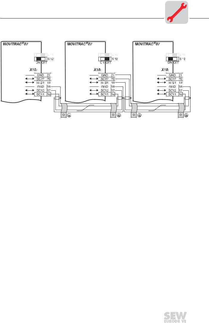
4.7System bus (SBus) installation
05817AXX
Figure 15: MOVITRAC® 07 system bus connection
GND |
= System bus reference |
SC22 |
= System bus low |
SC21 |
= System bus high |
SC12 |
= System bus low |
SC11 |
= System bus high |
S12 |
= System bus terminating resistor |
SBus MOVITRAC 07: Connect the terminating equipment to SC11/SC12. SC21/SC22 are only active when S12 = OFF.
Operating Instructions – MOVITRAC® 07 |
|
|
23 |
|
|
|
|
|
|
|
|
|
|
|
|
5 |
I |
Startup |
|
General startup instructions |
|
|
0 |
|
|
|
5 Startup
Using the IN/OUT key  : Press the key once to go further down into the menu structure (selecting functions). Press twice or use one long key press to change to higher levels in the menu structure.
5.1General startup instructions
It is essential to adhere to the safety notes during startup!
Prerequisite |
Correct project planning of the drive is the prerequisite for successful startup. |
MOVITRAC® 07 frequency inverters are factory set to be taken into operation with the SEW motor which is adapted to the correct power level (4-pole, 50/60 Hz).
You can connect the motor and start the drive immediately.
The startup functions described in this section are used for setting the inverter so it is optimally adapted to the motor which is actually connected and to the given boundary conditions.
5.2Preliminary work and resources
•Check the installation (Installation chapter)).
•Connect the supply system and the motor. Do not connect any signal terminals!
•Switch on the supply system.
•Display shows Stop.
•Program the signal terminals.
•Set the parameters correctly (e.g. factory setting).
• Check the terminal assignment which has been set (→ P60_ (MOVITOOLS) / P60- (display)).
•Switch off the supply system.
•Connect the signal terminals.
•Switch on the supply system.
The inverter automatically changes parameter values when you perform a startup.
24 |
|
|
Operating Instructions – MOVITRAC® 07 |
|
|
|
|
|
|
|
|
|
|
|
|

Startup |
I |
5 |
Integrated operating panel |
|
|
0 |
|
|
|
|
5.3Integrated operating panel
Operation |
The following basic principle applies: Press the |
key once to start editing. Double- |
|
|
click the |
key to exit edit mode. |
|
Functions of the The UP, DOWN and IN/OUT buttons are used for navigating through the menus. The operating panel RUN and STOP/RESET buttons are used for controlling the drive. The setpoint potenti-
ometer is used for selecting setpoints.
"UP" for scrolling through the symbols and editing parameters.
"IN/OUT" for activating and deactivating the symbols or parameter menus
"DOWN" for scrolling through the symbols and editing parameters.
You can start the drive with "RUN".
RUN
"STOP/RESET" is used for resetting faults and for stopping the drive.
STOP
RESET
Stopping the drive with the STOP/RESET key is not a safety function. Switching the power off unlocks the inverter again and you can enable the inverter.
Operating Instructions – MOVITRAC® 07 |
|
|
25 |
|
|
|
|
|
|
|
|
|
|
|
|

5 |
I |
Startup |
|
Principles of operation with the integrated operating panel |
|
|
0 |
|
|
|
5.4Principles of operation with the integrated operating panel
rpm |
A |
n11 |
n12 nmax |
|
Par |
|
|
[rpm] |
|
|
|
|
|
|
[rpm] |
|
|
2x |
|
|
|
|
|
|
[A] |
1x |
|
|
|
|
|
|
|
[s/rpm] |
|
|
|
|
|
|
|
<-2x |
1x-> |
P081 |
<-2x |
1x-> |
[F-00 ... F-99] |
|
|
|
|
||||
|
|
|
|
P100 ... P861 |
<-2x |
1x-> |
[ms/%/...] |
|
|
|
|
|
|
||
|
|
<-2x |
1x-> |
P-01 ... P-05 |
<-2x |
1x-> |
[kW/Hz/...] |
|
|
|
|
||||
|
|
|
|
|
|
|
02968DXX |
Figure 16: Principles of operation with the integrated operating panel (2x = double-click)
26 |
|
|
Operating Instructions – MOVITRAC® 07 |
|
|
|
|
|
|
|
|
|
|
|
|

Startup |
I |
5 |
Principles of operation with the integrated operating panel |
|
|
0 |
|
|
|
|
Available sym- You can select the following symbols using keys  and
and  : bols
Symbol Function |
|||||
|
|
|
|
|
Displays the inverter status or (in "drive enabled" status) the calculated actual speed |
|
rpm |
||||
|
|
|
|
in [rpm] |
|
|
|
|
|
|
|
|
|
|
|
|
|
|
|
|
|
|
Displays the apparent output current in [A] |
|
A |
|
|||
|
|
|
|
|
|
|
|
|
|
|
|
|
|
|
|
|
Sets the accelerating ramp in [s] |
|
|
|
|||
|
|
|
|
|
|
|
|
|
|
|
|
|
|
|
|
|
Sets the deceleration ramp in [s] |
|
|
|
|
||
|
|
|
|
|
|
|
|
|
|
|
|
|
|
|
|
|
Sets the maximum speed in [rpm] |
|
nmax |
|
|
||
|
|
|
|
|
|
|
|
|
|
|
|
|
|
|
|
|
Sets fixed setpoint n11 in [rpm] |
|
n11 |
|
|
||
|
|
|
|
|
|
|
|
|
|
|
|
|
|
|
|
|
Sets fixed setpoint n12 in [rpm] |
|
n12 |
|
|
||
|
|
|
|
|
|
|
|
|
|
|
|
|
|
|
|
|
Motor startup P-01 ... P-05 |
|
|
|
|
||
|
|
|
|
|
|
|
|
|
|
|
|
|
|
|
|
|
Sets the inverter parameters |
|
Par |
|
|
|
|
|
|
|
|
|
|
|
|
|
|
|
|
|
|
|
|
|
Activates the manual speed control module of the operating panel |
|
|
|
|
|
|
|
|
|
|
|
|
Menu system The LED integrated in the symbol lights up when you select a symbol. In the case of symbols which only represent display values, the current display value appears immediately on the 7-segment display.
Editing parameters After selecting the Par |
symbol (display: P---), it is possible to select the required pa- |
|
rameter by selecting |
using |
and . |
Pressing the  key once causes the display to show the number of the required parameter. Press the
  key again to edit the parameter value. If the LED in the corresponding symbol flashes, this indicates the value can now be altered. The value takes effect when you exit edit mode by pressing the
  key twice or about 1 s following the last key press.
Display |
It is possible to select finished combinations for terminal assignment parameters (601 ... |
||
|
604, 620, 621) on the operating panel using parameters 60and 62-. If you set a differ- |
||
|
ent combination with MOVITOOLS, the display shows ----. |
||
Status displays |
The display shows the status if you select the |
|
symbol. The display shows the cal- |
rpm |
|||
|
culated actual speed if the status is "Drive enabled". |
||
|
• Drive "Controller inhibit": dIS (disable) |
||
|
• Drive "No enable": StoP (Stop) |
||
|
• Drive "Enabled": 8888 (actual speed) |
||
|
• Factory settings being reactivated: SEt (Set) |
||
Operating Instructions – MOVITRAC® 07 |
|
|
27 |
|
|
|
|
|
|
|
|
|
|
|
|
5 |
|
|
I |
|
|
Startup |
||
|
|
|
|
|
Manual speed control module and external setpoint selection |
|||
|
|
|
0 |
|
|
|||
|
|
|
|
|
|
|
|
|
|
|
|
|
|
|
|||
|
|
|
|
|
|
|
|
|
|
Fault indication |
If a fault occurs, the display changes to the |
|
symbol and it shows the flashing fault |
||||
|
rpm |
|||||||
|
|
|
|
|
|
code, e.g. F-11 (fault list in Sec. Operation and servicing). |
||
|
Warnings |
Some parameters are not allowed to be altered in all operating states. If you try to do so, |
||||||
|
|
|
|
|
|
the following display appears: r-19 ... r-32. The display shows a code corresponding |
||
to the particular action, e.g. r-28 (controller inhibit necessary). See Sec. Operation and servicing for a list of warnings.
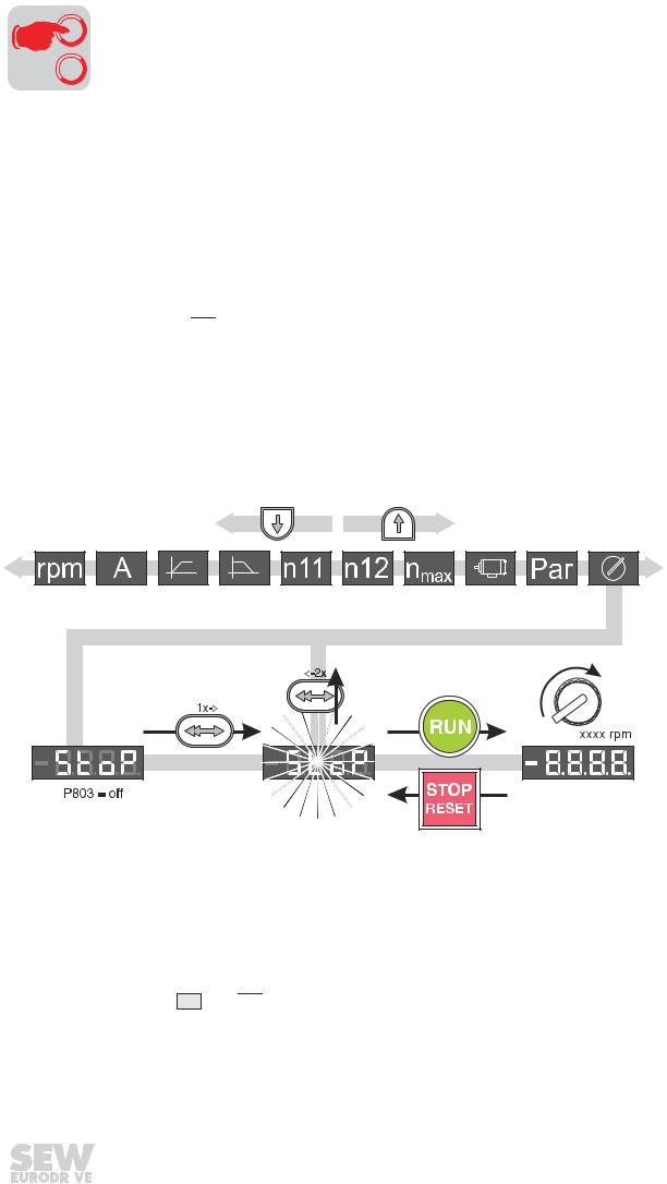
5.5Manual speed control module and external setpoint selection
Manual speed control module of the operating panel (local manual operation): LED flashes 


External setpoint selection
Control via:
–Terminals
–Serial interface
–Setpoint potentiometer on AI11/AI12
Manual speed control module
03158BXX
Figure 17: Manual setpoint adjustment (2x = double-click)
The only relevant parameters in "manual speed control module" operating mode are:
•P122 Local Potentiometer Mode
•"RUN" and "STOP/RESET" buttons
•Setpoint potentiometer
LEDs rpm and  flash when the manual speed control module is activated.
28 |
|
|
Operating Instructions – MOVITRAC® 07 |
|
|
|
|
|
|
|
|
|
|
|
|
Loading...