


T
MOVITRAC® 31C...-503-4-01
Frequency Inverters
Manual
Special Version for Crane Control
Edition 11/96
0922 9868 / 1196

2 |
MOVITRAC ® 31C Crane Control |
|
Phone: 800.894.0412 - Fax: 888.723.4773 - Web: www.clrwtr.com - Email: info@clrwtr.com |

Table of Contents
|
|
|
|
|
|
Page |
|
1 |
Inverter data and installation . . . . . |
. . . . |
. . . . . . |
. . . . . . . . . . . . . . |
. |
. |
4 |
1.1 |
General information and part numbers |
. . . . |
. . . . . . |
. . . . . . . . . . . . . . |
. |
. |
4 |
1.2Differences to the MOVITRAC® 31C basic version . . . . . . . . . . . . . . . . . . . . . 5
1.3Wiring of crane control pushbuttons . . . . . . . . . . . . . . . . . . . . . . . . . . . . 5
1.4Wiring diagram . . . . . . . . . . . . . . . . . . . . . . . . . . . . . . . . . . . . . . . 6
1.5 |
Control inputs . . . . . . . . . . . . . . . . . . . . . . . . . . . . . . . . . . . . . . . |
7 |
1.6 |
Limit switch connection . . . . . . . . . . . . . . . . . . . . . . . . . . . . . . . . . . |
8 |
2 |
Operating instructions . . . . . . . . . . . . . . . . . . . . . . . . . . . . . . . . . . . |
9 |
2.1General . . . . . . . . . . . . . . . . . . . . . . . . . . . . . . . . . . . . . . . . . . . 9
2.2 |
Motorized potentiometer mode |
. . . . . . |
. . . . . . . . . . . . . . . . . . . . |
. . |
. |
. 10 |
2.3 |
Fixed setpoint mode . . . . . . |
. . . . . . |
. . . . . . . . . . . . . . . . . . . . |
. . |
. |
. 12 |
2.4Approach to limit switches (in “motorized potentiometer” mode) . . . . . . . . . . . . . 14
2.5Mode selection while the inverter is running . . . . . . . . . . . . . . . . . . . . . . . . 16
2.6 |
Fault signals . . . . . . . . . . . . . . . . . . . . |
. . . . . . . . . . . . . . . . . . . . 17 |
|
3 |
Additional information (state graphs) . . . . . . |
. . . . . . . . . . . . . . . . . . . . 18 |
|
3.1 |
State graph for the motorized potentiometer mode |
. . . . . . . . . . . . . . . . . . . . 18 |
|
3.2 |
State graph for the fixed setpoint mode . . . . . . . . . . . . . . . . . . . . . . . . . . |
21 |
|
3.3 |
State graph for the preliminary and ultimate limit switches . . . . . . . . . . . . . . . . |
24 |
|
MOVITRAC ® 31C Crane Control |
3 |
Phone: 800.894.0412 - Fax: 888.723.4773 - Web: www.clrwtr.com - Email: info@clrwtr.com |
|

1
Inverter data and installation
1 Inverter data and installation
1.1General information and part numbers
●This supplementary information does not replace the comprehensive Operating Instructions!
●Equipment may only be installed by qualified electrical personnel in compliance with the applicable accident prevention regulations and the MOVITRAC® Operating Instructions.
The power ratings of the MOVITRAC®31C...-503-4-01 special version for crane control are the same as those of the standard version and can be taken from the MOVITRAC® 31C Operating Instructions.
Part numbers of the special version for crane control:
MOVITRAC® type |
Part number |
31C008-503-4-01 |
826 339 6 |
|
|
31C015-503-4-01 |
826 340 X |
|
|
31C022-503-4-01 |
826 341 8 |
|
|
31C030-503-4-01 |
826 342 6 |
|
|
31C040-503-4-01 |
826 343 4 |
|
|
31C055-503-4-01 |
826 344 2 |
|
|
31C075-503-4-01 |
826 345 0 |
|
|
MOVITRAC® type |
Part number |
|
31C110-503-4-01 |
826 399 |
X |
|
|
|
31C150-503-4-01 |
826 400 |
7 |
|
|
|
31C220-503-4-01 |
826 401 |
5 |
|
|
|
31C300-503-4-01 |
826 402 |
3 |
|
|
|
31C370-503-4-01 |
826 403 |
1 |
|
|
|
31C450-503-4-01 |
826 404 |
X |
|
|
|
|
|
|
The special versions for crane control are fitted with the FEA 31C input/output expansion pcb. This option pcb carries the system EPROMs for crane control.
The system EPROMs for the crane control option have the part numbers: 822 246 0.XX LOW 822 247 9.XX HIGH
Functions like hoist and speed control etc. continue to be available without any restrictions.
4 |
MOVITRAC ® 31C Crane Control |
|
Phone: 800.894.0412 - Fax: 888.723.4773 - Web: www.clrwtr.com - Email: info@clrwtr.com |

Inverter data and installation
1.2Differences to the MOVITRAC® 31C basic version
MOVITRAC® 31C...-503-4-01 inverters are especially equipped for applications such as trolleys for bridge cranes and hoists.
● Two operating modes are implemented.
The signal level on input TL. 34/35 determines which of the two operating modes is active:
TL. 34 |
0...5 V |
= “0" |
motorized potentiometer mode |
(ground control) |
|
7.5...30 V |
= ”1" |
fixed setpoint mode |
(radio control) |
TL. 35 |
jumper with TL. 30 (0V24) |
|
||
●A comprehensive limit switch control monitors the preliminary and ultimate (operational) limit switches along the distance of travel of the bridge crane or trolley. To this end, the binary inputs TL. 48/49/50/51 are permanently assigned to limit switch monitoring (low active). Parameters P603...P606 are therefore ineffective.
●External fault detection via TL. 36/37:
The analogue input is used for an “external fault” binary input signal, which is active when low.
TL. 36 |
0...5 V |
= “0" |
external fault |
|
7.5...30 V |
= ”1" |
no fault |
TL. 37 |
jumper to TL. 30 |
|
|
Note: |
If this signal input is not used, then TL. 36 - TL. 44 (+24V) and TL. 37 - TL. 30 must |
||
|
be jumpered |
|
|
●The following functions of the standard version are no longer available:
-manual operation (P 87_)
-master/slave operation (P 88_)
-setpoint n1 TL. 32/33 with standard function
-setpoint n2 TL. 34/35
-external current limit TL. 36/37
-programming capability of the binary inputs TL. 42-51 (P 60_)
-all functions, activated through binary inputs Exception: fixed setpoints
parameter set selection
-reset via binary input
1.3Wiring of crane control pushbuttons
CW
CCW
|
42 |
|
41 |
|
43 |
|
|
44 |
|
CCW |
CW |
Motorized |
+24 V |
||||||
Fig. 1: Wiring of crane control pushbuttons |
|
potentiometer |
|
|
00584AEN |
||||
|
|
|
|
|
|
||||
MOVITRAC ® 31C Crane Control
Phone: 800.894.0412 - Fax: 888.723.4773 - Web: www.clrwtr.com - Email: info@clrwtr.com
1
5
1
Inverter data and installation
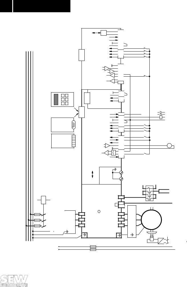
1.4Wiring diagram
|
|
|
|
|
|
|
|
RS 485 |
|
68 |
|
|
|
|
|
|
|
|
|
|
|
67 |
|
||
|
|
|
|
|
|
|
|
|
|
|
|
|
|
|
|
|
|
|
|
|
0/1= I |
* |
|
64 |
|
|
|
|
|
|
|
|
|
|
Ref |
|
63 |
|
|
|
|
|
|
|
|
|
1/0=healthy/Ixt warning* |
|
|
||
|
|
|
|
|
|
|
|
|
0V24 |
|
30 |
2) |
|
|
|
|
|
|
|
|
Ref. 48-51 |
|
60 |
||
|
|
|
|
|
|
|
|
|
|
|||
|
|
|
|
X20: |
|
CCW preliminary limit switch |
|
51 |
|
|||
|
|
|
|
*Factorysetting |
|
CCW ultimate limit switch |
|
X8: |
|
|||
|
|
|
|
|
|
|
|
|
50 |
|
||
|
|
|
|
|
|
|
CW preliminary limit switch |
|
49 |
|
||
|
|
|
|
|
|
|
|
CW ultimate limit switch |
|
48 |
|
|
|
|
|
|
|
|
|
|
|
0V10 |
|
0 |
|
|
|
|
|
|
|
|
|
Output current* |
|
|
39 |
|
|
|
|
|
|
|
|
|
Output frequency* |
|
38 |
|
|
|
|
|
|
|
|
|
|
External fault |
|
+- |
37 |
|
|
|
|
|
|
|
|
|
|
36 |
|
||
|
|
|
|
31C |
|
|
No function |
|
-+ |
|
||
|
|
|
|
|
|
|
33 |
|
||||
|
|
|
|
FEA |
|
|
|
|
|
32 |
|
|
|
|
|
|
|
|
|
|
|
X7: |
|
||
|
|
|
|
|
|
|
|
|
0V24 |
|
30 |
2) |
|
|
FBG31C |
Keypad option |
|
|
X21: |
Ref. 48/49 |
|
60 |
|||
|
|
|
|
CW preliminary limit switch |
|
X14: |
||||||
|
|
|
|
|
|
|
|
|
49 |
|
||
|
|
|
|
|
|
|
|
CW ultimate limit switch |
|
48 |
|
|
|
|
|
|
X4: |
|
|
|
1/0 = fault free/fault * |
|
62 |
|
|
|
|
|
|
|
|
|
|
Brake |
|
61 |
|
|
USS11A |
-(RS232) |
interface option |
X11: |
|
|
|
|
|
0V24 |
|
30 |
3)2) |
|
|
eration or setpoint selection 1 |
|
43 |
||||||||
|
|
|
|
|
|
|
|
Ref. 41-47 |
|
60 |
|
|
|
|
|
|
|
|
|
|
Parameter set selection |
|
47 |
|
|
|
|
|
|
|
|
|
|
or setpoint selection 2 |
|
|
||
|
|
|
|
|
|
Motorized potentiometer accel- |
|
|
|
|||
|
|
|
|
setting |
|
|
|
1/0= CCW/ Stop* |
|
42 |
|
|
|
-(RS485) |
|
|
|
|
|
1/0= CW/ Stop |
|
X3: |
|
||
UST11A |
interface option |
X11: |
Factory* |
|
|
|
|
41 |
|
|||
|
|
Output frequency* |
+24V |
|
65 |
|
||||||
|
|
|
|
|
|
|
|
|
|
44 |
|
|
|
|
|
|
|
|
|
|
+24V (external) |
|
40 |
|
|
|
|
|
|
|
Measurement output |
0V10 |
|
0 |
|
|||
|
|
|
|
|
|
|
|
|
|
|
||
|
|
|
|
|
|
|
|
|
|
|
|
|
K11
F11/F12/F13
|
|
|
|
NDlinechokeoption |
(if4ormoreunitsareconnectedviaacontactor) |
|
|
|
|
|
|
|
|||
|
|
|
|
|
|||
|
|
|
|
|
|
|
|
|
|
|
W1 |
|
|
W2 |
|
|
|
|
|
|
|
||
|
|
|
|
|
|
|
|
|
|
|
V1 |
|
|
V2 |
|
|
|
|
|
|
|
|
|
|
|
|
U1 |
|
|
U2 |
|
|
|
|
|
|
|
|
|
|
|
|
|
|
|
|
|
L1 L2 L3
NF... mains input filter option
L1' L2' L3'
|
Mode selection |
+- |
|
|
|
+10V (3mA) |
|
Processorpcb |
S1 |
left right Isignal Vsignal |
Screenplate |
Powersection |
|
31C |
|
|
|
R |
|
3 |
MOVITRAC |
X1: |
|
2 |
|
1 |
|
S1 |
35 |
|
|
34 |
3) |
||
|
|||
|
31 |
||
|
|
X2:
X0:
9 |
z |
8 |
1) |
|
|
|
+U |
8 |
7/V5 |
|
|
|
X1: |
6 |
|
6/W15/V14/U1 |
optionfilteroutput...HF |
W/W2V/V2U/U2 |
|
|
|
|
|
|
|
5 |
|
|
|
|
|
4 |
|
|
|
|
|
|
|
PE |
|
PE |
L1 L2 L3 PE |
AC |
F14/F15 |
|
U |
|
Fig. 2: Wiring diagram
+24V |
S20 |
|
|
|
|
|
|
|
|
|
|
|
|
|
|
|
|
|
|
|
|
|
|
|
|
|
|
|
|
|
|
|
S19 |
|
|
|
|
|
|
|
|
|
|
|
|
|
|
|
S18 |
|
|
|
|
|
|
|
|
|
|
|
|
|
|
|
S17 |
|
|
|
factoryJumpers,installed;connectbinary |
internalwithref.inputgroundofunit |
|
|
|
|
|
|
|
|
|
|
S16 |
|
|
|
|
|
seeselectionModeSec.2.5 |
|
|
|
|
||||
|
|
|
|
|
|
|
|
|
|
|
|
|
|
|
|
|
|
|
|
2) |
|
|
3) |
|
|
|
|
||||
|
S15 |
K12 |
|
Binaryoutputsignals |
forPLCorexternal outputrelay; |
TL.61:max.150mA/3.6W TL.62:max.50mA/1.2W (alternatively:contactorK12 |
forbrakeoperation) |
|
|||||||
|
|
|
|||||||||||||
|
|
|
|||||||||||||
|
S14 |
|
|
|
|
|
|
|
|
|
|
|
|
|
|
|
S13 |
|
|
|
|
|
|
|
|
|
|
|
|
|
|
|
S12 |
|
|
|
|
|
|
|
|
|
|
|
|
|
|
|
PWM signal TTL |
|
V |
|
|
|
|
|
|
|
|
||||
|
S11 |
|
|
|
|
|
|
|
|
Connection TL.-503...-HF-8TL.V5 |
|
forpermissibleOnlyPWM |
andkHz12frequencyhigher |
||
|
|
|
|
|
|
|
|
|
|
|
|
|
|
|
|
|
|
|
|
|
|
|
|
|
|
|
|
|
|
||
|
effectsK11 |
|
|
|
|
|
|
|
|
Kl.8 |
|
|
1x/2x |
||
|
|
|
|
|
|
|
|
|
|
|
|
||||
F16 |
BW... |
|
|
|
|
|
|
Type |
|
MC31C005- |
MC31C450 |
||||
|
|
|
|
|
|
|
|
1) |
|
|
|
|
|||
|
|
|
|
|
|
|
|
|
|
|
|
||||
M |
3phas. |
|
|
|
K12 |
|
|
|
|
|
0V10(Referencepotential10V,analoguesignals) |
|
0V24(Referencepotential24V,binarysignals) |
Protectiveearthconductor(screen) |
|
|
|
|
|
|
|
||||||||||
|
|
= |
|
|
|
|
|
|
|
|
|
|
|
|
|
|
|
|
|
|
|
|
|
|
|
|
|
|
|
|
|
|
|
~ |
|
|
|
|
|
|
|
|
|
|
|
|
|
|
|
|
|
|
|
|
|
|
|
|
TL.0 |
|
Kl.30 |
Strip |
|
|
|
|
|
|
|
|
|
||||||||
00556AEN
Terminals X14:48 - X8:48 and X14:49 - X8:49 are OR’d internally, allowing terminals X14:48-49 or X8:48-49 to be used alternatively.
An external voltage +24V can be applied directly to analogue inputs X2:34 and X7:36. The negative output of the external power supply must be connected to 0V24 (TL. 30).
6 |
MOVITRAC ® 31C Crane Control |
|
Phone: 800.894.0412 - Fax: 888.723.4773 - Web: www.clrwtr.com - Email: info@clrwtr.com |

Inverter data and
1
installation
1.5Control inputs
1.Motorized potentiometer mode (for ground control) = control by modified motorized potentiometer function. The motorized potentiometer function (P15_) of the MOVITRAC® is automatically activated
Terminal |
Function |
Signal status “1" |
Signal status ”0" |
|
|
|
|
TL. |
Mode selection |
Fixed setpoint mode |
Motorized potentiometer mode |
34/35 |
|
|
|
|
|
|
|
TL. |
External fault detection |
No fault |
External fault |
36/37 |
(e.g. TF thermistor) |
|
|
|
|
|
|
TL. 41 |
Enable + CW |
Ramp UP t11* (P120) to fmin |
Ramp DOWN t4 (P 152) to fmin |
|
|
|
Ramp DOWN t11* (P 121) to fstart/stop |
|
|
|
|
TL. 42 |
Enable + CCW |
Ramp UP t11* (P 120) to fmin |
Ramp DOWN t4 (P 152) to fmin |
|
|
|
Ramp DOWN t11* (P 121) to fstart/stop |
|
|
|
|
TL. 43 |
Acceleration motorized |
Ramp UP t4 (P 151) to fmax |
Setpoint stays at present value |
|
potentiometer |
|
|
|
|
|
|
TL. 47 |
Parameter selection* |
Parameter set 2 |
Parameter set 1 |
|
|
|
|
TL. 48 |
CW ultimate limit switch |
|
CW ultimate limit switch reached |
|
|
|
→ rapid stop ramp t13* (P140), |
|
|
|
output stage inhibited, brake applied |
|
|
|
|
TL. 49 |
CW preliminary limit |
|
CW preliminary limit switch reached |
|
switch |
Status during travel |
→ rapid stop ramp t13* to fmin |
|
|
|
|
TL. 50 |
CCW ultimate limit |
|
CCW ultimate limit switch reached |
|
switchtravel |
|
→ rapid stop ramp t13*, output stage |
|
|
|
inhibited, brake applied |
|
|
|
|
TL.51 |
CCW preliminary limit |
|
CCW preliminary limit switch reached |
|
switch |
|
→ rapid stop ramp t13* to fmin |
|
|
|
|
* The parameters of the 2nd parameter set are activated through the parameter set selection parameter.
2. Fixed setpoint mode (for radio control) = control by internal fixed setpoints
Terminal |
Function |
Signal status “1" |
Signal status ”0" |
|
|
|
|
TL. 34/35 |
Mode selection |
Fixed setpoint mode |
Motorized potentiometer mode |
|
|
|
|
TL. 36/37 |
External fault detection |
No fault |
External fault |
|
(e.g. TF thermistor) |
|
|
|
|
|
|
TL. 41 |
Enable + CW |
Ramp UP t11 (P 120) to fmin |
Ramp DOWN t11 (P 121) to fmin |
|
|
|
Ramp DOWN t13 (P 140) to fstop |
|
|
|
|
TL. 42 |
Enable + CCW |
Ramp UP t11 (P 120) to fmin |
Ramp DOWN t11 (P 121) to fmin |
|
|
|
Ramp DOWN t13 (P 140) to fstop |
|
|
|
|
TL. 43 |
Internal fixed setpoint n11 |
n11 active |
n11 ineffective |
|
|
|
|
TL. 47 |
Internal fixed setpoint n12 |
n12 active |
n12 ineffective |
|
|
|
|
TL. 43+47 |
Internal fixed setpoint n13 |
n13 active |
n13 ineffective |
|
|
|
|
TL. 48-51 |
Ultimate and preliminary |
See table above |
|
|
limit switches |
|
|
|
|
|
|
If not all limit switch inputs (TL. 48/49/50/51) are used, the open inputs must be connected to +24V (TL. 44) as otherwise the limit switch monitoring will signal a fault (→ Sec. 2.6 Fault signals).
MOVITRAC ® 31C Crane Control |
7 |
Phone: 800.894.0412 - Fax: 888.723.4773 - Web: www.clrwtr.com - Email: info@clrwtr.com |
|
1
Inverter data and installation
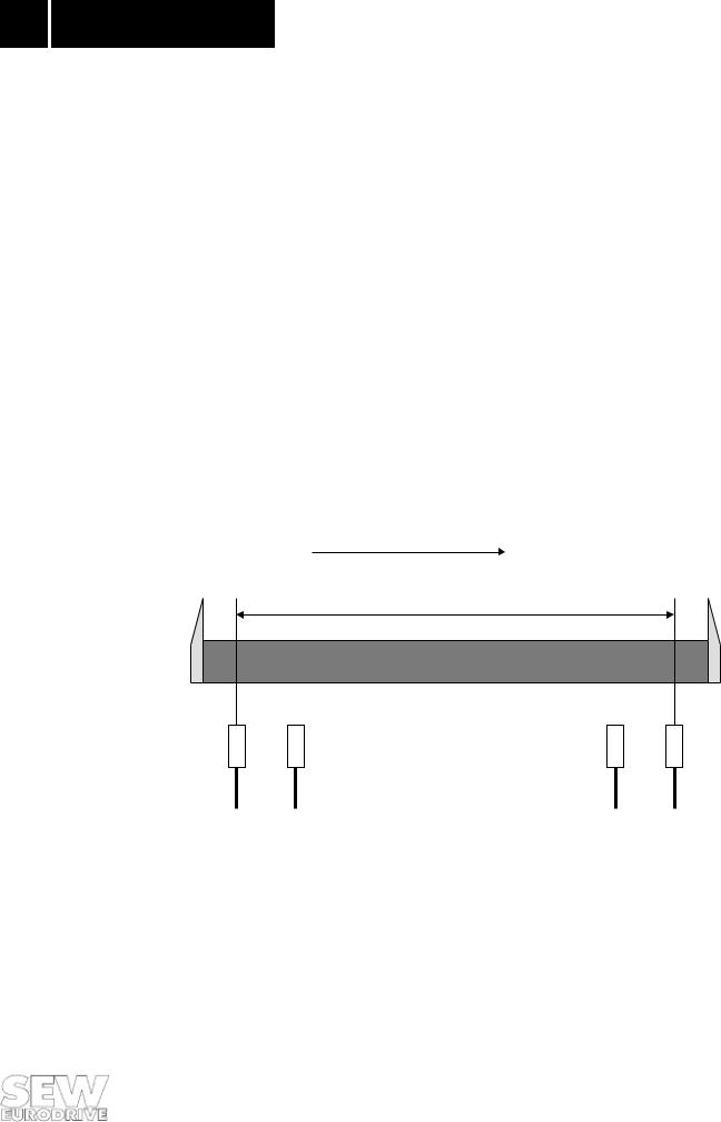
1.6Limit switch connection
The use of end-of-track limit switches for crane control is supported. Altogether four limit switch inputs are available for monitoring the travel and the travel speed. ( → Sec. 1.4 Wiring diagram and Sec. 1.5 Control inputs).
- CW ultimate limit switch |
TL. 48 |
|
- CW preliminary limit switch |
TL. 49 |
|
- |
CCW ultimate limit switch |
TL. 50 |
- |
CCW preliminary limit switch |
TL. 51 |
The limit switches must be installed along the distance of travel in accordance with Fig. 4. For safety reasons the limit switches must be implemented as “low active”. When the inverter is enabled the internal limit switch monitoring feature monitors whether both preliminary and ultimate limit switches are connected in accordance with the wiring diagram (→ Sec. 1.4). If only one of the two preliminary or ultimate limit switches is missing no fault signal is issued. The limit switches are not monitored for correct connection.
If not all limit switch inputs (TL. 48/49/50/51) are used, the open inputs must be connected to +24V (TL. 44) otherwise the limit switch monitoring will issue a fault signal (→ Sec. 2.6 Fault signals).
CW frequency inverter
Distance of travel |
CCWultimatelimitswitch |
CCWpreliminarylimitswitch |
CWpreliminarylimitswitch |
CWultimatelimitswitch |
Fig. 3: Limit switch installation |
|
00557AEN |
|
8 |
MOVITRAC ® 31C Crane Control |
|
Phone: 800.894.0412 - Fax: 888.723.4773 - Web: www.clrwtr.com - Email: info@clrwtr.com |
 Loading...