


Gearmotors \ Industrial Gear Units \ Drive Electronics \ Drive Automation \ Services
|
|
|
|
|
|
|
|
|
|
|
|
|
|
|
|
|
|
|
|
|
|
|
|
|
|
|
|
|
|
|
|
|
|
|
|
|
|
|
|
|
|
|
|
|
|
|
|
|
|
|
|
|
|
|
|
|
|
|
|
|
|
|
|
|
|
|
|
|
|
|
|
|
|
|
|
|
|
|
|
|
|
|
|
|
|
|
|
|
|
|
|
|
|
|
|
|
|
|
|
|
|
|
|
|
|
|
|
|
|
|
|
|
|
|
|
|
|
|
|
|
|
|
|
|
|
|
|
|
|
|
|
|
|
|
|
|
|
|
|
|
|
|
|
|
|
|
|
|
|
|
|
|
|
|
|
|
|
|
|
|
|
|
|
|
|
|
|
|
|
|
|
|
|
|
|
|
|
|
|
|
|
|
|
|
|
|
|
|
|
Fieldbus Interface DFP21B |
|
|
|
|
|
|
|
|
|
FA375100 |
||||||||
PROFIBUS DP-V1 |
|
|
|
|
|
|
|
|
|
|
|
|
|
|
|
|
|
|
Edition 07/2006 |
Manual |
|||||||||||||||||
11479019 / EN |
||||||||||||||||||
|
|
|
|
|
|
|
|
|
|
|
|
|
|
|
|
|
|
|
|
|
|
|
|
|
|
|
|
|
|
|
|
|
|
|
|
|
|

SEW-EURODRIVE – Driving the world
Phone: 800.894.0412 - Fax: 888.723.4773 - Web: www.clrwtr.com - Email: info@clrwtr.com

|
|
|
|
|
|
|
|
|
|
|
|
|
|
|
|
|
|
|
|
|
|
|
|
|
|
|
|
|
|
|
|
|
|
|
|
|
|
|
|
|
|
|
|
|
|
|
|
|
|
|
|
|
|
|
|
|
|
|
|
|
|
|
|
|
|
|
|
|
|
|
|
|
|
|
|
|
|
|
|
|
|
|
|
|
|
|
|
|
|
|
|
|
|
|
|
|
|
|
|
|
|
|
|
|
|
|
|
|
|
|
|
|
|
|
|
|
|
|
|
|
|
|
|
|
|
|
|
|
|
|
|
|
|
|
|
......................................................................................................1 Important Notes |
6 |
||||||
1.1 |
Explanation of symbols .................................................................................. |
6 |
|||||
1.2 |
Part of the product ......................................................................................... |
6 |
|||||
1.3 |
Documentation reference............................................................................... |
6 |
|||||
1.4 |
Liability for defects ......................................................................................... |
7 |
|||||
1.5 |
Product names and trademarks..................................................................... |
7 |
|||||
1.6 |
Disposal ......................................................................................................... |
7 |
|||||
2 Safety Notes ........................................................................................................... |
8 |
|
2.1 |
Preliminary information .................................................................................. |
8 |
2.2 |
General safety notes...................................................................................... |
8 |
|
2.2.1 General safety notes for bus systems.................................................. |
8 |
2.3 |
Transport / storage......................................................................................... |
8 |
2.4 |
Installation / assembly.................................................................................... |
9 |
2.5 |
Startup / operation ......................................................................................... |
9 |
3 Introduction .......................................................................................................... |
10 |
||
3.1 |
Content of the manual.................................................................................. |
10 |
|
3.2 |
Additional documentation............................................................................. |
10 |
|
3.3 |
Features....................................................................................................... |
10 |
|
|
3.3.1 MOVIDRIVE®, MOVITRAC® B and PROFIBUS................................ |
10 |
|
|
3.3.2 Access to all information.................................................................... |
11 |
|
|
3.3.3 Cyclical and acyclical data exchange via PROFIBUS DP ................. |
11 |
|
|
3.3.4 |
Acyclical data exchange via PROFIBUSDP-V1................................. |
11 |
|
3.3.5 |
Configuring the PROFIBUS option card ............................................ |
12 |
|
3.3.6 |
Monitoring functions........................................................................... |
12 |
|
3.3.7 |
Diagnostics ........................................................................................ |
13 |
|
3.3.8 |
Fieldbus monitor ................................................................................ |
13 |
4 Assembly and Installation Notes ........................................................................ |
14 |
||
4.1 |
Installing the DFP21B option card in MOVIDRIVE® MDX61B ..................... |
14 |
|
|
4.1.1 |
Before you start ................................................................................. |
14 |
|
4.1.2 Installing and removing an option card .............................................. |
15 |
|
4.2 |
Installing the DFP21B option card in MOVITRAC® B .................................. |
16 |
|
|
4.2.1 |
SBus connection................................................................................ |
16 |
|
4.2.2 |
System bus connection...................................................................... |
17 |
4.3 |
Assembling and installing the UOH11B gateway housing ........................... |
18 |
|
4.4 |
Connection and terminal description of the DFP21B option ........................ |
20 |
|
4.5 |
Pin assignment ............................................................................................ |
21 |
|
|
4.5.1 MOVIDRIVE® / MOVITRAC® B / PROFIBUS connection ................. |
21 |
|
|
4.5.2 |
Baud rates greater than 1.5 MBaud................................................... |
21 |
4.6 |
Shielding and routing bus cables ................................................................. |
22 |
|
4.7 |
Bus termination ............................................................................................ |
22 |
|
4.8 |
Setting the station address .......................................................................... |
23 |
|
4.9 |
Operating mode displays: option DFP21B................................................... |
24 |
|
|
4.9.1 PROFIBUS LEDs............................................................................... |
24 |
|
Phone: 800.894.0412 - Fax: 888.723.4773 - Web: www.clrwtr.com - Email: info@clrwtr.com
Manual – Fieldbus Interface DFP21B PROFIBUS DP-V1 |
|
|
3 |
|
|
|
|
|
|
|
|
|
|
|
|

|
|
|
|
|
|
|
|
|
|
|
|
|
|
|
|
|
|
|
|
|
|
|
|
|
|
|
|
|
|
|
|
|
|
|
|
|
|
|
|
|
|
|
|
|
|
|
|
|
|
|
|
|
|
|
|
|
|
|
|
|
|
|
|
|
|
|
|
|
|
|
|
|
|
|
|
|
|
|
|
|
|
|
|
|
|
|
|
|
|
|
|
|
|
|
|
|
|
|
|
|
|
|
|
|
|
|
|
|
|
|
|
|
5 Project Planning and Startup |
26 |
||
|
|
|
|
|
||||
|
|
|
|
|
||||
|
|
|
|
|
||||
|
|
|
|
|
||||
|
|
|
|
|
||||
5.1 |
Validity of the GSD files for DFP21B............................................................ |
26 |
||||||
5.2 |
DP master project planning the with MOVIDRIVE® GSD file....................... |
26 |
||||||
|
|
|
|
|
|
5.2.1 |
GSD file for PROFIBUSDP................................................................ |
26 |
|
|
|
|
|
|
5.2.2 |
GSD file for PROFIBUSDP-V1 .......................................................... |
27 |
|
|
|
|
|
|
5.2.3 |
Project planning procedure................................................................ |
28 |
|
|
|
|
|
|
5.2.4 |
DP configuration for MOVIDRIVE® MDX61B (SEWA6003.GSD)...... |
29 |
|
|
|
|
|
|
5.2.5 |
MOVIDRIVE® MDX61B external diagnostics .................................... |
32 |
5.3 |
DP master project planning with MOVITRAC® or gateway GSD file ........... |
34 |
||||||
|
|
|
|
|
|
5.3.1 |
GSD files for operation in MOVITRAC® B and UOH11B gateway |
|
|
|
|
|
|
|
|
housing .............................................................................................. |
34 |
|
|
|
|
|
|
5.3.2 |
PROFIBUS DP master startup........................................................... |
35 |
|
|
|
|
|
|
5.3.3 Configuration of the PROFIBUSDP interface .................................... |
36 |
|
|
|
|
|
|
|
5.3.4 Autosetup for gateway operation ....................................................... |
40 |
|
5.4 |
Setting the MOVIDRIVE® MDX61B drive inverter ....................................... |
42 |
||||||
5.5 |
Setting the MOVITRAC® frequency inverter ................................................ |
43 |
||||||
6 PROFIBUS DP Operating Characteristics ......................................................... |
45 |
||
6.1 |
Controlling the MOVIDRIVE® MDX61B drive inverter ................................. |
45 |
|
|
6.1.1 |
Control example for SIMATIC S7 with MOVIDRIVE® MDX61B ........ |
46 |
|
6.1.2 PROFIBUS DP timeout (MOVIDRIVE® MDX61B)............................. |
46 |
|
|
6.1.3 |
Fieldbus timeout response (MOVIDRIVE® MDX61B)........................ |
46 |
6.2 |
Control of the MOVITRAC® inverter (gateway)............................................ |
47 |
|
|
6.2.1 |
Control example for SIMATIC S7 with MOVITRAC® B (gateway)..... |
48 |
|
6.2.2 |
SBus timeout ..................................................................................... |
48 |
|
6.2.3 |
Unit faults........................................................................................... |
48 |
|
6.2.4 Fieldbus timeout of the DFP21B in gateway operation...................... |
49 |
|
6.3 |
Parameter settings via PROFIBUS DP........................................................ |
49 |
|
|
6.3.1 Structure of the 8-byte MOVILINK® parameter channel .................... |
49 |
|
|
6.3.2 |
Reading a parameter with PROFIBUS DP (READ)........................... |
52 |
|
6.3.3 |
Writing a parameter via PROFIBUS DP (WRITE) ............................. |
53 |
|
6.3.4 |
Parameter setting procedure with PROFIBUS DP............................. |
54 |
|
6.3.5 |
Parameter data format....................................................................... |
54 |
6.4 |
SIMATIC STEP7 program example ............................................................. |
55 |
|
6.5 |
Return codes for parameter setting.............................................................. |
56 |
|
|
6.5.1 |
Elements............................................................................................ |
56 |
|
6.5.2 |
Error class.......................................................................................... |
56 |
|
6.5.3 |
Error code .......................................................................................... |
56 |
|
6.5.4 |
Additional code .................................................................................. |
57 |
6.6 |
Special cases............................................................................................... |
57 |
|
|
6.6.1 |
Special return codes .......................................................................... |
57 |
Phone: 800.894.0412 - Fax: 888.723.4773 - Web: www.clrwtr.com - Email: info@clrwtr.com
4 |
Manual – Fieldbus Interface DFP21B PROFIBUS DP-V1 |
|
|

|
|
|
|
|
|
|
|
|
|
|
|
|
|
|
|
|
|
|
|
|
|
|
|
|
|
|
|
|
|
|
|
|
|
|
|
|
|
|
|
|
|
|
|
|
|
|
|
|
|
|
|
|
|
|
|
|
|
|
|
|
|
|
|
|
|
|
|
|
|
|
|
|
|
|
|
|
|
|
|
|
|
|
|
|
|
|
|
|
|
|
|
|
|
|
|
|
|
|
|
|
|
|
|
|
|
|
|
|
|
|
|
|
|
|
|
|
|
|
|
|
|
|
|
|
|
|
|
|
|
|
|
|
|
|
|
|
|
|
|
|
|
|
|
|
|
|
|
|
|
|
|
|
|
|
|
|
|
|
|
|
|
|
|
|
|
|
|
|
|
7 |
...............................................................................PROFIBUS DP-V1 Functions |
59 |
|||||||
|
7.1 |
Introduction to PROFIBUS DP-V1 ............................................................... |
59 |
||||||
|
|
7.1.1 Class 1 master (C1 master)............................................................... |
60 |
||||||
|
|
7.1.2 Class 2 master (C2 master)............................................................... |
60 |
||||||
|
|
7.1.3 |
Data sets (DS) ................................................................................... |
60 |
|||||
|
|
7.1.4 |
DP-V1 services .................................................................................. |
61 |
|||||
|
|
7.1.5 |
DP-V1 alarm handling........................................................................ |
61 |
|||||
|
7.2 |
Features of SEW drive inverters .................................................................. |
62 |
||||||
|
7.3 |
Structure of the DP-V1 parameter channel.................................................. |
63 |
||||||
|
|
7.3.1 Parameter setting procedure via data set 47..................................... |
65 |
||||||
|
|
7.3.2 |
DP-V1 master processing sequence ................................................. |
66 |
|||||
|
|
7.3.3 Addressing connected drive inverters................................................ |
67 |
||||||
|
|
7.3.4 |
MOVILINK® parameter requests ....................................................... |
67 |
|||||
|
|
7.3.5 |
PROFIdrive parameter requests........................................................ |
72 |
|||||
|
7.4 |
Project planning for a C1 master.................................................................. |
77 |
||||||
|
|
7.4.1 |
Operating mode (DP-V1 mode) ......................................................... |
77 |
|||||
|
|
7.4.2 |
Example program for SIMATIC S7 .................................................... |
78 |
|||||
|
|
7.4.3 |
DP-V1 technical data for MOVIDRIVE® DFP21 ................................ |
83 |
|||||
|
|
7.4.4 |
Technical data DP-V1 for the gateway operation and MOVITRAC® . 83 |
||||||
|
|
7.4.5 Error codes of the DP-V1 services..................................................... |
84 |
||||||
8 |
Operation of MOVITOOLS® MotionStudio via PROFIBUS................................ |
85 |
|||||||
|
8.1 |
Introduction .................................................................................................. |
85 |
||||||
|
8.2 |
Required hardware ...................................................................................... |
86 |
||||||
|
8.3 |
Required software........................................................................................ |
86 |
||||||
|
8.4 |
Installation.................................................................................................... |
86 |
||||||
|
8.5 |
Configuring SIMATIC NET........................................................................... |
87 |
||||||
|
8.6 |
Configuration of SEW communication server .............................................. |
90 |
||||||
|
|
8.6.1 |
Establishing communication .............................................................. |
90 |
|||||
|
|
8.6.2 |
Procedure .......................................................................................... |
90 |
|||||
|
8.7 |
Automatic search for connected units (unit scan) ....................................... |
93 |
||||||
|
8.8 |
Activating online operation........................................................................... |
93 |
||||||
|
8.9 |
Known problems when operating MOVITOOLS® MotionStudio .................. |
94 |
||||||
9 |
Error Diagnostics ................................................................................................. |
95 |
|||||||
|
9.1 |
Diagnostic procedures ................................................................................. |
95 |
||||||
|
9.2 |
List of errors ................................................................................................. |
98 |
||||||
10 |
Technical Data ...................................................................................................... |
99 |
|||||||
|
10.1 |
Option DFP21B for MOVIDRIVE® MDX61B ................................................ |
99 |
||||||
|
10.2 |
DFP21B option for MOVITRAC® B and UOH11B gateway housing.......... |
100 |
||||||
11 |
Index |
.................................................................................................................... |
|
|
|
101 |
|||
Phone: 800.894.0412 - Fax: 888.723.4773 - Web: www.clrwtr.com - Email: info@clrwtr.com
Manual – Fieldbus Interface DFP21B PROFIBUS DP-V1 |
|
|
5 |
|
|
|
|
|
|
|
|
|
|
|
|

1
6
Important Notes
Explanation of symbols
1 Important Notes
1.1Explanation of symbols
Always follow the safety and warning notes in this publication.
Electrical hazard
Possible consequences: Severe or fatal injuries
Hazard
Possible consequences: Severe or fatal injuries
Hazardous situation
Possible consequences: Slight or minor injuries
Harmful situation
Possible consequences: Damage to the unit and the environment
Tips and useful information
1.2Part of the product
The manual is a component of the DFP21B PROFIBUSDP-V1 fieldbus interface and contains important information for operation and service.
1.3Documentation reference
•You must adhere to the information in the documentation to ensure:
•Fault-free operation
•Fulfillment of any rights to claim under limited warranty
•Consequently, read through this manual carefully before you start installation and startup of the frequency inverters with the DFP21B PROFIBUS option card.
•This manual assumes that the users haccess to and is familiar with the MOVIDRIVE® and MOVITRAC® documentation, in particular the MOVIDRIVE® MDX60B/61B und MOVITRAC® B system manuals.
Phone: 800.894.0412 - Fax: 888.723.4773 - Web: www.clrwtr.com - Email: info@clrwtr.com
Manual – DFP21B PROFIBUSDP-V1 Fieldbus Interface

Important Notes |
1 |
|
Liability for defects |
||
|
1.4Liability for defects
Incorrect handling or undertaking any action that is not specified in this manual could impair the properties of the product. If this is the case, you lose any right to claim against SEW-EURODRIVE GmbH & Co KG under limited warranty.
1.5Product names and trademarks
The brands and product names named in these operating instructions are trademarks or registered trademarks of the titleholders.
1.6Disposal
Please follow the current national regulations.
Dispose of the following materials separately in accordance with the country-specific regulations in force, as:
• Electronic scrap
•Plastics
•Sheet metal
•Copper and so on
Phone: 800.894.0412 - Fax: 888.723.4773 - Web: www.clrwtr.com - Email: info@clrwtr.com
Manual – DFP21B PROFIBUSDP-V1 Fieldbus Interface |
|
|
7 |
|
|
|
|
|
|
|
|
|
|
|
|
2 |
Safety Notes |
|
Preliminary information |
||
|
2Safety Notes
•You are only allowed to perform installation and startup of the DFP21B field-
bus interface when observing applicable accident prevention regulations and the MOVIDRIVE® MDX60B/61B and MOVITRAC® B operating instructions.
2.1Preliminary information
The following safety notes apply to the fieldbus interface DFP21B PROFIBUS DP-
V1.
Please also consider the supplementary safety notes in the individual sections of this manual.
2.2General safety notes
Never install or start up damaged products.
Submit a complaint to the shipping company immediately in the event of damage.
2.2.1General safety notes for bus systems
This communication system allows you to adjust the MOVIDRIVE ® drive inverter to your specific application very accurately.As with all bus systems, there is a danger of
modifications to the parameters that are not visible from outside (in relation to the inverter), which give rise to changes in the inverter behavior. This may result in unexpected (not uncontrolled) system behavior.
2.3Transport / storage
Inspect the shipment as soon as you receive the delivery and inform the shipping company of any damage that may have occurred in transit immediately. Do not operate the product if it is damaged.
Use suitable, sufficiently rated handling equipment if necessary.
Damage can result from incorrect storage.
Store the unit in a dry, dust-free room if it is not to be installed straight away.
Phone: 800.894.0412 - Fax: 888.723.4773 - Web: www.clrwtr.com - Email: info@clrwtr.com
8 |
|
|
Manual – DFP21B PROFIBUSDP-V1 Fieldbus Interface |
|
|
|
|
|
|
|
|
|
|
|
|

Safety Notes |
2 |
|
Installation / assembly |
||
|
2.4Installation / assembly
Adhere to the instructions in section 4, "Assembly and Installation Notes".
2.5Startup / operation
Adhere to the instructions in section 5, "Project Planning and Startup".
Phone: 800.894.0412 - Fax: 888.723.4773 - Web: www.clrwtr.com - Email: info@clrwtr.com
Manual – DFP21B PROFIBUSDP-V1 Fieldbus Interface |
|
|
9 |
|
|
|
|
|
|
|
|
|
|
|
|

3 |
Introduction |
|
Content of the manual |
||
|
3 Introduction
3.1Content of the manual
This user manual describes how to:
•Install the PROFIBUS DFP21Boption card in the MOVIDRIVE® MDX61B drive inverter
•Use the PROFIBUS DFP21B option card in the MOVIDRIVE® B frequency inverter and in the UOH11B gateway housing
•Start up the MOVIDRIVE® B with the PROFIBUS fieldbus system
•Start up the MOVITRAC® B with the PROFIBUS gateway
•Configure the PROFIBUS using GSD files
•Operate MOVITOOLS® MotionStudio via PROFIBUS
3.2Additional documentation
For information on how to connect MOVIDRIVE ® straightforwardly and effectively to the PROFIBUS fieldbus system, in addition tothis user manual about the PROFIBUS option, you should request the following publications about fieldbus technology:
•MOVIDRIVE® Fieldbus Unit Profile manual
•MOVITRAC® B system manual
The manual for the MOVIDRIVE® Fieldbus Unit Profile and MOVITRAC® B system manual describes the fieldbus parameters andtheir coding, and explains the whole range of various control concepts and application options in the form of brief examples.
The MOVIDRIVE® "Fieldbus Unit Profile" manual contains a listing of all parameters of the drive inverter which can be readd anwritten via the various communication interfaces, such as system bus, RS-485 and also via the fieldbus interface.
3.3Features
The MOVIDRIVE® MDX61B drive inverter and MOVITRAC® B frequency inverter allow you to use the DFP21B option to connect to higher-level automation systems via PROFIBUS thanks to its powerful universal fieldbus interface.
3.3.1MOVIDRIVE® , MOVITRAC® B and PROFIBUS
The unit behavior of the inverter, which forms the basis of PROFIBUS operation, is referred to as the unit profile. It is independ ent of any particular fieldbus and is therefore
a uniform feature. This feature allows the user to develop fieldbus-independent drive applications. This makes it much easier to change to other bus systems, such as DeviceNet (option DFD).
Phone: 800.894.0412 - Fax: 888.723.4773 - Web: www.clrwtr.com - Email: info@clrwtr.com
10 |
|
|
Manual – DFP21B PROFIBUSDP-V1 Fieldbus Interface |
|
|
|
|
|
|
|
|
|
|
|
|
Introduction |
3 |
|
Features |
||
|
3.3.2Access to all information
MOVIDRIVE® MDX61B offers digital access to all drive parameters and functions via the PROFIBUS interface. The drive inverteris controlled via fast, cyclic process data. Via this process data channel, you can enter se tpoints such as the setpoint speed, ramp
generator time for acceleration/deceleration, etc. as well as trigger various drive functions such as enable, control inhibit, normal stop, rapid stop, etc. However, at the same time you can also use this channel toread back actual values from the drive inverter, such as the actual speed, current, unit status, fault number and reference signals.
3.3.3Cyclical and acyclical data exchange via PROFIBUS DP
While process data exchange usually takesplace cyclically, drive parameters can be read and written acyclically via functionssuch as READ or WRITE or via the MOVILINK® parameter channel. This parameter data exchange enables you to implement applications in which all the important drive parameters are stored in the master programmable controller, so that there is no need to make parameter settings manually on the drive inverter itself.
3.3.4Acyclical data exchange via PROFIBUS DP-V1
The PROFIBUS DP-V1 specification introduced new acyclical READ/WRITE services as part of the PROFIBUSDP expansions. These acyclical services are added to the current cyclical bus operation in special telegr ams to ensure compatibility of PROFIBUS DP and PROFIBUS DP V1.
Phone: 800.894.0412 - Fax: 888.723.4773 - Web: www.clrwtr.com - Email: info@clrwtr.com
Manual – DFP21B PROFIBUSDP-V1 Fieldbus Interface |
|
|
11 |
|
|
|
|
|
|
|
|
|
|
|
|
3 |
Introduction |
|
Features |
||
|
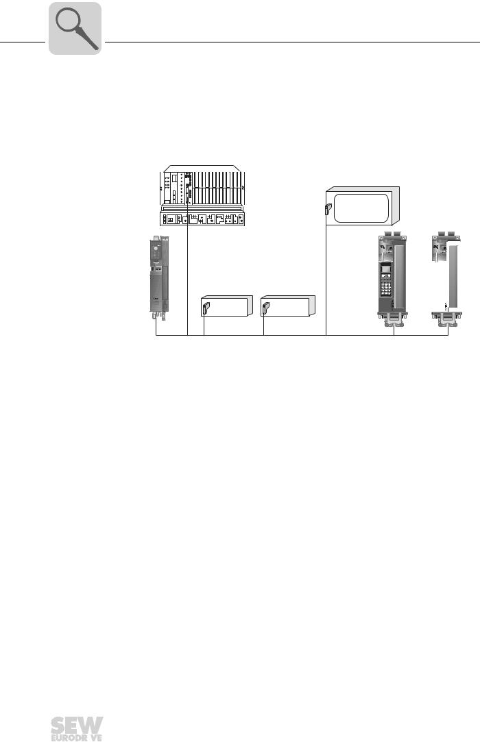
3.3.5Configuring the PROFIBUS option card
Generally, the PROFIBUS option card has been designed so that all fieldbus-specific settings, such as the station address and the default bus parameter can be made using hardware switches on the option card. This manual setting means the drive inverter can
be integrated into the PROFIBUS environment and switched on within a very short period of time.
PROFIBUS Master |
|
B |
|
® |
|
MOVITRAC |
Analog I/O |
Digital I/O |
PROFIBUS
Figure 1: PROFIBUS with MOVIDRIVE®
[1]
B |
® |
MOVIDRIVE
MOVIDRIVE® B

58687AXX
[1]Visualization
3.3.6Monitoring functions
Using a fieldbus system demands additional monitoring functions in the drive engineer-
ing, for example, time monitoring of the fieldbus (fieldbus timeout) or rapid stop concepts. For example, you can adapt MOVIDRIVE ®/MOVITRAC® monitoring functions specifically to your application. You can determine, for instance, which of the drive inverter's fault responses should be triggered in the event of a bus error. A rapid stop is
a good idea for many applications, although this can also be achieved by "freezing" the last setpoints so the drive continues operating with the most recently valid setpoints (such as with a conveyor belt). As the control terminals also function in fieldbus operation, you can still implement fieldbusndependent-i emergency stop concepts via the terminals of the drive inverter.
Phone: 800.894.0412 - Fax: 888.723.4773 - Web: www.clrwtr.com - Email: info@clrwtr.com
12 |
|
|
Manual – DFP21B PROFIBUSDP-V1 Fieldbus Interface |
|
|
|
|
|
|
|
|
|
|
|
|

Introduction |
3 |
|
Features |
||
|
3.3.7Diagnostics
The MOVIDRIVE® drive inverter and the MOVITRAC® B frequency inverter offer you numerous diagnostics options for startup and service. For example, you can use the integrated fieldbus monitor to control setpoint values sent from the higher-level control as well as the actual values.
3.3.8Fieldbus monitor
Furthermore, you are supplied with a variety of additional information about the status
of the fieldbus option card. The fieldbus monitor function in conjunction with the MOVITOOLS® MotionStudio PC software offers you an easy-to-use diagnostic tool for setting all drive parameters (including the fieldbus parameters) and for displaying the fieldbus and device status information in detail.
Phone: 800.894.0412 - Fax: 888.723.4773 - Web: www.clrwtr.com - Email: info@clrwtr.com
Manual – DFP21B PROFIBUSDP-V1 Fieldbus Interface |
|
|
13 |
|
|
|
|
|
|
|
|
|
|
|
|

4 |
Assembly and Installation Notes |
|
Installing the DFP21B option card in MOVIDRIVE® MDX61B |
||
|
4 Assembly and Installation Notes
This section contains information about as sembly and installation of the DFP21B option card in the MOVIDRIVE® MDX61B, MOVITRAC® B and UOH11B gateway housing.
4.1Installing the DFP21B option card in MOVIDRIVE® MDX61B
Only SEW-EURODRIVE engineers are allowed to install or remove option cards for MOVIDRIVE® MDX61B size 0.
•Option cards can only be installed or removed by users for MOVIDRIVE® MDX61B sizes 1 to 6.
4.1.1Before you start
The DFP21B option card must be plugged into the fieldbus slot.
Observe the following notes before installing or removing an option card:
•Disconnect the inverter from the power.Switch off the DC 24 V and the supply voltage.
•Take appropriate measures to protect the option card from electrostatic charge (use discharge strap, conductive shoes, and so on) before touching it.
•Before installing the option card, remove the keypad and the front cover.
•After installing the option card, replace the keypad and the front cover.
•Keep the option card in its original pa ckaging until immediately before you are ready to install it.
•Hold the option card by its edges only. Do not touch any components.
Phone: 800.894.0412 - Fax: 888.723.4773 - Web: www.clrwtr.com - Email: info@clrwtr.com
14 |
|
|
Manual – DFP21B PROFIBUSDP-V1 Fieldbus Interface |
|
|
|
|
|
|
|
|
|
|
|
|
Assembly and Installation Notes |
4 |
|
Installing the DFP21B option card in MOVIDRIVE® MDX61B |
||
|
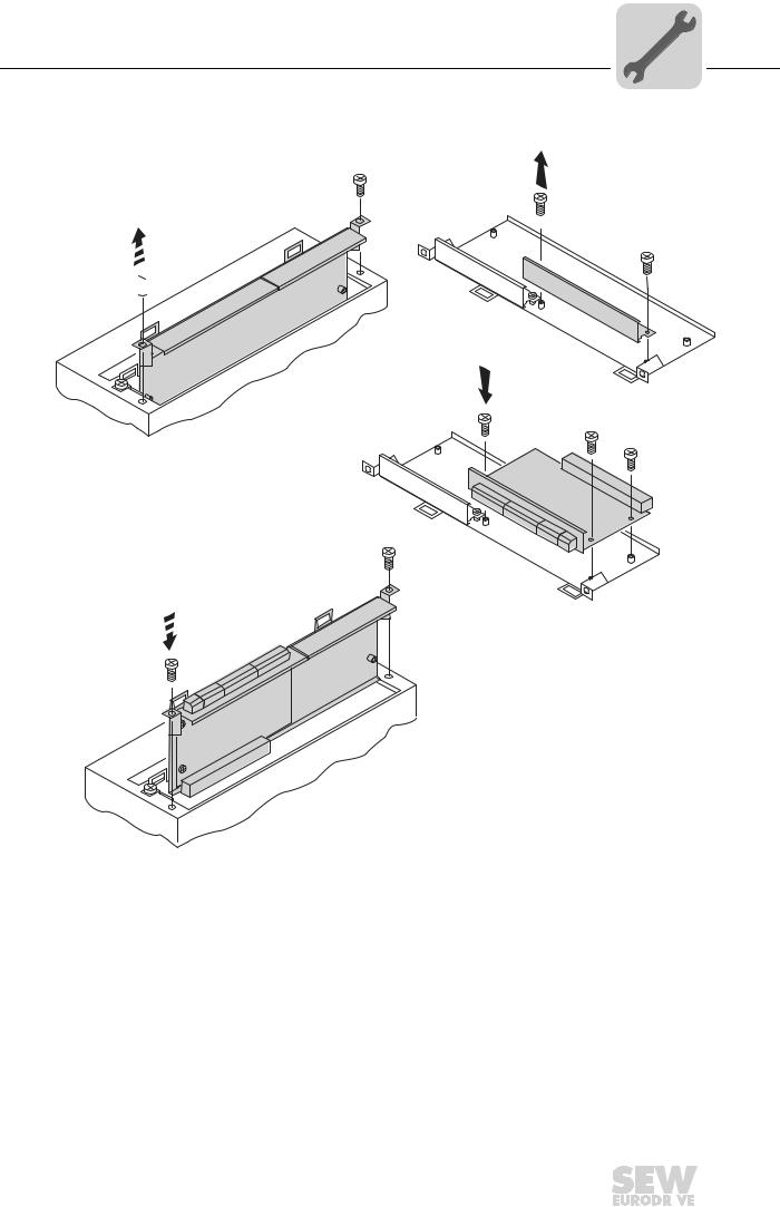
4.1.2Installing and removing an option card
2.
1.
3.
4.
53001AXX
Figure 2: Installing an option card in MOVIDRIVE® MDX61B sizes 1 to 6
1.Remove the two retaining screws holdingthe card retaining bracket. Pull the card retaining bracket out evenly from the slot (do not twist!).
2. Remove the two retaining screws of eth black cover plate on the card retaining bracket. Remove the black cover plate.
3.Position the option card onto the retaining bracket so that the three retaining screws fit into the corresponding bores on the card retaining bracket.
4.Insert the retaining bracket with installed op tion card into the slot, pressing slightly so it is seated properly. Secure the card reta ining bracket with the two retaining screws.
5.To remove the option card, follow the instructions in reverse order.
Phone: 800.894.0412 - Fax: 888.723.4773 - Web: www.clrwtr.com - Email: info@clrwtr.com
Manual – DFP21B PROFIBUSDP-V1 Fieldbus Interface |
|
|
15 |
|
|
|
|
|
|
|
|
|
|
|
|
4 |
Assembly and Installation Notes |
|
Installing the DFP21B option card in MOVITRAC® B |
||
|
4.2Installing the DFP21B option card in MOVITRAC® B
•MOVITRAC® B does not require special firmware status.
•Only SEW-EURODRIVE engineers are allowed to install or remove option cards for MOVITRAC® B.
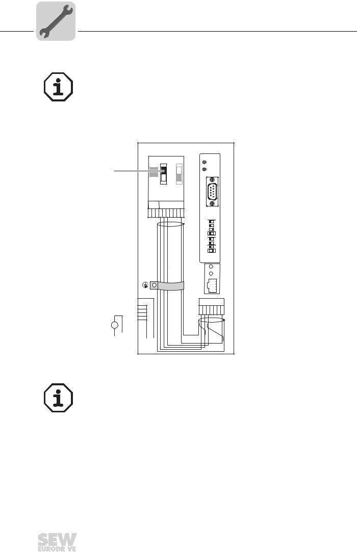
4.2.1SBus connection
|
MOVITRAC® B |
|
|
S1 |
S2 |
DFP21B |
|
RUN |
|||
|
|
||
[1] |
ON |
BUS |
|
FAULT |
|
OFF |
|
|
|
X44 |
|
|
|
|
|
|
9 |
5 |
|
|
|
|
||
FSC11B |
6 |
1 |
||
X45 |
X46 |
X30 |
||
H L 1 2 3 4 5 6 7 |
||||
|
|
|||
|
|
0 1 |
||
|
|
20 |
|
|
|
|
21 |
|
|
|
|
22 |
|
|
|
|
23 |
|
|
|
|
24 |
|
|
|
|
25 |
|
|
|
|
26 |
|
|
|
|
AS |
|
|
|
|
ADDRESS |
||
H1
H2
|
X24 |
X12 |
X26 |
1
2 1 2 3 4 5 6 7
3
+4
5
24V = |
|
|
|
|
|
6 |
|
– |
|
24V IO |
|
|
|
7 |
|
|
|
|
8 |
||||
|
|
|
|||||
|
|
|
|
|
|
|
9 |
|
|
GND |
|
|
|
||
|
|
|
|
|
|
||
59185AXX
[1]Terminating resistor activated, S1 = ON
The DFP21B features an integrated SBus terminating resistor and must therefore always be installed at the beginning of the SBus connection.
The address of the DFP21B is always 0.
X46 |
X26 |
|
|
X46:1 |
X26:1 |
|
SC11 SBus +, CAN high |
|
|
|
|
X46:2 |
X26:2 |
|
SC12 SBus , CAN low |
|
|
|
|
X46:3 |
X26:3 |
|
GND, CAN GND |
|
|
|
|
X46:7 |
X26:7 |
|
DC 24 V |
|
|
|
|
|
|
|
|
X12 |
|
|
|
X12:8 |
+24-V input |
|
|
|
|
||
X12:9 |
GND reference potential for the binary inputs |
||
|
|
|
|
|
Phone: 800.894.0412 - Fax: 888.723.4773 - Web: www.clrwtr.com - Email: info@clrwtr.com |
||
16 |
|
|
Manual – DFP21B PROFIBUSDP-V1 Fieldbus Interface |
|
|
||
|
|
|
|
|
|
|
|
|
|
|
|
Assembly and Installation Notes |
4 |
|
Installing the DFP21B option card in MOVITRAC® B |
||
|
To simplify cabling, the DFP21B can be supplied with DC 24V from X46.7 of the MOVITRAC® to X26.7.
MOVITRAC® must be supplied with DC 24V at terminals X12.8 and X12.9 when supplying the DFP21B by MOVITRAC®.
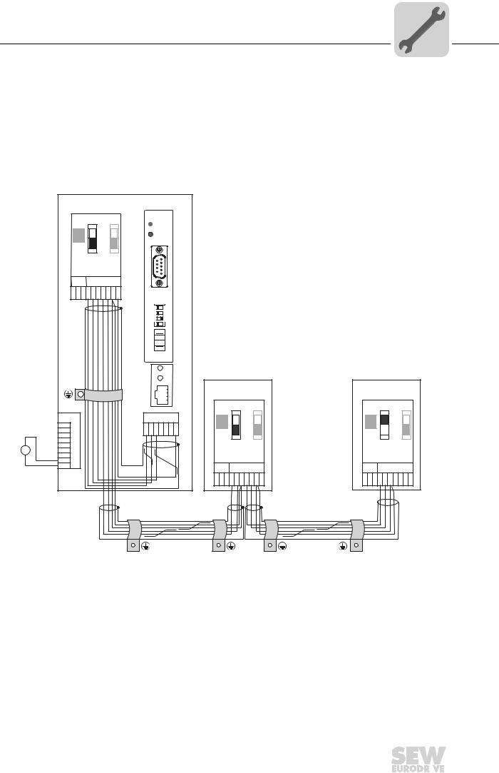
4.2.2System bus connection
MOVITRAC® B
DFP21B
S1 S2
 RUN
RUN
ON |
BUS |
|
FAULT
OFF
X44
9 |
5 |
|
FSC11B |
6 |
1 |
|
|
|
|
|
X45 |
X46 |
|
|
H L 1 2 3 4 5 6 7 |
X30 |
|
|
|
0 1 |
|
20 |
|
21 |
|
22 |
|
23 |
24  25
25  26
26 
AS 
ADDRESS
|
|
|
H1 |
|
|
|
H2 |
|
|
|
X24 |
|
|
X12 |
X26 |
|
|
1 |
|
|
|
2 |
1 2 3 4 5 6 7 |
|
|
3 |
|
+ |
4 |
|
|
5 |
|
||
24V |
= |
6 |
|
- |
24V IO |
7 |
|
|
|
8 |
|
|
GND |
9 |
|
|
|
|
|
MOVITRAC® B |
MOVITRAC® B |
||||
|
S1 |
S2 |
|
S1 |
S2 |
|
ON |
|
|
ON |
|
|
OFF |
|
|
OFF |
|
X44 |
|
|
X44 |
|
|
FSC11B |
|
FSC11B |
|
||
X45 |
X46 |
|
X45 |
X46 |
|
H L 1 2 3 4 5 6 7 |
H L 1 2 3 4 5 6 7 |
||||
59186AXX
Figure 3: System bus connection
DFP |
|
MOVITRAC® B |
|
GND |
= System bus reference |
GND |
= System bus reference |
SC11 |
= System bus high |
SC22 |
= System bus low, outgoing |
SC12 |
= System bus low |
SC21 |
= System bus high, outgoing |
|
|
SC12 |
= System bus low, incoming |
|
|
SC11 |
= System bus high, incoming |
|
|
S12 |
= System bus terminating resistor |
Phone: 800.894.0412 - Fax: 888.723.4773 - Web: www.clrwtr.com - Email: info@clrwtr.com
Manual – DFP21B PROFIBUSDP-V1 Fieldbus Interface |
|
|
17 |
|
|
|
|
|
|
|
|
|
|
|
|

4 |
Assembly and Installation Notes |
|
Installing the DFP21B option card in MOVITRAC® B |
||
|
Note:
•Use a two-core twisted and shielded copper cable (data transmission cable with
braided copper shield). Connect the shield flatly on both sides of the electronics shield clamp of MOVITRAC®. Also connect the ends of the shield to GND. The cable must meet the following specifications:
–Core cross-section 0.75 mm2 (AWG18)
–Line resistance 120 Ω at 1 MHz
–Capacitance per unit length ≤ 40 pF/m (12 pF/ft) at 1 kHz
•The permitted total cable length depends on the baud rate setting of the SBus:
– |
250 kbaud: |
160 m (528 ft) |
– |
500 kbaud: |
80 m (264 ft) |
– |
1000 kbaud: |
40 m (132 ft) |
•Connect the system bus terminating resistor (S1 = ON) at the en d of the system bus connection. Switch off the terminating resistor on the other units (S1 = OFF). The DFP21B gateway must always be connected ei ther at the beginning or the end of the system bus connection and features a permanently installed terminating resistor.
•There must not be any potential displacement between the units connected with the SBus. Take suitable measures to avoid potential displacement, such as connecting the unit ground connectors using a separate cable.
•Point-to-point wiring is not permitted.
Phone: 800.894.0412 - Fax: 888.723.4773 - Web: www.clrwtr.com - Email: info@clrwtr.com
18 |
|
|
Manual – DFP21B PROFIBUSDP-V1 Fieldbus Interface |
|
|
|
|
|
|
|
|
|
|
|
|

Assembly and Installation Notes |
4 |
|
Assembling and installing the UOH11B gateway housing |
||
|
4.3Assembling and installing the UOH11B gateway housing
SC11 Systembus +, CAN high SC12 Systembus -, CAN low GND, CAN GND
UOH11B |
|
DFP21B |
|
RUN |
|
BUS |
|
FAULT |
|
9 |
5 |
|
|
6 |
1 |
|
|
X30 |
|
0 1 |
|
20 |
|
21 |
|
22 |
|
23 |
|
24 |
|
25 |
|
26 |
|
AS |
|
ADDRESS |
|
|
H1 |
|
H2 |
X24 |
|
SEW Drive |
|
X26 |
|
1 2 3 4 5 6 7 |
|
|
+ 24 V |
|
GND |
58121BXX
X26 |
|
X26:1 |
SC11 system bus +, CAN high |
|
|
X26:2 |
SC12 system bus, CAN low |
|
|
X26:3 |
GND, CAN GND |
|
|
X26:6 |
GND, CAN GND |
|
|
X26:7 |
DC 24 V |
|
|
The gateway housing has a power supply of DC 24V that is connected to X26.
Phone: 800.894.0412 - Fax: 888.723.4773 - Web: www.clrwtr.com - Email: info@clrwtr.com
Manual – DFP21B PROFIBUSDP-V1 Fieldbus Interface |
|
|
19 |
|
|
|
|
|
|
|
|
|
|
|
|
4 |
Assembly and Installation Notes |
|
Connection and terminal description of the DFP21B option |
||
|
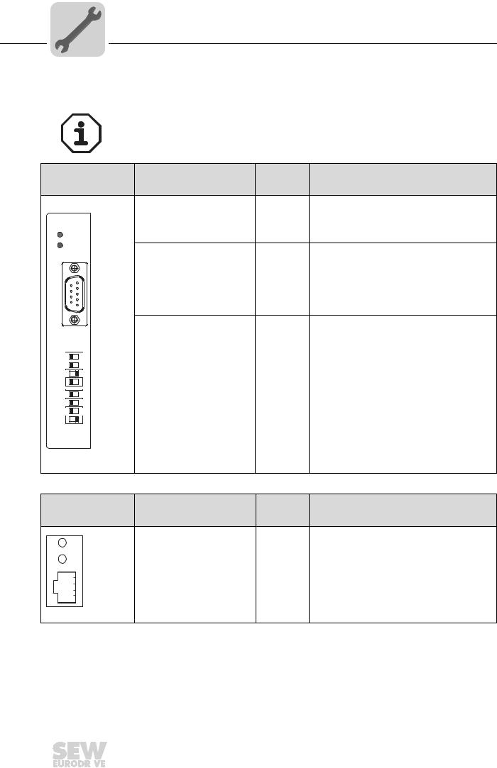
4.4Connection and terminal description of the DFP21B option
Part number |
PROFIBUS interface type DFP21B option: 824 240 2 |
|
The "PROFIBUS interface type DFP21B" option is only possible in conjunction with |
|
MOVIDRIVE® MDX61B, not with MDX60B. |
|
The DFP21B option must be plugged into the fieldbus slot. |
|
|
|
DIP |
|
Front view of DFP21B |
Description |
switches |
Function |
|
|
|
|
Terminal |
|
|
|
RUN: PROFIBUS operation |
|
Indicates that the bus electronics are operating |
|
|
LED (green) |
|
correctly. |
DFP21B |
BUS FAULT: PROFIBUS error |
|
Indicates PROFIBUSDP error. |
|
|
|
|
||
RUN |
|
LED (red) |
|
|
|
|
|
|
|
BUS |
|
ADDRESS: DIP switch for set- |
20 |
Significance: 1 |
FAULT |
||||
|
|
ting the PROFIBUS station |
21 |
Significance: 2 |
|
|
address |
22 |
Significance: 4 |
|
|
|
23 |
Significance: 8 |
9 |
5 |
|
24 |
Significance: 16 |
|
|
25 |
Significance: 32 |
|
|
|
|
||
6 |
1 |
|
26 |
Significance: 64 |
|
|
AS |
Autosetup for gateway operation |
|
|
|
|
||
|
|
X30: PROFIBUS connection |
X30:1 |
N.C. |
X30 |
|
X30:2 |
N.C. |
|
|
|
|
X30:3 |
RxD/TxD-P |
0 1 |
|
X30:4 |
CNTR-P |
|
20 |
|
|
X30:5 |
DGND (M5V) |
21 |
|
|
X30:6 |
VP (P5V/100 mA) |
22 |
|
|
X30:7 |
N.C. |
23 |
|
|
X30:8 |
RxD/TxD-N |
24 |
|
|
X30:9 |
DGND (M5V) |
|
|
|
|
|
25 |
|
|
|
|
26 |
|
|
|
|
AS |
|
|
|
|
ADDRESS |
|
|
|
|
|
59110AXX |
|
|
|
Front view of |
|
|
|
|
MOVITRAC® B, DFP21B |
Description |
|
Function |
|
and UOH11B |
|
|
|
|
|
H1 |
LED H1 (red) |
|
System error (only for gateway functions) |
|
H2 |
LED H2 (green) |
|
Reserved |
|
X24 |
X24 X terminal |
|
RS-485 interface for diagnostics via PC and |
|
|
|
|
MOVITOOLS® MotionStudio |
|
|
|
|
(only applies to MOVITRAC® B) |
|
58129axx |
|
|
|
Phone: 800.894.0412 - Fax: 888.723.4773 - Web: www.clrwtr.com - Email: info@clrwtr.com
20 |
|
|
Manual – DFP21B PROFIBUSDP-V1 Fieldbus Interface |
|
|
|
|
|
|
|
|
|
|
|
|
Assembly and Installation Notes |
4 |
|
Pin assignment |
||
|
4.5Pin assignment
Connection to the PROFIBUS network using a 9-pin sub D plug according to IEC 61158. The T-bus connection must be made using a connector with the corresponding configuration.
[2]
|
1 |
RxD/TxD-P |
3 |
|
6 |
RxD/TxD-N |
8 |
|
|
|
CNTR-P |
4 |
|
|
|
|
[3] |
||
|
|
DGND (M5V) |
5 |
|
9 |
|
|
||
5 |
VP (P5V/100mA) |
6 |
|
|
|
DGND (M5V) |
9 |
|
|
|
|
|
[1]
06227AXX
Figure 4: Assignment of 9-pin sub D plug to IEC 61158
[1]9-pin sub-D connector
[2]Signal line, twisted
[3]Conductive, wide area connection is necessary between the connector housing and the shield
4.5.1MOVIDRIVE® / MOVITRAC® B / PROFIBUS connection
As a rule, the DFP21B option is connected to the PROFIBUS system using a shielded twisted-pair cable. Observe the maximum supported transmission rate when selecting the bus connector.
The twisted-pair cable is connected to the PROFIBUS connector at pin 3 (RxD/TxD-P) and pin 8 (RxD/TxD-N). Communication takes place via these two contacts. The RS-485 signals RxD/TxD-P and RxD/TxD-N must beconnected to the same contacts in all PROFIBUS stations. Otherwise, no communication is possible via the bus medium.
The PROFIBUS interface sends a TTL control signal for a repeater or fiber optic adapter (reference = pin 9) via pin 4 (CNTR-P).
4.5.2Baud rates greater than 1.5 MBaud
The DFP21B option with baud rates > 1.5 MBaud can only be operated with special 12-
MBaud PROFIBUS connectors.
Phone: 800.894.0412 - Fax: 888.723.4773 - Web: www.clrwtr.com - Email: info@clrwtr.com
Manual – DFP21B PROFIBUSDP-V1 Fieldbus Interface |
|
|
21 |
|
|
|
|
|
|
|
|
|
|
|
|

4 |
Assembly and Installation Notes |
|
Shielding and routing bus cables |
||
|
4.6Shielding and routing bus cables
The PROFIBUS interface supports RS-485transmission technology and requires the cable type A to IEC 61158 as the physical medium for the PROFIBUS. This cable must be a shielded, twisted-pair cable.
Correct shielding of the bus cable attenuateselectrical interference that may occur in industrial environments. The following measures ensure the best possible shielding:
•Manually tighten the mounting screws on the connectors, modules, and equipotential bonding conductors.
•Use only connectors with a metal housing or a metallized housing.
•Connect the shielding in the connector over a wide surface area.
•Apply the shielding of the bus line on both ends.
•Route signal and bus cables in separate cable ducts. Do not route them parallel to power cables (motor leads).
•In industrial environments, use metallic, grounded cable racks.
•Route the signal cable and the corresponding equipotential bonding close to each other using the shortest possible route.
•Avoid using plug connectors to extend bus cables.
•Route the bus cables closely along existing grounding surfaces.
In case of fluctuations in the ground potential, a compensating current may flow via the bilaterally connected shield that is also connected to the protective earth (PE). In this case, make adequate provision for equipotential bonding in accordance with the relevant VDE regulations.
4.7Bus termination
The DFP21B option is not provided with bus terminating resistors. This enables the bus system to be put into operation more easily and reduces the number of error sources.
Use a plug with an integrated bus terminatingresistor if the DFP21B option is at the beginning or end of a PROFIBUS segment and only one PROFIBUS cable is leading to the DFP21B.
Switch on the bus terminating resistors for this PROFIBUS connector.
Phone: 800.894.0412 - Fax: 888.723.4773 - Web: www.clrwtr.com - Email: info@clrwtr.com
22 |
|
|
Manual – DFP21B PROFIBUSDP-V1 Fieldbus Interface |
|
|
|
|
|
|
|
|
|
|
|
|
Assembly and Installation Notes |
4 |
|
Setting the station address |
||
|
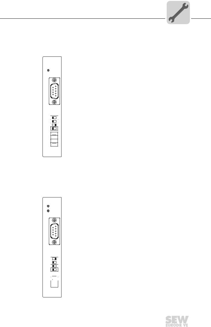
4.8Setting the station address
The PROFIBUS station address is set using DIP switches 20 to 26 on the option card. MOVIDRIVE® supports the address range 1 to 125.
DFP21B
 RUN
RUN
BUS
FAULT
9 5
6 1
The default setting for the PROFIBUS station address is 4:
20 → Significance: 1 × 0 = 0
21 → Significance: 2 × 0 = 0
22 → Significance: 4 × 1 = 4
23 → Significance: 8 × 0 = 0
24 → Significance: 16 × 0 = 0
25 → Significance: 32 × 0 = 0
26 → Significance: 64 × 0 = 0
X30 |
|
0 |
1 |
20 |
|
21 |
|
22 |
|
23 |
|
24  25
25  26
26  AS
AS
ADDRESS
59110AXX
Any change made to the PROFIBUS station address during ongoing operation does not take effect immediately. The change only come s into effect when the inverter is switched on again (power supply + 24 V OFF/ON). Theinverter displays the current station address in fieldbus monitor parameter P092 "Fieldbus address" (display with DBG60B or MOVITOOLS®/SHELL).
Example: Setting the PROFIBUS station address 17
DFP21B |
20 |
→ |
Significance: 1 × |
|
1 = 1 |
|
|
RUN |
|
21→ |
Significance: 2 × |
0 = 0 |
|
||
BUS |
|
22 |
→ |
Significance: 4 × |
|
0 = 0 |
|
FAULT |
23 |
→ |
Significance: 8 × |
|
0 = 0 |
|
|
|
|
24 |
→ |
Significance: 16 |
× |
1 = |
16 |
|
|
25 |
→ |
Significance: 32 |
× |
0 = |
0 |
9 |
5 |
26 |
→ |
Significance: 64 |
× |
0 = |
0 |
|
|
|
|
|
|
|
|
61
X30 |
|
0 |
1 |
20 |
|
21 |
|
22 |
|
23 |
|
24  25
25  26
26 
AS
ADDRESS
59111AXX
Phone: 800.894.0412 - Fax: 888.723.4773 - Web: www.clrwtr.com - Email: info@clrwtr.com
Manual – DFP21B PROFIBUSDP-V1 Fieldbus Interface |
|
|
23 |
|
|
|
|
|
|
|
|
|
|
|
|

4 |
Assembly and Installation Notes |
|
Operating mode displays: option DFP21B |
||
|
4.9Operating mode displays: option DFP21B
4.9.1PROFIBUS LEDs
The PROFIBUS interface DFP21B option card has 2 LEDs that indicate the current status of the DFP21B option and the PROFIBUS system.
DFP21B
RUN
BUS
FAULT
58361AXX
RUN LED (green) |
• The RUN LED (green) indicates that the bus electronics are operating correctly |
|||
|
|
|
|
|
|
RUN |
Cause of error |
Remedy |
|
|
Green |
• PROFIBUS hardware OK. |
– |
|
|
|
|
|
|
|
Orange |
• The card is booting. |
– |
|
|
|
|
|
|
|
Off |
• Hardware defect in the bus electronics. |
• Switch the unit on again. Consult SEW |
|
|
|
|
|
service if the error occurs again. |
|
|
|
|
|
|
Flashes |
• PROFIBUS address is set higher than 125 |
• |
Use parameter P093 Fieldbus Address to |
|
2Hz |
or to 0. |
|
check the address set with the DIP |
|
|
|
|
switches. |
|
|
|
• |
Reset the inverter. |
|
|
|
|
|
|
Flashes |
• No error, only display. |
• The inverter is restarting. |
|
|
1Hz |
|
|
|
|
|
|
|
|
LED BUS FAULT |
• The BUS FAULT LED (red) indicates a PROFIBUSDP fault. |
|||
(red) |
|
|
|
|
BUS FAULT |
Cause of error |
Remedy |
||
|
||||
|
Red |
• Connection to the DP master has |
• Check the PROFIBUSDP connection on |
|
|
|
dropped. |
the unit. |
|
|
|
• Unit does not detect a PROFIBUS baud |
• Check the project planning of the DP |
|
|
|
rate. |
master. |
|
|
|
• Possible bus interruption. |
• Check all cables in your PROFIBUS DP |
|
|
|
• DP master not in operation. |
network. |
|
|
|
|
|
|
|
Off |
• Unit is currently exchanging data with |
– |
|
|
|
the DP master (data exchange). |
|
|
|
|
|
|
|
|
Flashing |
• Unit has detected the baud rate, but is |
• Check the PROFIBUS address setting |
|
|
|
not being addressed by the DP master. |
on the DFP21B and in the project |
|
|
|
• Unit was not configured in the DP |
planning software of the DP master. |
|
|
|
master or was configured incorrectly. |
• Check the project planning of the DP |
|
|
|
|
master. |
|
|
|
|
• Use the GSD file SEWA6003.GSD with |
|
|
|
|
the identifier MOVIDRIVE®-DFP21B or |
|
|
|
|
SEW_6009.GSD for gateway operation |
|
|
|
|
with MOVITRAC® B for project planning. |
|
Phone: 800.894.0412 - Fax: 888.723.4773 - Web: www.clrwtr.com - Email: info@clrwtr.com
24 |
|
|
Manual – DFP21B PROFIBUSDP-V1 Fieldbus Interface |
|
|
|
|
|
|
|
|
|
|
|
|

Assembly and Installation Notes |
4 |
|
Operating mode displays: option DFP21B |
||
|
LEDs for gateway communication status
H1
H2
X24
|
|
58129axx |
|
|
|
LED H1 Sys-fault (red) |
Only for gateway function |
|
Status |
Status |
Description |
Red |
System error |
Gateway is not configured or one of the |
|
|
drives is inactive. |
|
|
|
Off |
SBus ok |
Gateway is configured correctly |
|
|
|
Flashing |
Bus scan |
Bus is being checked by the gateway |
|
|
|
LED H2 (green) is currently reserved.
X-terminal X24 is the RS-485 interfac for diagnostics via PC and MOVITOOLS® MotionStudio.
Phone: 800.894.0412 - Fax: 888.723.4773 - Web: www.clrwtr.com - Email: info@clrwtr.com
Manual – DFP21B PROFIBUSDP-V1 Fieldbus Interface |
|
|
25 |
|
|
|
|
|
|
|
|
|
|
|
|

I
5 |
|
Project Planning and Startup |
|
0 |
Validity of the GSD files for DFP21B |
||
|
5 Project Planning and Startup
This section provides you with information on project planning for the DP master and startup of the drive inverter for fieldbus operation.
Current versions of the GSD files for theDFP21B option are available on the SEW homepage under the heading "Software". Both GSD files can be used at the same time in one STEP7 project. Once you have downloaded and unpacked the software, you will have two directories for the operating modes PROFI-BUS DP and PROFIBUS DP-V1.
5.1Validity of the GSD files for DFP21B
PROFIBUS option |
SEW_6003.GSD for DP |
SEWA6003.GSD for DP-V1 |
SEW_6009.GSD for DP-V1 |
DFP21B074 firmware option 1: |
|
|
Gateway operation |
824 399 9.10 and higher |
ok |
ok |
No |
1820 536 4.10 and higher |
ok |
ok |
ok |
|
|
|
|
Entries in the GSD file must not be changed or expanded. SEW assumes no liability for inverter malfunctions caused by a modified GSD file.
5.2DP master project planning the with MOVIDRIVE® GSD file
A GSD file is provided for project planning for the DP master. This file must be copied into a special folder of your project planning software.
Refer to the manuals of the appropriate project planning software for details on the procedure.
5.2.1GSD file for PROFIBUSDP
Use the GSD file SEW_6003.GSD from the "DP" directory if you want to use PROFIBUS DP communication to control the drive inverter. This GSD file corresponds to the GSD revision1 and must be copied to a specialdirectory of your project planning software. Refer to the manuals ofthe appropriate project planning software for details on the procedure.
The unit master data files standardized by the PROFIBUS user group can be read by all PROFIBUS DP masters.
Project planning tool |
DP master |
File name |
All DP project planning tools to EN 50170 (V2) |
For DP master |
SEW_6003.GSD |
|
standard |
|
|
|
|
Siemens S7 hardware configuration |
For all S7 DP masters |
|
|
|
|
Siemens S5 COM PROFIBUS |
For IM 308C etc. |
|
|
|
|
Phone: 800.894.0412 - Fax: 888.723.4773 - Web: www.clrwtr.com - Email: info@clrwtr.com
26 |
|
|
Manual – DFP21B PROFIBUSDP-V1 Fieldbus Interface |
|
|
|
|
|
|
|
|
|
|
|
|

Project Planning and Startup |
I |
5 |
DP master project planning the with MOVIDRIVE® GSD file |
|
|
0 |
|
|
|
|
5.2.2GSD file for PROFIBUS DP-V1
Use the GSD file SEWA6003.GSD from the "DP-V1" directory if you want to use the parameter setting options of DP-V1 additionin to the standard PROFIBUS DP communication to control the drive inverter.
This GSD file corresponds to GSD revision3. If you use older, non-DP-V1-capable PROFIBUS options, a connection is notestablished between the DP-V1 master and DFP21B. In this case, the BUS FAULT LED of DFP21B remains switched on after the DP-V1 master has started. The DP V1 master will indicate that the connection cannot be established.
So that the GSD files are easy to identify, they are assigned the name for PROFIBUS- DP-V1 and displayed in a special subdirectoryin the project planning software for the DP-V1 master (see following screenshot).
53545AXX
Phone: 800.894.0412 - Fax: 888.723.4773 - Web: www.clrwtr.com - Email: info@clrwtr.com
Manual – DFP21B PROFIBUSDP-V1 Fieldbus Interface |
|
|
27 |
|
|
|
|
|
|
|
|
|
|
|
|

5 |
I |
Project Planning and Startup |
|
DP master project planning the with MOVIDRIVE® GSD file |
|
|
0 |
|
|
|
5.2.3Project planning procedure
Proceed as follows for project planning for MOVIDRIVE ® with PROFIBUS DP interface:
1.Read the README_GSDA6003.PDF file, which you receive with the GSD file for further current information on project planning.
2.Install (copy) the GSD file according to th e requirements of your project planning soft-
ware. Once the file has been installed corre ctly, the device appears next to the slave stations with the designation MOVIDRIVE®+DFP21.
3.Add the interface module under the name MOVIDRIVE®+DFP21 to the PROFIBUS structure and assign the station address.
4.Select the process data configuration requ ired for your application (see section 5.2.4 on page 29).
5.Enter the I/O or peripheral addresses for the configured data widths.
After project planning, you can start PROFIBUS DP. The red BUS FAULT LED indicates the status of the project planning (OFF = project planning OK).
Phone: 800.894.0412 - Fax: 888.723.4773 - Web: www.clrwtr.com - Email: info@clrwtr.com
28 |
|
|
Manual – DFP21B PROFIBUSDP-V1 Fieldbus Interface |
|
|
|
|
|
|
|
|
|
|
|
|

Project Planning and Startup |
I |
5 |
DP master project planning the with MOVIDRIVE® GSD file |
|
|
0 |
|
|
|
|
5.2.4DP configuration for MOVIDRIVE® MDX61B (SEWA6003.GSD)
The drive inverter must be given a specific DP configuration by the DP master to define the type and number of input and output data used for transmission. You can
•Control the drive using process data
•Read and write all drive parameters using the parameter channel
•Use a data exchange medium of your choice between IPOSplus and the controller
MOVIDRIVE® drive inverters make it possible tohave different DP configurations for exchanging data between the DP master and the inverter. The following table provides additional information about all possible DP configurations for the MOVIDRIVE® range. The "Process data configuration" column lists the names of the configurations. This text is also displayed as selection list within th e project planning software for the DP master. The "DP configurations" column shows which configuration data is sent to the inverter when the PROFIBUS DP connection is being established.
Process data |
Meaning / notes |
DP configuration |
|
configuration |
|
|
|
|
|
0 |
1 |
1 PD |
MOVIDRIVE® control via 1 process data word |
F0hex |
- |
2 PD |
MOVIDRIVE® control via 2 process data words |
F1 |
- |
|
|
hex |
|
3 PD |
MOVIDRIVE® control via 3 process data words |
F2 |
- |
|
|
hex |
|
6 PD |
MOVIDRIVE® control via 6 process data words |
0hex |
F5hex |
|
(PD4-PD6 can only be used with IPOSplus® ) |
|
|
10 PD |
MOVIDRIVE® control via 10 process data words |
0hex |
F9hex |
|
(PD4-PD10 can only be used with IPOSplus® ) |
|
|
Param + 1 PD |
MOVIDRIVE® control via 1 process data word |
F3hex |
F0hex |
|
Parameter setting via 8 byte parameter channel |
|
|
Param + 2 PD |
MOVIDRIVE® control via 2 process data words |
F3hex |
F1hex |
|
Parameter setting via 8 byte parameter channel |
|
|
Param + 3 PD |
MOVIDRIVE® control via 3 process data words |
F3hex |
F2hex |
|
Parameter setting via 8 byte parameter channel |
|
|
Param + 6 PD |
MOVIDRIVE® control via 6 process data words |
F3hex |
F5hex |
|
Parameter setting via 8 byte parameter channel |
|
|
|
(PD4-PD10 can only be used with IPOSplus® ) |
|
|
Param + 10 PD |
MOVIDRIVE® control via 10 process data words |
F3hex |
F9hex |
|
Parameter setting via 8 byte parameter channel |
|
|
|
(PD4-PD10 can only be used with IPOSplus® ) |
|
|
Phone: 800.894.0412 - Fax: 888.723.4773 - Web: www.clrwtr.com - Email: info@clrwtr.com
Manual – DFP21B PROFIBUSDP-V1 Fieldbus Interface |
|
|
29 |
|
|
|
|
|
|
|
|
|
|
|
|

5 |
I |
Project Planning and Startup |
|
DP master project planning the with MOVIDRIVE® GSD file |
|
|
0 |
|
|
|
|
|
Universal DP |
If you select the "Universal Module" DP co nfiguration (S7 HWConfig), you can structure |
|
configuration |
the DP configuration individually, houghalt you must comply with the following |
|
|
conditions. |
Module 0 (DP identifier 0) defines the parameter channel of the inverter.
To ensure the parameter settings are made correctly, you must always transfer the parameter channel consistently for the entire length.
Length |
Function |
0 |
Parameter channel deactivated |
|
|
8 I/O bytes or 4 I/O words |
Parameter channel is used |
|
|
Module 1 (DP identifier 1) defines the process data channel of the inverter.
In addition to the process data configuratio predefined in the GSD file, you can also specify the process data configuration with 4, 5, 7, 8 and 9 process data words. Ensure that the number of input and output words is always the same. If the lengths are different, data cannot be exchanged. In this case, theBUS FAULT LED flashes and the parameter P090 PD Configuration indicates the configuration error with 0PD.
Length |
Function |
||
2 |
I/O bytes or 1 I/O word |
1 process data word |
|
|
|
|
|
4 |
I/O bytes or 2 I/O words |
2 process data words |
|
|
|
|
|
6 |
I/O bytes or 3 I/O words |
3 process data words |
|
|
|
|
|
8 |
I/O bytes or 4 I/O words |
4 process data words |
|
|
|
|
|
10 |
I/O bytes or 5 I/O words |
5 process data words |
|
|
|
|
|
12 |
I/O bytes or 6 I/O words |
6 process data words |
|
|
|
|
|
14 |
I/O bytes or 7 I/O words |
7 process data words |
|
|
|
|
|
16 |
I/O bytes or 8 I/O words |
8 process data words |
|
|
|
|
|
18 |
I/O bytes or 9 I/O words |
9 process data words |
|
|
|
|
|
20 |
I/O bytes or 10 I/O words |
10 process data words |
|
|
|
|
|
Phone: 800.894.0412 - Fax: 888.723.4773 - Web: www.clrwtr.com - Email: info@clrwtr.com
30 |
|
|
Manual – DFP21B PROFIBUSDP-V1 Fieldbus Interface |
|
|
|
|
|
|
|
|
|
|
|
|
 Loading...