


T
MOVIMOT®
Operating Instructions
Category 3D
(Dust Explosion Protection)
Edition 03/2000
09/011/98
<![if ! IE]><![endif]>0918 581X / 0300

Contents
 I 0
I 0
kVA n f
i
P Hz
1 |
Important Notes................................................................................................. |
4 |
|
2 |
Safety Notes ...................................................................................................... |
5 |
|
|
2.1 |
Information for using MOVIMOT®in category 3D..................................... |
6 |
3 |
Structure of the Unit ......................................................................................... |
7 |
|
|
3.1 |
Type designation, nameplates .................................................................. |
7 |
|
3.2 |
Structure of the inverter unit...................................................................... |
8 |
|
3.3 |
Description of the controls ........................................................................ |
9 |
4 |
Mechanical Installation................................................................................... |
10 |
|
5 |
Electrical Installation ...................................................................................... |
11 |
|
|
5.1 |
Installation guidelines.............................................................................. |
11 |
|
5.2 |
Protection concept .................................................................................. |
13 |
|
5.3 |
Operating modes .................................................................................... |
13 |
|
5.4 |
Connection with binary control................................................................ |
14 |
|
5.5 |
Connection with MLA12A option............................................................. |
15 |
|
5.6 |
Connection with RS-485 bus mode ........................................................ |
16 |
6 |
Startup.............................................................................................................. |
17 |
|
|
6.1 |
Important startup instructions.................................................................. |
17 |
|
6.2 |
Startup with binary control ...................................................................... |
18 |
|
6.3 |
Startup with the MLA12A option ............................................................. |
20 |
|
6.4 |
Startup with RS-485 bus operation ......................................................... |
22 |
|
6.5 |
Serial communication.............................................................................. |
24 |
7 |
Operation and Service .................................................................................... |
26 |
|
|
7.1 |
Status LED.............................................................................................. |
26 |
|
7.2 |
Status LED messages ............................................................................ |
26 |
|
7.3 |
List of errors ............................................................................................ |
27 |
8 |
Inspection and Maintenance .......................................................................... |
28 |
|
|
8.1 |
Inspection and maintenance periods ..................................................... |
28 |
|
8.2 |
Inspection and maintenance work on the motor .................................... |
29 |
|
8.3 |
Inspection and maintenance of the brake ............................................... |
31 |
9 |
Technical data (relating to 4 kHz PWM frequency) ...................................... |
36 |
|
|
9.1 |
MOVIMOT®in category 3D .................................................................... |
36 |
|
9.2 |
Technical data MLA12A option ............................................................... |
37 |
|
9.3 |
Regenerative load capacity of brake coil ................................................ |
37 |
|
9.4 |
Work done until adjustment, working air gap, braking torque of brake ... |
37 |
|
9.5 |
Approved ball bearing types ................................................................... |
38 |
|
9.6 |
Operating characteristics ........................................................................ |
38 |
|
9.7 |
Declaration by the manufacturer............................................................. |
39 |
Operating Instructions MOVIMOT®MM..B for Use According to Category 3D |
|
|
3 |
|
|
|
|
|
|
|
|

1 |
Important Notes |
1 Important Notes
Always following the safety and warning instructions contained in this publication!
Electrical hazard
Possible consequences: Severe or fatal injuries.
Hazard
Possible consequences: Severe or fatal injuries.
Hazardous situation
Possible consequences: Slight or minor injuries.
Harmful situation
Possible consequences: Damage to the unit and the environment.
Tips and useful information
Important information about explosion protection
A requirement of fault-free operation and fulfillment of any rights to claim under guarantee is that the information in the operating instructions is adhered to. Consequently, read the operating instructions before you start working with the unit!
The operating instructions contain important information about servicing; as a result, they should be kept in the vicinity of the unit.
Waste disposal This product consists of
•Iron
• |
Aluminum |
• |
Copper |
• |
Plastic |
• |
Electronics components |
Please dispose of the parts in accordance with the applicable regulations.
4 |
|
|
Operating Instructions MOVIMOT®MM..B for Use According to Category 3D |
|
|
|
|
|
|
|
|

Safety Notes |
2 |
2Safety Notes
•Never install damaged products or take them into operation. Please submit a complaint to the transport company immediately in the event of damage.
•Only electrical specialists with the relevant accident prevention training are allowed to perform installation, startup and service work on the unit. They must also comply with the regulations in force (e.g. EN 60204, VBG 4, DIN-VDE 0100/ 0113/0160).
•Make sure that preventive measures and protection devices correspond to the applicable regulations (e.g. EN 60204 or EN 50178).
Necessary protective measures: Grounding the unit
•Disconnect the unit from the supply system prior to removing the connection box cover. Dangerous voltages may still be present for up to 1 minute after mains disconnection.
•Keep the connection box cover closed during operation.
•Just because the status LED and other display elements have gone out does not mean that the unit has been disconnected from the power supply and is deenergized.
•Mechanical blockage or unit internal safety functions of MOVIMOT® can lead to
a motor standstill. The removal of the source of the interruption or a reset of MOVIMOT®can result in an automatic restart of the motor. If, for safety reasons, this is not permissible for the driven machine, the MOVIMOT® must be disconnected from the supply system before correcting the fault.
•Important: MOVIMOT®is not suitable for hoist applications!
•Important – Danger of burns: The surface temperature of MOVIMOT® units (in particular that of the heat sink) may exceed 60° C during operation!
Operating Instructions MOVIMOT®MM..B for Use According to Category 3D |
|
|
5 |
|
|
|
|
|
|
|
|

2 |
Safety Notes |
2.1Information for using MOVIMOT® in category 3D
Standards |
MOVIMOT® units in category 3D comply with EN 50014 ("Electrical apparatus for po- |
|
|
tentially explosive atmospheres; general requirements", 2nd edition) and EN 50281-1- |
|
|
1:1998 ("Electrical apparatus for use in atmospheres containing flammable dust"), and |
|
|
therefore conform to Directive 94/9/EC (ATEX 100a). |
|
Enclosure of the |
MOVIMOT® units in category 3D are supplied with enclosure IP54 at least. The enclo- |
|
housing |
sure has to be maintained over the complete operating time as a precondition for satis- |
|
|
fying the requirements for devices in category 3D. For this reason, particular care must |
|
|
be taken even when connecting the units. |
|
|
The unit must not be operated in zone 22 atmospheres if the enclosure type is not as- |
|
|
sured! |
|
Applications |
• |
Unit group II |
|
• |
Category 3D |
• For use in zone 22
• Surface temperature 140 °C
• Ambient temperature -20 to +40 °C
6 |
|
|
Operating Instructions MOVIMOT®MM..B for Use According to Category 3D |
|
|
|
|
|
|
|
|
Type designation, nameplates |
3 |
3 Structure of the Unit
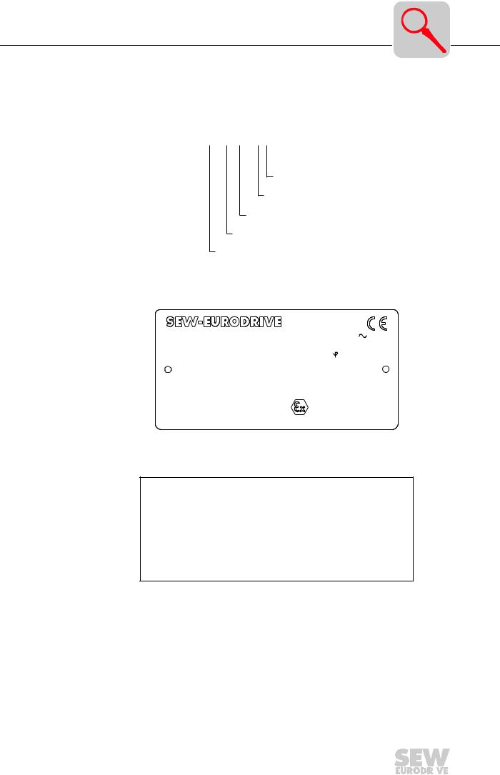
3.1Type designation, nameplates
Type designation
example MOVIMOT® MM 22 B - 503 - 04
 Version (04 = 3D category)
Connection type
Supply voltage
Version B
Motor rating
®
MOVIMOT Series
02883AEN
MOVIMOT® nameplate (example)
|
|
|
|
|
Bruchsal/Germany |
|
|||
Typ |
KA67DT100L4BMGMM30B/MLA |
|
|
|
3 |
IEC 34 |
|||
Nr. |
010012345.6.00.00 |
|
|
IM |
B3 |
|
|
||
kW |
2,2 / 50Hz |
|
|
cos |
0,99 |
|
|||
50Hz V |
400-460 |
|
|
A |
5,0 |
|
|
||
60Hz V |
400-460 |
|
|
A |
5,0 |
|
|
||
r/min |
92/1400 |
|
|
IP |
54 |
Kl. |
F |
||
Bremse |
V |
110 |
Nm 40 |
Gleichrichter |
|
||||
Kg |
54 |
|
Ma 310 |
Nm |
|
II 3 D |
T 140°C |
||
i |
15,19 |
:1 |
|
|
|
|
|
|
|
Schmierstoff |
|
|
Made in Germany |
186 853 5.10 |
|||||
03090AXX
Electronics nameplate (example)
02581AXX
Operating Instructions MOVIMOT®MM..B for Use According to Category 3D |
|
|
7 |
|
|
|
|
|
|
|
|

3 |
Structure of the inverter unit |
3.2Structure of the inverter unit
18 |
1 |
2 |
3 |
4 |
|
|
|
|
|
|
|
|
|
|
|
|
|
|
|
|
|
|
|
|
|
|
|
|
|
|
|
|
|
|
|
|
|
|
|
|
|
|
|
|
|
|
|
|
|
|
|
|
|
|
|
|
|
|
|
|
|
|
|
|
|
|
|
|
|
|
|
|
|
|
|
|
|
|
|
|
|
|
|
|
|
|
|
|
|
|
|
|
|
|
|
|
|
|
|
|
|
|
|
|
|
|
|
|
|
|
|
|
|
|
|
|
|
|
|
|
|
|
|
|
|
|
|
|
|
|
|
|
|
|
|
|
|
|
|
|
|
|
|
|
|
|
|
|
|
|
|
|
|
|
|
|
|
|
|
|
|
|
|
|
|
|
|
|
|
|
|
|
|
|
|
|
|
|
|
|
|
|
|
|
|
|
|
|
|
|
|
|
|
|
|
|
|
|
|
|
|
|
|
|
|
|
|
|
|
|
|
|
|
|
|
|
|
|
|
|
|
|
|
|
|
|
|
|
|
|
|
|
|
|
|
|
|
|
|
|
|
|
|
|
|
|
|
|
|
|
|
|
|
|
|
|
|
|
|
|
|
|
|
|
|
|
|
|
|
|
|
|
|
|
|
|
|
|
|
|
|
|
|
|
|
|
|
|
|
|
|
|
|
|
|
|
|
|
|
|
|
|
|
|
|
|
|
|
|
|
|
|
|
|
|
|
|
|
|
|
|
|
|
|
|
|
|
|
|
|
|
|
|
|
|
|
|
|
|
|
|
|
|
|
|
|
|
|
|
|
|
|
|
|
|
|
|
|
|
|
|
|
|
|
|
|
|
|
|
|
|
|
|
|
|
|
|
|
|
|
|
|
|
|
|
|
|
|
|
|
|
|
|
|
|
|
|
|
|
|
|
|
|
|
|
|
|
|
|
|
5 |
6 |
7 |
8 |
9 |
10 |
11 |
12 |
13 |
14 |
15 |
16 |
17 |
||||||||||||||||
|
|
|
|
|
|
|
|
|
|
|
|
|
|
|
|
|
|
|
|
|
|
|
|
|
|
|
|
|
|
|
|
|
|
|
|
|
|
|
|
|
|
|
|
|
|
|
|
|
|
|
|
|
|
|
|
|
|
02882AXX
Bild 1: Structure of the unit
1Identification of the circuit type
2Connection box
3Connection plug, connection unit with inverter
4Connection box cover with inverter and heat sink
5Connection unit with terminals
6Electronics terminal strip X2
7Connection of brake coil (X3)
For motors without a brake: Connection of internal braking resistor BW1/BW2 (standard)
8Power system connection L1, L2, L3 (X3) (suitable for 2 x 4 mm2)
9Screws for PE connection y
10 Cable screw fittings |
MM03B-MM15B: (2 x PG11 and 2 x PG16 |
/ from start of 2000, |
2 x M16 and 4 x M25) |
(not all visible in picture) MM22B-MM30B: (4 x PG11 and 4 x PG16 |
/ from start of 2000, |
4 x M16 and 4 x M25) |
|
11Electronics nameplate
12Safety hood for inverter electronics
13Setpoint potentiometer f1 (not visible),
accessible from the top of the connection box cover by means of a PG screw fitting
14Setpoint switch f2 (green)
15Switch t1 for ramp generator (white)
16DIP switch S1 for setting the bus address, motor protection, DC braking, PWM frequency
17Status LED (visible from the top of the connection box cover, see “Status LED” on page 26)
18Terminals for TH connection (arrangement of terminals varies according to the size of the MOVIMOT®unit)
8 |
|
|
Operating Instructions MOVIMOT®MM..B for Use According to Category 3D |
|
|
|
|
|
|
|
|

Description of the controls |
3 |
3.3Description of the controls
DIP SWITCH S1
S1/.. |
1 |
2 |
3 |
4 |
5 |
6 |
|
7 |
8 |
|
ON |
20 |
21 |
22 |
23 |
Motor protection |
DC braking |
PWM frequency |
|
||
deactivated |
16 kHz |
1) |
variable |
No func- |
||||||
|
|
|
|
|
|
|
||||
OFF |
RS-485 address |
Motor protection |
4Q operation * |
PWM frequency |
tion |
|||||
active * |
4 kHz fix * |
|
||||||||
|
|
|
|
|
|
|
||||
|
|
|
|
|
|
|
|
|
|
|
1)16 kHz PWM frequency (low-noise)
When DIP SWITCH S1/7 = ON, the units operate with a 16 kHz PWM frequency (low noise) and switch back in steps to lower pulse frequencies depending on the heat sink temperature.
*Factory setting
Setpoint potentiometer f1
Setpoint switch f2
3
4 5
6
7 8
The function of the potentiometer changes depending on the unit’s operating mode.
•Control via terminals: Setpoint f1 (selected by tl. f1/f2 = “0”)
• Control via RS-485: |
Maximum frequency fmax |
|
|
100 |
|
|
f [Hz] |
|
|
75 |
f1 |
5 |
6 |
|
|
50 |
|
|
25 |
|
|
2 |
2 3 4 5 6 7 8 9 10 Pot. position |
|
0 1 |
|
02704AEN
The function of the switch changes depending on the unit’s operating mode.
•Control via terminals: Setpoint f2 (selected by tl. f1/f2 = “1”)
• Control via RS-485: |
|
Minimum frequency fmin |
|
|
|
|
|
|||||
Setpoint switch f2 |
|
|
|
|
|
|
|
|
|
|
|
|
Detent position |
|
0 * |
1 |
2 |
3 |
4 |
5 |
6 |
7 |
8 |
9 |
10 |
|
|
|
|
|
|
|
|
|
|
|
|
|
Setpoint f2 [Hz] |
|
5 * |
7 |
10 |
15 |
20 |
25 |
35 |
50 |
60 |
70 |
100 |
|
|
|
|
|
|
|
|
|
|
|
|
|
Minimum frequency fmin |
|
2 * |
5 |
7 |
10 |
12 |
15 |
20 |
25 |
30 |
35 |
40 |
[Hz] |
|
|
|
|
|
|
|
|
|
|
|
|
* Factory setting |
|
|
|
|
|
|
|
|
|
|
|
|
Switch t1
3 |
|
4 |
|
|
<![if ! IE]> <![endif]>5 |
|
6 |
8 |
7 |
|
|
For ramp generator
Switch t1 |
|
|
|
|
|
|
|
|
|
|
|
Detent position |
0 |
1 |
2 |
3 |
4 |
5 * |
6 |
7 |
8 |
9 |
10 |
|
|
|
|
|
|
|
|
|
|
|
|
Ramp time t1 [s] |
0.1 |
0.2 |
0.3 |
0.5 |
0.7 |
1 * |
2 |
3 |
5 |
7 |
10 |
|
|
|
|
|
|
|
|
|
|
|
|
* Factory setting
Operating Instructions MOVIMOT®MM..B for Use According to Category 3D |
|
|
9 |
|
|
|
|
|
|
|
|

4 |
Mechanical Installation |
4 Mechanical Installation
Before you begin MOVIMOT®may not be installed unless:
•the entries on the name plate of the drive match the mains power supply,
• the drive is undamaged (no damage caused by transport or storage) and
•it is certain that the following requirements have been fulfilled:
–ambient temperatures between -20 °C and +40 °C (remember that the temperature range of the gear unit may be restricted → operating instructions for the gear unit),
–no oil, acid, gas, vapors, radiation, etc.,
–installation altitude max. 1000 m above sea level.
Installation toler-
ances |
|
Shaft end |
|
Flanges |
|
Diametric tolerance in accordance with DIN 748 |
Centering shoulder tolerance in accordance with DIN |
||
|
• |
ISO k6 at ≤ 50 mm |
42948 |
|
|
• |
ISO m6 at > 50 mm |
• |
ISO j6 at ≤ 230 mm |
|
(Center hole in accordance with DIN 332, shape DR) |
• |
ISO h6 at > 230 mm |
|
|
|
|
||
|
→ ”MOVIMOT®Geared Motors” catalog, section ”Notes on Dimension Sheets.” |
|||
Setting up |
The MOVIMOT®may only be mounted or installed in the specified mounting position on |
|||
MOVIMOT ® |
a level, vibration-proof and torsionally rigid support structure. |
|||
•Thoroughly remove anti-corrosion agents from the shaft ends (use a commercially available solvent). Do not allow the solvent to penetrate the bearings and shaft seals – this could cause material damage!
•Carefully align MOVIMOT® and the driven machine to avoid placing any unacceptable strain on the motor shafts (observe permissible overhung load and axial thrust data!).
•Do not butt or hammer the shaft end.
•Use an appropriate cover to protect motors in vertical mounting positions from accidental entering of objects or fluids ! (Protection cowl C)
•Ensure an unobstructed cooling air supply and that air heated by other units cannot be drawn in or reused.
•Balance components for subsequent mounting on the shaft with a half key (output shafts are balanced with a half key).
10 |
|
|
Operating Instructions MOVIMOT®MM..B for Use According to Category 3D |
|
|
|
|
|
|
|
|
Installation guidelines |
5 |
5 Electrical Installation
It is essential to comply with the safety notes (see page 5) during installation!
5.1Installation guidelines
When connecting up, comply with the following ElexV 1 provisions (or other nationally valid regulations) in addition to the generally applicable installation regulations:
•EN 60 079-14 (“Installation of electrical systems in hazardous areas”)
•EN 50281-1-2 (“Electrical tools and fixtures for use in atmospheres containing flammable dust”)
•DIN VDE 0105-9 (“Operation of electrical systems”) 1)
•DIN VDE 0100 (“Setup of power installations up to 1000 V”) 1)
•and provisions specifically relating to the system
Connecting supply system leads
Rated voltage and |
• The rated voltage and frequency of MOVIMOT ®must correspond to the data for the |
frequency |
mains supply. |
Selecting the |
• The cross sections of the cables used must be selected according to the rated cur- |
cables |
rent of the unit and the applicable installation regulations. |
|
• The selection of the cable type is based on the applicable installation regulations |
|
and the requirements at the application location. |
Permitted line cross section of the terminals
Power terminals |
Control terminals |
1.0 mm2 – 4.0 mm2 (2 x 4.0 mm2) |
0.25 mm2 – 1.0 mm2 (2 x 0.75 mm2) |
AWG17 – AWG10 (2 x AWG10) |
AWG22 – AWG17 (2 x AWG18) |
|
|
Conductor end |
• Use conductor end sleeves without insulating shrouds |
sleeves |
(DIN 46228 part 1, material E-CU) |
Cable entries |
• All cable entries are supplied fitted with a closing plug. |
|
To connect the unit, replace the required number of plugs with suitable cable entries |
|
which are fitted with strain relief. |
|
• The cable entries must meet the requirements of EN 50 014, 2nd edition. |
|
• Select the cable entries on the basis of the diameter of the cables used. Please |
|
refer to the documentation provided by the manufacturer of the cable entry for fur- |
|
ther information. |
Line protection |
• Install the line protection at the start of the supply system lead behind the supply |
|
bus junction (see section 5.4 to section 5.6: F11/F12/F13). Use D, DO, NH or circuit |
|
breakers. The fusible rating should be selected in accordance with the cross section |
|
of the cable. |
Residual-current- |
• It is not permissible to use a conventional residual-current-operated circuit breaker |
operated circuit |
(r.c.c.b.) as a protective device. Universal current-sensitive residual-current-oper- |
breaker |
ated circuit breakers (tripping current 300 mA) are permissible as a protective |
|
device. Earth-leakage currents > 3.5 mA may occur during normal operation of the |
|
MOVIMOT®. |
Contactor switch |
• Contactor switch contacts in utilization category AC-3 to IEC 158 must be used for |
contacts |
switching MOVIMOT®. |
1. Or other national guidelines
Operating Instructions MOVIMOT®MM..B for Use According to Category 3D |
|
|
11 |
|
|
|
|
|
|
|
|

5 |
Installation guidelines |
IT systems
Connecting 24 VDC supply
Conventional control (using binary commands)
Control via RS-485 interface
•SEW recommends using earth-leakage monitors with a pulse code measuring process in voltage power systems with a non-earthed star point (IT systems). This avoids faulty tripping of the earth-leakage monitor due to the earth capacitance of the inverter.
•The MOVIMOT®power supply should be either from an external 24 VDC voltage or using the MLA12A options.
•Connect the required electronic control leads
(e.g. CW/STOP, CCW/STOP, setpoint changeover f1/f2).
•Use shielded cables as control leads and route them separately from power current cables.
With PLC bus master or MLA12A option
•Important: Only ever connect one bus master.
•Use twisted pair shielded cables as control leads and route them separately from power current cables.
Cable screw fit- |
• All cable entries which are not required must be sealed properly using |
tings |
suitable closing plugs. |
12 |
|
|
Operating Instructions MOVIMOT®MM..B for Use According to Category 3D |
|
|
|
|
|
|
|
|
 Loading...