


Drive Technology \ Drive Automation \ System Integration \ Services
Fieldbus Interface DFE33B
EtherNet/IP and Modbus/TCP
Edition 10/2008
16725611 / EN
Manual

SEW-EURODRIVE – Driving the world
Phone: 800.894.0412 - Fax: 888.723.4773 - Web: www.clrwtr.com - Email: info@clrwtr.com

Contents
1 General Information ............................................................................................... |
6 |
|
1.1 |
Using the manual ........................................................................................... |
6 |
1.2 |
Structure of the safety notes .......................................................................... |
6 |
1.3 |
Rights to claim under warranty....................................................................... |
7 |
1.4 |
Exclusion of liability........................................................................................ |
7 |
1.5 |
Copyright........................................................................................................ |
7 |
2 Safety Notes ........................................................................................................... |
8 |
|
2.1 |
Other applicable documentation .................................................................... |
8 |
2.2 |
General safety notes for bus systems............................................................ |
8 |
2.3 |
Safety functions ............................................................................................. |
8 |
2.4 |
Hoist applications........................................................................................... |
8 |
2.5 |
Product names and trademarks..................................................................... |
8 |
2.6 |
Waste disposal............................................................................................... |
8 |
3 Introduction ............................................................................................................ |
9 |
||
3.1 |
Content of the manual.................................................................................... |
9 |
|
3.2 |
Additional documentation............................................................................... |
9 |
|
3.3 |
Properties....................................................................................................... |
9 |
|
|
3.3.1 |
Fieldbus operation with MOVIDRIVE® B and MOVITRAC® B ............ |
9 |
|
3.3.2 Access to all information ................................................................... |
10 |
|
|
3.3.3 |
Monitoring functions .......................................................................... |
10 |
|
3.3.4 |
Diagnostics ....................................................................................... |
10 |
|
3.3.5 |
Fieldbus monitor ............................................................................... |
10 |
4 Assembly and Installation Instructions ............................................................. |
11 |
||
4.1 |
Installing the DFE33B option card in MOVIDRIVE® MDX61B ..................... |
11 |
|
|
4.1.1 |
Before you begin ............................................................................... |
12 |
|
4.1.2 |
Basic procedure for installing/removing an option card |
|
|
|
(MDX61B, sizes 1 – 6) ...................................................................... |
13 |
4.2 |
Installing the DFE33B option card in MOVITRAC® B .................................. |
14 |
|
|
4.2.1 |
Connecting the system bus between a MOVITRAC® B unit and |
|
|
|
the DFE33B option ........................................................................... |
14 |
|
4.2.2 |
Connecting the system bus between several MOVITRAC® B units . 15 |
|
4.3 |
Installing the DFE33B gateway / UOH11B................................................... |
17 |
|
4.4 |
Connection and terminal description of the DFE33B option ........................ |
18 |
|
4.5 |
Status LED of the DFE33B option ............................................................... |
19 |
|
|
4.5.1 |
Gateway LED .................................................................................... |
20 |
4.6 |
Pin assignment ............................................................................................ |
21 |
|
4.7 |
The integrated Ethernet switch .................................................................... |
22 |
|
4.8 |
Shielding and routing bus cables ................................................................. |
22 |
|
4.9 |
Setting the DIP switches .............................................................................. |
23 |
|
4.10 |
TCP/IP addressing and subnetworks........................................................... |
24 |
|
4.11 |
Setting the IP address parameters............................................................... |
26 |
|
4.12 |
Procedure for replacing the unit................................................................... |
28 |
|
|
4.12.1 Replacing MOVIDRIVE® B .............................................................. |
28 |
|
|
4.12.2 Replacing MOVITRAC® B / gateway ............................................... |
29 |
|
5 Project Planning and Startup (EtherNet/IP) ....................................................... |
30 |
||
5.1 |
Validity of the EDS file for DFE33B.............................................................. |
30 |
|
5.2 |
Configuring the master (EtherNet/IP scanner)............................................. |
31 |
|
|
5.2.1 |
Configuring the DFE33B as option in MOVIDRIVE® MDX61B ......... |
32 |
|
5.2.2 |
Configuring the DFE33B as option in MOVITRAC® B or in |
|
|
|
the UOH11B gateway housing ......................................................... |
34 |
5.2.3 Auto Setup for gateway operation .................................................... |
36 |
||
5.3 Setting the MOVIDRIVE® MDX61B inverter ................................................ |
37 |
||
Manual – Fieldbus Interface DFE33B EtherNet/IP and Modbus/TCP |
|
|
|
|
|
3 |
|
|
|
|
|
|
|
|
|
|
|
|
|

Contents
|
|
|
|
5.4 |
Setting the MOVITRAC® B frequency inverter............................................. |
38 |
|
|
|
|
|
5.5 |
Project planning examples in RSLogix5000................................................. |
39 |
|
|
|
|
|
|
5.5.1 |
MOVIDRIVE® B with 10 PD data exchange ..................................... |
39 |
|
|
|
|
|
5.5.2 MOVITRAC® B via gateway DFE33B / UOH11B ............................. |
43 |
|
|
|
|
|
|
5.5.3 |
Access to the unit parameters of MOVIDRIVE® B ............................ |
47 |
|
|
|
|
|
5.5.4 |
MOVITRAC® B unit parameter access via DFE33B / UOH11B ....... |
53 |
|
|
|
6 Ethernet Industrial Protocol (EtherNet/IP) ......................................................... |
54 |
|||
|
|
|
|
6.1 |
Introduction .................................................................................................. |
54 |
|
|
|
|
|
6.2 |
Process data exchange ............................................................................... |
54 |
|
|
|
|
|
6.3 |
CIP object directory...................................................................................... |
55 |
|
|
|
|
|
6.4 |
Return codes for parameter setting via explicit messages........................... |
68 |
|
|
|
|
7 Project Planning and Startup (Modbus/TCP)..................................................... |
72 |
|||
|
|
|
|
7.1 |
Unit description file for Modbus/TCP............................................................ |
72 |
|
|
|
|
|
7.2 |
Configuring the master (Modbus scanner)................................................... |
72 |
|
|
|
|
|
|
7.2.1 |
Configuring the DFE33B as option in MOVIDRIVE® MDX61B ......... |
74 |
|
|
|
|
|
7.2.2 |
Configuring the DFE33B as option in MOVITRAC® B or in |
|
|
|
|
|
|
|
the UOH11B gateway housing ......................................................... |
75 |
|
|
|
|
|
7.2.3 Auto Setup for gateway operation .................................................... |
76 |
|
|
|
|
|
7.3 |
Setting the MOVIDRIVE® MDX61B inverter ................................................ |
77 |
|
|
|
|
|
7.4 |
Setting the MOVITRAC® B frequency inverter............................................. |
78 |
|
|
|
|
|
7.5 |
Project planning examples in PL7 PRO....................................................... |
79 |
|
|
|
|
|
|
7.5.1 |
MOVIDRIVE® B with 3 PD data exchange ....................................... |
79 |
|
|
|
|
|
7.5.2 MOVITRAC® B via gateway DFE33B / UOH11B ............................. |
81 |
|
|
|
|
|
7.6 |
Examples for data exchange via Modbus/TCP ............................................ |
83 |
|
|
|
|
|
|
7.6.1 Writing and reading process data ..................................................... |
84 |
|
|
|
|
|
|
7.6.2 |
Parameter access ............................................................................. |
86 |
8 |
Modbus Protocol (Modbus/TCP)......................................................................... |
88 |
|||||
|
|
|
|
8.1 |
Introduction .................................................................................................. |
88 |
|
|
|
|
|
|
8.1.1 |
Mapping and addressing .................................................................. |
88 |
|
|
|
|
|
8.1.2 |
Services (function codes) .................................................................. |
89 |
|
|
|
|
|
8.1.3 |
Access ............................................................................................. |
89 |
|
|
|
|
8.2 |
Protocol structure......................................................................................... |
90 |
|
|
|
|
|
|
8.2.1 |
Header .............................................................................................. |
90 |
|
|
|
|
|
8.2.2 Service FC3 – Read Holding Registers ............................................ |
91 |
|
|
|
|
|
|
8.2.3 Service FC16 – Write Multiple Registers .......................................... |
92 |
|
|
|
|
|
|
8.2.4 Service FC23 – Read/Write Multiple Registers ................................. |
93 |
|
|
|
|
|
|
8.2.5 Service FC43 – Read Device Identification ...................................... |
94 |
|
|
|
|
|
8.3 |
Connection management............................................................................. |
95 |
|
|
|
|
|
|
8.3.1 Sending process output data (request controlling connection) ......... |
95 |
|
|
|
|
|
|
8.3.2 |
Closing the connections .................................................................... |
96 |
|
|
|
|
|
8.3.3 |
Timeout monitoring ........................................................................... |
96 |
|
|
|
|
8.4 |
Parameter access via Modbus/TCP............................................................. |
97 |
|
|
|
|
|
|
8.4.1 |
Procedure with FC16 and FC3 ......................................................... |
97 |
|
|
|
|
|
8.4.2 |
Procedure with FC23 ........................................................................ |
97 |
|
|
|
|
|
8.4.3 |
Protocol structure .............................................................................. |
98 |
|
|
|
|
|
8.4.4 |
MOVILINK® parameter channel ........................................................ |
99 |
|
|
|
|
8.5 |
Fault codes (exception codes) ................................................................... |
100 |
|
9 |
Integrated Web Server ....................................................................................... |
101 |
|||||
|
|
|
|
9.1 |
Software requirements............................................................................... |
101 |
|
|
|
|
|
9.2 |
Security settings......................................................................................... |
101 |
|
|
|
|
|
9.3 |
Design of the homepage of the integrated web server .............................. |
102 |
|
|
|
|
|
9.4 |
Layout of the diagnostics applet ................................................................ |
103 |
|
|
|
|
|
9.5 |
Access protection....................................................................................... |
107 |
|
4 |
|
|
|
|
|
Manual – Fieldbus Interface DFE33B EtherNet/IP and Modbus/TCP |
|
|
|
|
|
|
|||
|
|
|
|
|
|
|
|
|
|
|
|
|
|
|
|
|
|
|
|
|
|
|
|

Contents
10 Operating MOVITOOLS® MotionStudio Via Ethernet...................................... |
108 |
|
10.1 |
About MOVITOOLS® MotionStudio ........................................................... |
108 |
|
10.1.1 Tasks ............................................................................................. |
108 |
|
10.1.2 Establishing communication with units ........................................... |
108 |
|
10.1.3 Executing functions with the units .................................................. |
108 |
10.2 |
First steps .................................................................................................. |
109 |
|
10.2.1 Starting the software and creating the project ................................ |
109 |
|
10.2.2 Establishing communication and scanning the network ................. |
109 |
10.3 |
Communication mode ................................................................................ |
110 |
|
10.3.1 Overview ........................................................................................ |
110 |
|
10.3.2 Selecting communication mode (online or offline) ......................... |
111 |
10.4 |
Serial communication (RS485) via interface adapters ............................... |
112 |
|
10.4.1 Engineering via interface adapters (serial) ..................................... |
112 |
|
10.4.2 Starting up the USB11A interface adapter ..................................... |
112 |
|
10.4.3 Configuring serial communication .................................................. |
115 |
|
10.4.4 Serial communication parameter (RS485) ..................................... |
117 |
10.5 |
Communication via Ethernet...................................................................... |
118 |
|
10.5.1 Connecting the unit with the PC via Ethernet ................................. |
118 |
|
10.5.2 Address Editor ............................................................................... |
118 |
|
10.5.3 Configuring the communication channel via Ethernet .................... |
122 |
|
10.5.4 Setting the communication parameters for SMLP .......................... |
123 |
|
10.5.5 Communication parameters for SMLP ........................................... |
124 |
10.6 |
Executing functions with the units.............................................................. |
125 |
|
10.6.1 Parameter setting for units in the parameter tree ........................... |
125 |
|
10.6.2 Reading/changing unit parameters ................................................ |
125 |
|
10.6.3 Starting up the units (online) .......................................................... |
126 |
|
10.6.4 Special configuration and diagnostics tools ................................... |
126 |
11 Ethernet Configuration Parameters.................................................................. |
127 |
|
11.1 |
Parameter description................................................................................ |
127 |
12 Troubleshooting................................................................................................. |
129 |
|
12.1 |
Diagnostic sequence.................................................................................. |
129 |
12.2 |
Error list in gateway operation.................................................................... |
131 |
13 Technical Data.................................................................................................... |
132 |
|
13.1 |
DFE33B option for MOVIDRIVE® B........................................................... |
132 |
13.2 |
Dimension drawing of DFE33B option for MOVITRAC® B and in |
|
|
the gateway housing .................................................................................. |
133 |
14 Appendix............................................................................................................. |
134 |
|
14.1 |
Parameter access to lower-level units via EtherNet/IP ............................. |
134 |
14.2 |
Parameter access to lower-level units via Modbus/TCP ........................... |
135 |
14.3 |
Parameter access to lower-level units via engineering interfaces ............ |
136 |
14.4 |
Glossary..................................................................................................... |
137 |
15 Index |
.................................................................................................................... |
138 |
Phone: 800.894.0412 - Fax: 888.723.4773 - Web: www.clrwtr.com - Email: info@clrwtr.com
Manual – Fieldbus Interface DFE33B EtherNet/IP and Modbus/TCP |
|
|
5 |
|
|
|
|
|
|
|
|
|
|
|
|
1 |
General Information |
Using the manual |
1 General Information
1.1Using the manual
The manual is part of the product and contains important information on operation and service. The manual is written for all employees who assemble, install, startup, and service the product.
The manual must be accessible and legible. Make sure that persons responsible for the system and its operation, as well as persons who work independently on the unit, have read through the manual carefully and understood it. If you are unclear about any of the information in this documentation, or require further information, please contact SEW-EURODRIVE.
1.2Structure of the safety notes
The safety notes in this manual are designed as follows:
Symbol |
|
|
|
SIGNAL WORD |
|
|
|
||
|
|
|
||
|
|
Nature and source of danger. |
||
|
|
Possible consequence(s) if disregarded. |
||
|
|
• Measure(s) to avoid the danger. |
||
|
|
|
|
|
Symbol |
|
Signal word |
Meaning |
Consequences if |
||
|
disregarded |
|||||
|
|
|
|
|
|
|
Example: |
|
|
|
DANGER |
Imminent danger |
Severe or fatal injuries |
|
|
|
||||
|
|
|
|
|
|
|
|
|
|
WARNING |
Possible dangerous situation |
Severe or fatal injuries |
|
|
|
|||
|
|
|
|
|
|
General danger
|
|
|
CAUTION |
Possible dangerous situation |
Minor injuries |
|
|
|
|||
|
|
|
|
|
|
Specific danger, |
NOTICE |
Possible damage to property |
Damage to the drive system or its |
||
e.g. electric shock |
|
|
environment |
||
|
|
|
|
|
|
|
|
|
TIP |
Useful information or tip. |
|
|
|
|
|
Simplifies handling of the drive |
|
|
|
|
|
system. |
|
|
|
|
|
|
|
Phone: 800.894.0412 - Fax: 888.723.4773 - Web: www.clrwtr.com - Email: info@clrwtr.com
6 |
|
|
Manual – Fieldbus Interface DFE33B EtherNet/IP and Modbus/TCP |
|
|
|
|
|
|
|
|
|
|
|
|

General Information
Rights to claim under warranty
1.3Rights to claim under warranty
A requirement of fault-free operation and fulfillment of any rights to claim under limited warranty is that you adhere to the information in the manual. Therefore, read the manual before you start operating the device.
1.4Exclusion of liability
You must comply with the information in the manual and MOVIDRIVE® B / MOVITRAC® B documentation to ensure safe operation and to achieve the specified product characteristics and performance features. SEW-EURODRIVE assumes no liability for injury to persons or damage to equipment or property resulting from non-observance of these operating instructions. In such cases, any liability for defects is excluded.
1.5Copyright
© 2008 – SEW-EURODRIVE. All rights reserved.
Copyright law prohibits the duplication (all or in part), modification, distribution, and use of this document for ulterior purposes.
Phone: 800.894.0412 - Fax: 888.723.4773 - Web: www.clrwtr.com - Email: info@clrwtr.com
Manual – Fieldbus Interface DFE33B EtherNet/IP and Modbus/TCP
1
7

2
8
Safety Notes
Other applicable documentation
2 Safety Notes
2.1Other applicable documentation
•Installation and startup only by trained personnel observing the relevant accident prevention regulations and the following documents:
–"MOVIDRIVE® MDX60B/61B" operating instructions
–"MOVITRAC® B" operating instructions
•Read through these documents carefully before you commence installation and startup of the DFE33B option.
•As a prerequisite to fault-free operation and fulfillment of warranty claims, you must adhere to the information in the documentation.
2.2General safety notes for bus systems
This communication system allows you to adjust the MOVIDRIVE® inverter to your specific application conditions with a high degree of accuracy. As with all bus systems, there is a danger of invisible, external (as far as the inverter is concerned) modifications to the parameters which give rise to changes in the unit behavior. This may result in unexpected (not uncontrolled) system behavior.
2.3Safety functions
The MOVIDRIVE® MDX60B/61B and MOVITRAC® B inverters may not perform safety functions without higher-level safety systems. Use higher-level safety systems to ensure protection of equipment and personnel.
For safety applications, ensure that the information in the publications "Safe Disconnection for MOVIDRIVE® B / MOVITRAC® B" is observed.
2.4Hoist applications
MOVIDRIVE® MDX60B/61B and MOVITRAC® B may not be used as safety equipment in hoist applications.
Use monitoring systems or mechanical protection devices as safety equipment to avoid possible damage to property or injury to people.
2.5Product names and trademarks
The brands and product names named in this manual are trademarks or registered trademarks of the titleholders.
2.6Waste disposal
Please observe current national regulations.
Dispose of the following materials separately in accordance with the country-specific regulations in force, as:
• Electronics scrap
•Plastic
•Sheet metal
•Copper
Phone: 800.894.0412 - Fax: 888.723.4773 - Web: www.clrwtr.com - Email: info@clrwtr.com
Manual – Fieldbus Interface DFE33B EtherNet/IP and Modbus/TCP

Introduction |
3 |
Content of the manual |
3 Introduction
3.1Content of the manual
This user manual describes
•Installation of the DFE33B option card in the MOVIDRIVE® MDX61B inverter.
•Using the DFE33B option card in the MOVITRAC® B frequency inverter and in the UOH11B gateway housing.
•Startup of MOVIDRIVE® B in the EtherNet/IP and Modbus/TCP fieldbus system.
•Startup of MOVITRAC® B in the EtherNet/IP and Modbus/TCP gateway.
•Operating MOVITOOLS® MotionStudio via Ethernet.
•Diagnostics via integrated web server.
3.2Additional documentation
For information on how to connect MOVIDRIVE® / MOVITRAC® B easily and effectively to the EtherNet/IP fieldbus system, you should request the following additional publications about fieldbus technology:
•MOVIDRIVE® Fieldbus Unit Profile manual
•MOVITRAC® B / MOVIDRIVE® MDX60B/61B system manual
The "MOVIDRIVE® Fieldbus Unit Profile" manual and the MOVITRAC® B system manual provide a description of the fieldbus parameters and their coding, as well as an explanation of the various control concepts and application options with brief examples.
The "MOVIDRIVE® Fieldbus Unit Profile" manual contains a list of all parameters of the inverter that can be read or written via the various communication interfaces, such as system bus, RS485 and also via the fieldbus interface.
3.3Properties
With the DFE33B option and its powerful universal fieldbus interface, MOVIDRIVE® MDX61B inverters and MOVITRAC® B frequency inverters allow for connection to higher-level automation systems via EtherNet/IP or Modbus/TCP.
3.3.1Fieldbus operation with MOVIDRIVE® B and MOVITRAC® B
The performance of the inverter (also referred to as the unit profile) that forms the basis for fieldbus operation, is fieldbus-independent and, therefore, uniform. This feature allows the user to develop fieldbus-independent drive applications. This makes it much easier to change to other bus systems, such as DeviceNet (option DFD).
Phone: 800.894.0412 - Fax: 888.723.4773 - Web: www.clrwtr.com - Email: info@clrwtr.com
Manual – Fieldbus Interface DFE33B EtherNet/IP and Modbus/TCP |
|
|
9 |
|
|
|
|
|
|
|
|
|
|
|
|

3 |
Introduction |
Properties |
3.3.2Access to all information
With the fieldbus interfaces of option DFE33B, all SEW drives allow digital access to all drive parameters and functions. The inverter is controlled via fast, cyclic process data. With this process data channel, you can enter setpoints such as the setpoint speed, ramp generator time for acceleration/deceleration, etc. as well as trigger various drive functions such as enable, control inhibit, normal stop, rapid stop, etc. At the same time, you can use this channel to read back actual values from the inverter, such as the actual speed, current, unit status, fault number and reference signals.
3.3.3Monitoring functions
Using a fieldbus system requires additional monitoring functions for the drive technology, for example, time monitoring of the fieldbus (fieldbus timeout) or rapid stop concepts. For example, you can adapt MOVIDRIVE® / MOVITRAC® monitoring functions specifically to your application. You can determine, for example, which of the inverter's error responses should be triggered in the event of a bus error. A rapid stop is a good idea for many applications, although this can also be achieved by "freezing" the last setpoints so the drive continues operating with the most recently valid setpoints (such as with a conveyor belt). As the control terminals also function in fieldbus operation, you can still implement fieldbus-independent emergency stop concepts via the terminals of the inverter.
3.3.4Diagnostics
The MOVIDRIVE® inverter and the MOVITRAC® B frequency inverter offer you numerous diagnostic options for startup and service. You can, for instance, use the fieldbus monitor integrated in MOVITOOLS® MotionStudio to control setpoint values sent from the higher-level controller as well as the actual values. The integrated web server allows you to access the diagnostic values using a standard browser (such as Internet Explorer).
3.3.5Fieldbus monitor
Furthermore, you are supplied with a variety of additional information about the status of the fieldbus interface. The fieldbus monitor function in conjunction with MOVITOOLS® MotionStudio PC software offers you an easy-to-use diagnostic tool for setting all drive parameters (including the fieldbus parameters) and for displaying the fieldbus and device status information in detail.
Phone: 800.894.0412 - Fax: 888.723.4773 - Web: www.clrwtr.com - Email: info@clrwtr.com
10 |
|
|
Manual – Fieldbus Interface DFE33B EtherNet/IP and Modbus/TCP |
|
|
|
|
|
|
|
|
|
|
|
|
Assembly and Installation Instructions |
4 |
Installing the DFE33B option card in MOVIDRIVE® MDX61B |
4 Assembly and Installation Instructions
This section provides information about assembly and installation of the DFE33B option card in MOVIDRIVE® MDX61B, MOVITRAC® B and UOH11B gateway housing.
4.1Installing the DFE33B option card in MOVIDRIVE® MDX61B
TIPS
•Only SEW-EURODRIVE personnel may install or remove option cards for MOVIDRIVE® MDX61B size 0.
•Users may only install or remove option cards for MOVIDRIVE® MDX61B sizes 1 to 6.
•Plug the DFE33B EtherNet/IP option card into the fieldbus slot [1].
•Only use connectors and cables approved for EtherNet/IP when cabling.
•The DFE33B option is supplied with voltage via MOVIDRIVE® B. A separate voltage supply is not required.
[1]
62180AXX
Phone: 800.894.0412 - Fax: 888.723.4773 - Web: www.clrwtr.com - Email: info@clrwtr.com
Manual – Fieldbus Interface DFE33B EtherNet/IP and Modbus/TCP |
|
|
11 |
|
|
|
|
|
|
|
|
|
|
|
|

4 |
Assembly and Installation Instructions |
Installing the DFE33B option card in MOVIDRIVE® MDX61B |
4.1.1Before you begin
Observe the following notes before installing or removing an option card:
•Disconnect the inverter from the power. Switch off the DC 24 V and the supply voltage.
•Take appropriate measures to protect the option card from electrostatic charge (use discharge strap, conductive shoes, and so on) before touching it.
• Before installing the option card, remove the keypad and the front cover (see MOVIDRIVE® MDX60B/61B operating instructions, section "Installation").
•After having installed the option card, replace the keypad and the front cover (see MOVIDRIVE® MDX60B/61B operating instructions, section "Installation").
•Keep the option card in its original packaging until immediately before you are ready to install it.
•Hold the option card by its edges only. Do not touch any components.
Phone: 800.894.0412 - Fax: 888.723.4773 - Web: www.clrwtr.com - Email: info@clrwtr.com
12 |
|
|
Manual – Fieldbus Interface DFE33B EtherNet/IP and Modbus/TCP |
|
|
|
|
|
|
|
|
|
|
|
|
Assembly and Installation Instructions |
4 |
Installing the DFE33B option card in MOVIDRIVE® MDX61B |
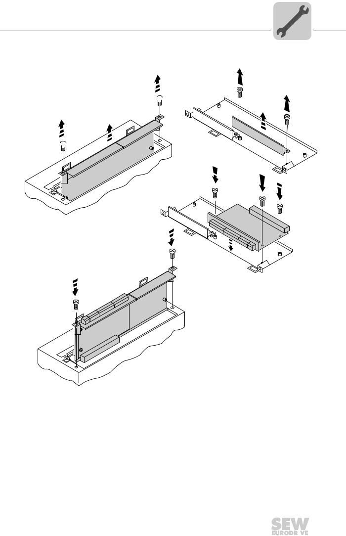
4.1.2Basic procedure for installing/removing an option card (MDX61B, sizes 1 – 6)
2.
1. 
2. 
1.
3.  3.
3. 
 3.
3.
4.
4.
60039AXX
1.Remove the two retaining screws holding the card retaining bracket. Pull the card retaining bracket out evenly from the slot (do not twist!).
2.Remove the two retaining screws of the black cover plate on the card retaining bracket. Remove the black cover plate.
3.Position the option card onto the retaining bracket so that the three retaining screws fit into the corresponding bores on the card retaining bracket.
4.Insert the retaining bracket with installed option card into the slot, pressing slightly so it is seated properly. Secure the card retaining bracket with the two retaining screws.
5.To remove the option card, follow the instructions in reverse order.
Phone: 800.894.0412 - Fax: 888.723.4773 - Web: www.clrwtr.com - Email: info@clrwtr.com
Manual – Fieldbus Interface DFE33B EtherNet/IP and Modbus/TCP |
|
|
13 |
|
|
|
|
|
|
|
|
|
|
|
|

4 |
Assembly and Installation Instructions |
Installing the DFE33B option card in MOVITRAC® B |
4.2Installing the DFE33B option card in MOVITRAC® B
TIP
Only SEW-EURODRIVE engineers are allowed to install or remove option cards for
MOVITRAC® B.
4.2.1Connecting the system bus between a MOVITRAC® B unit and the DFE33B option
|
|
DFE 33B |
|
|
|
|
|
S1 |
S2 |
|
STATUS |
|
|
|
MODULE |
NETWORK
STATUS
[1] ON
ON
[2] |
|
|
|
|
|
|
OFF |
|
|
|
|
|
X44 |
|
|
|
|
|
|
|
0B |
|
|||
|
|
|
|
|
|
|
|
|||||
|
|
FSC11B |
|
|
|
MAC ID: 00-0F-69-00-02- |
IP: |
|||||
X45 |
|
X46 |
|
|||||||
H |
L |
|
1 |
2 |
3 |
4 |
5 |
6 |
7 |
X30 |
|
||||||||||
|
|
|
|
|
|
|
|
|
|
X32 |
|
|
|
|
|
|
|
|
|
|
|
Def IP |
|
AS |
|
0 |
1 |
ETHERNET/IP
|
H1 |
|
H2 |
|
X24 |
X12 |
X26 |
1
2 1 2 3 4 5 6 7
3
+4
5
DC 24 V = |
|
|
|
|
6 |
|
– |
|
24V IO |
|
|
7 |
|
|
|
8 |
||||
|
|
|
||||
|
|
|
|
|
|
9 |
|
|
GND |
|
|
||
|
|
|
|
|
||
62135AXX
X46 |
X26 |
Terminal assignment |
X46:1 |
X26:1 |
SC11 SBus +, CAN high |
X46:2 |
X26:2 |
SC12 SBus –, CAN low |
X46:3 |
X26:3 |
GND, CAN GND |
|
X26:4 |
Reserved |
|
X26:5 |
Reserved |
X46:6 |
X26:6 |
GND, CAN GND |
X46:7 |
X26:7 |
DC 24 V |
|
|
|
X12 |
Terminal assignment |
X12:8 |
DC+24 V input |
X12:9 |
GND reference potential for binary inputs |
|
|
[1]Terminating resistor activated, S1 = ON
[2]DIP switch S2 (reserved), S2 = OFF
To simplify cabling, the DFE33B option can be supplied with DC 24 V from X46.7 of the MOVITRAC® B to X26.7. MOVITRAC® B must be supplied with DC 24 V at terminals X12.8 and X12.9 when it supplies the DFE33B option. Activate the system bus terminating resistor at the FSC11B option (S1 = ON).
Phone: 800.894.0412 - Fax: 888.723.4773 - Web: www.clrwtr.com - Email: info@clrwtr.com
14 |
|
|
Manual – Fieldbus Interface DFE33B EtherNet/IP and Modbus/TCP |
|
|
|
|
|
|
|
|
|
|
|
|
Assembly and Installation Instructions |
4 |
Installing the DFE33B option card in MOVITRAC® B |
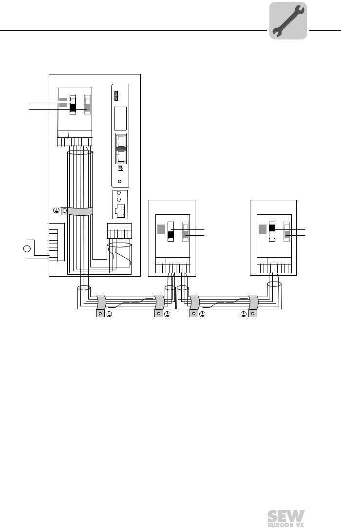
4.2.2Connecting the system bus between several MOVITRAC® B units
|
|
|
MOVITRAC® B |
|
|
|
|
|
|
|
||
|
|
|
|
|
DFE 33B |
|
|
|
|
|
||
|
|
|
S1 |
S2 |
|
MODULE |
|
|
|
|
|
|
|
|
|
|
|
|
STATUS |
|
|
|
|
|
|
|
|
|
|
|
|
NETWORK |
|
|
|
|
|
|
[1] |
|
|
ON |
|
|
STATUS |
|
|
|
|
|
|
|
|
|
|
|
|
|
|
|
|
|
||
[2] |
|
|
OFF |
|
|
|
|
|
|
|
|
|
|
X44 |
|
|
|
|
|
|
|
|
|
|
|
|
|
|
|
|
-00-02-0B |
|
|
|
|
|
|
|
|
|
|
|
|
MACID: |
|
|
|
|
|
|
|
|
|
FSC11B |
|
00-0F-69 |
IP: |
|
|
|
|
|
||
|
|
|
|
|
|
|
|
|
|
|
||
|
|
X45 |
X46 |
|
|
|
|
|
|
|
|
|
|
|
H L |
1 2 3 4 5 6 7 |
X30 |
|
|
|
|
|
|
|
|
|
|
|
|
|
|
|
|
|
|
|||
|
|
|
|
|
X32 |
|
|
|
|
|
|
|
|
|
|
|
|
Def IP |
|
|
|
|
|
|
|
|
|
|
|
|
AS |
|
|
|
|
|
|
|
|
|
|
|
|
|
0 |
1 |
|
|
|
|
|
|
|
|
|
|
ETHERNET/IP |
|
|
|
|
|
||
|
|
|
|
|
|
|
H1 |
|
|
|
|
|
|
|
|
|
|
|
|
H2 |
|
|
|
|
|
|
|
|
|
|
|
|
MOVITRAC® B |
MOVITRAC® B |
||||
|
|
|
|
|
X24 |
|
|
|
|
|
|
|
|
|
|
|
|
|
|
|
S1 |
S2 |
|
S1 |
S2 |
|
|
X12 |
|
|
X26 |
ON |
[1] |
|
ON |
[1] |
||
|
|
1 |
|
|
|
|
|
|
|
|
||
|
|
|
|
|
|
|
OFF |
[2] |
|
OFF |
[2] |
|
|
|
2 |
|
|
1 2 3 4 5 6 7 |
|
||||||
|
|
|
|
|
X44 |
|
||||||
|
|
3 |
|
|
|
|
X44 |
|
|
|
|
|
+ |
|
4 |
|
|
|
|
|
|
|
|
|
|
|
5 |
|
|
|
|
|
|
|
|
|
|
|
DC 24 V = |
|
6 |
|
|
|
|
FSC11B |
|
FSC11B |
|
||
- |
24V IO |
7 |
|
|
|
|
|
|
||||
|
|
8 |
|
|
|
|
|
|
|
|
|
|
|
GND |
9 |
|
|
|
|
X45 |
X46 |
|
X45 |
X46 |
|
|
|
|
|
|
|
|
|
|||||
|
|
|
|
|
|
|
H L 1 2 3 4 5 6 7 |
H L 1 2 3 4 5 6 7 |
||||
|
|
|
|
|
|
|
|
|
|
|
|
62136AXX |
[1]Only the terminating resistor at the last unit is activated, S1 = ON
[2]DIP switch S2 (reserved), S2 = OFF
MOVITRAC® B |
DFE33B in the UOH11B gateway housing |
||
X46 |
Terminal assignment |
X26 |
Terminal assignment |
X46:1 |
SC11 (System bus high, incoming) |
X26:1 |
SC11 SBus +, CAN high |
|
|
|
|
X46:2 |
SC12 (System bus low, incoming) |
X26:2 |
SC12 SBus –, CAN low |
|
|
|
|
X46:3 |
GND (System bus reference) |
X26:3 |
GND, CAN GND |
|
|
|
|
X46:4 |
SC21 (System bus high, outgoing) |
X26:4 |
Reserved |
|
|
|
|
X46:5 |
SC22 (System bus low, outgoing) |
X26:5 |
Reserved |
|
|
|
|
X46:6 |
GND (System bus reference) |
X26:6 |
GND, CAN GND |
|
|
|
|
X46:7 |
DC 24 V |
X26:7 |
DC 24 V |
|
|
|
|
X12 |
Terminal assignment |
X12:8 |
DC+24 V input |
|
|
X12:9 |
GND reference potential for binary inputs |
|
|
Phone: 800.894.0412 - Fax: 888.723.4773 - Web: www.clrwtr.com - Email: info@clrwtr.com
Manual – Fieldbus Interface DFE33B EtherNet/IP and Modbus/TCP |
|
|
15 |
|
|
|
|
|
|
|
|
|
|
|
|

4 |
Assembly and Installation Instructions |
Installing the DFE33B option card in MOVITRAC® B |
Please note:
•Use a 2x2 core twisted and shielded copper cable (data transmission cable with
braided copper shield). Connect the shield flatly on both sides of the electronics shield clamp of MOVITRAC®. Also connect the ends of the shield to GND. The cable must meet the following specifications:
–Core cross section 0.25 mm2 (AWG18) to 0.75 mm2 (AWG23)
–Cable resistance 120 Ê at 1 MHz
–Capacitance per unit length  40 pF/m at 1 kHz Suitable cables are CAN bus or DeviceNet cables.
•The permitted total cable length is 100 m (328 ft). The SBus baud rate has a fixed setting of 500 kBaud.
•Connect the system bus terminating resistor (S1 = ON) at the end of the system bus connection. Switch off the terminating resistor on the other units (S1 = OFF). The DFE33B gateway must always be connected either at the beginning or the end of the system bus connection. The terminating resistor is permanently installed.
TIPS
•There must not be any potential displacement between the units connected with the SBus. Take suitable measures to avoid potential displacement, such as connecting the unit ground connectors using a separate cable.
•Point-to-point SBus wiring is not permitted.
Phone: 800.894.0412 - Fax: 888.723.4773 - Web: www.clrwtr.com - Email: info@clrwtr.com
16 |
|
|
Manual – Fieldbus Interface DFE33B EtherNet/IP and Modbus/TCP |
|
|
|
|
|
|
|
|
|
|
|
|

Assembly and Installation Instructions |
4 |
Installing the DFE33B gateway / UOH11B |
4.3Installing the DFE33B gateway / UOH11B
The following figure shows the connection of the DFE33B option via the UOH11B gateway housing.
TIP
Only SEW-EURODRIVE engineers are allowed to install or remove option cards in/from the UOH11B gateway housing.
SC11 system bus +, CAN high SC12 system bus -, CAN low GND, CAN GND
UOH11B
DFE 33B
MODULE
STATUS
NETWORK
STATUS
MAC ID: 00-0F-69-00-02-0B |
IP: |
X32 X30
Def IP |
|
AS |
|
0 |
1 |
ETHERNET/IP |
|
|
H1 |
|
H2 |
X24 |
|
SEW Drive |
|
X26 |
|
1 2 3 4 5 6 7 |
|
|
DC+24 V |
|
GND |
62137AEN
UOH11B gateway housing
X26 |
Terminal assignment |
X26:1 |
SC11 system bus +, CAN high |
|
|
X26:2 |
SC12 system bus –, CAN low |
|
|
X26:3 |
GND, CAN GND |
|
|
X26:4 |
Reserved |
|
|
X26:5 |
Reserved |
|
|
X26:6 |
GND, CAN GND |
|
|
X26:7 |
DC 24 V |
|
|
The gateway housing requires a power supply of DC 24 V that is connected to X26. Connect the system bus terminating resistor at the end of the system bus connection.
Phone: 800.894.0412 - Fax: 888.723.4773 - Web: www.clrwtr.com - Email: info@clrwtr.com
Manual – Fieldbus Interface DFE33B EtherNet/IP and Modbus/TCP |
|
|
17 |
|
|
|
|
|
|
|
|
|
|
|
|
4 |
Assembly and Installation Instructions |
Connection and terminal description of the DFE33B option |
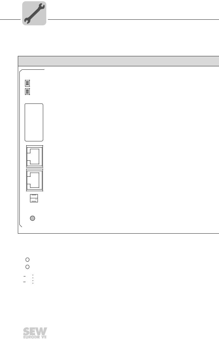
4.4Connection and terminal description of the DFE33B option
Part number |
EtherNet/IP and Modbus/TCP fieldbus interface option type DFE33B: 1821 346 4 |
Front view of
DFE33B
DFE 33B
MODULE
STATUS
NETWORK
STATUS
MAC ID: 00-0F-69-xx-xx-xx |
IP: |
X30
X32
Def IP 
AS 
0 1 ETHERNET/IP
62138AXX
Description |
DIP |
Function |
||
switch |
||||
|
|
|
||
MODULE STATUS LED |
|
Shows the current status of the DFE33B option. |
||
(red/green) |
|
|
|
|
NETWORK STATUS LED |
|
Shows the status of the controlling EtherNet/IP or Modbus/TCP |
||
(red/green) |
|
connection. |
||
MAC address |
|
MAC address, e.g. to configure the DHCP server. |
||
IP input field |
|
You can enter the allocated IP address in this field. |
||
X30: Ethernet connection |
|
|
|
|
Link LED (green) |
|
|
|
|
Activity LED (yellow) |
|
|
|
|
X32: Ethernet connection |
|
|
|
|
Link LED (green) |
|
|
|
|
Activity LED (yellow) |
|
|
|
|
|
|
|
||
DIP switch |
DEF IP |
Resets the address parameters to their default values and |
||
|
|
deactivates DHCP |
||
|
|
• |
IP address: 192.168.10.4 |
|
|
|
• |
Subnetwork mask: 255.255.255.0 |
|
|
|
• |
Gateway: 1.0.0.0 |
|
|
AS |
Auto Setup for gateway operation |
||
|
|
|
|
|
Front view of MOVITRAC® B |
Description |
Function |
|||||||
and UOH11B |
|||||||||
|
|
|
|||||||
|
|
|
|
|
H1 |
LED H1 |
(red) |
System bus error (only for gateway functions) |
|
|
|
|
|
|
|||||
|
|
|
|
|
H2 |
LED H2 |
(green) |
Reserved |
|
|
|
|
|
|
X24 |
X24 X terminal |
RS485 interface for diagnostics via PC and MOVITOOLS® |
||
|
|
|
|
|
|||||
|
|
|
|
|
|||||
|
|
|
|
|
58129AXX |
|
|
MotionStudio (only for MOVITRAC® B) |
|
|
|
|
|
|
|
|
|||
|
|
|
|
|
|
|
|
||
|
|
|
|
|
|
|
|
||
|
|
|
|
|
|
|
|
|
|
Phone: 800.894.0412 - Fax: 888.723.4773 - Web: www.clrwtr.com - Email: info@clrwtr.com
18 |
|
|
Manual – Fieldbus Interface DFE33B EtherNet/IP and Modbus/TCP |
|
|
|
|
|
|
|
|
|
|
|
|

Assembly and Installation Instructions |
4 |
Status LED of the DFE33B option |
4.5Status LED of the DFE33B option
The LEDs of the DFE33B option card indicate the current status of the DFE33B option and the fieldbus system.
DFE33B
MODULE
STATUS
NETWORK
STATUS
62139AXX
The fieldbus interface status indicated by the respective status LED is summarized in the section "Troubleshooting".
MODULE |
The MODULE STATUS LED indicates that the bus electronics are operating correctly. |
|
|
STATUS LED |
|
|
|
States of the |
Meaning |
|
|
|
|
||
|
MODULE STATUS LED |
|
|
|
Off |
The DFE33B option card is not supplied with voltage or is defective |
|
|
|
|
|
|
Flashing green |
• If the NETWORK STATUS LED is off at the same time, the TCP/IP stack |
|
|
|
of the DFE33B option card will be started. If this status continues and |
|
|
|
DHCP is activated, the DFE33B option card waits for data from the DHCP |
|
|
|
server. |
|
|
|
• If the NETWORK STATUS LED is flashing green at the same time, |
|
|
|
the application of the DFE33B option card is started. |
|
|
Flashing green/red |
The DFE33B option card performs a LED test. |
|
|
|
|
|
|
Green |
The standard operating state of the DFE33B option card. |
|
|
|
|
|
|
Red |
The DFE33B option card is in fault state. |
|
|
|
|
|
|
Flashing red |
A conflict has been detected in the IP address assignment. Another station in |
|
|
|
the network uses the same IP address. |
|
NETWORK |
The NETWORK STATUS LED indicates the state of the fieldbus system. |
|
|
STATUS LED |
|
|
|
States of the |
Meaning |
|
|
|
|
||
|
NETWORK STATUS LED |
|
|
|
Off |
The DFE33B option does not yet have any IP parameters. |
|
|
|
|
|
|
Flashing green/red |
The DFE33B option card performs a LED test. |
|
|
|
|
|
|
Flashing green |
There is no controlling IO connection. |
|
|
|
|
|
|
Green |
There is a controlling EtherNet/IP or Modbus/TCP connection. |
|
|
|
|
|
|
Red |
A conflict has been detected in the IP address assignment. |
|
|
|
Another station in the network uses the same IP address. |
|
|
|
|
|
|
Flashing red |
The previously established controlling IO connection is in timeout status. |
|
|
|
The status is reset by restarting communication. |
|
Phone: 800.894.0412 - Fax: 888.723.4773 - Web: www.clrwtr.com - Email: info@clrwtr.com
Manual – Fieldbus Interface DFE33B EtherNet/IP and Modbus/TCP |
|
|
19 |
|
|
|
|
|
|
|
|
|
|
|
|

4 |
Assembly and Installation Instructions |
Status LED of the DFE33B option |
Link/Activity LED The two LEDs Link (green) and Activity (yellow), integrated in the RJ45 plug connectors (X30, X32), display the status of the Ethernet connection.
LED "Link"
LED "Activity"
X32 X30


61880AXX
LED / status |
Meaning |
Link / green |
There is an Ethernet connection. |
|
|
Activity / yellow |
Data is currently being exchanged via Ethernet. |
|
|
Link / off |
There is no Ethernet connection. |
|
|
Link (X30) / flashes |
Locating function of Address Editor (see section 10) |
|
|
TIP
As the firmware of the DFE33B option card takes approx. 15 seconds for initialization, the status "0" (inverter not ready) is displayed in the 7-segment display of MOVIDRIVE® during this time.
4.5.1Gateway LED
LEDs H1 and H2 indicate the communication status in gateway operation.
H1
H2
X24
58129AXX
LED H1 Sys-fault (red) |
|
Only for gateway operation |
|
Status |
State |
|
Description |
Red |
System bus error |
|
Gateway not configured or one of the drives |
|
|
|
is inactive |
|
|
|
|
Off |
SBus ok |
|
Gateway is configured correctly |
|
|
|
|
Flashing |
Bus scan |
|
Bus is being checked by the gateway |
|
|
|
|
•LED H2 (green) is currently reserved.
•X-terminal X24 is the RS485 interface for diagnostics via PC and MOVITOOLS® MotionStudio.
Phone: 800.894.0412 - Fax: 888.723.4773 - Web: www.clrwtr.com - Email: info@clrwtr.com
20 |
|
|
Manual – Fieldbus Interface DFE33B EtherNet/IP and Modbus/TCP |
|
|
|
|
|
|
|
|
|
|
|
|
Assembly and Installation Instructions |
4 |
Pin assignment |
4.6Pin assignment
Use prefabricated, shielded RJ45 plug connectors compliant with IEC 11801 edition 2.0, category 5.
[6] [3] [2] [1]
6
|
3 |
2 |
|
1 |
|
A B
54174AXX
Fig. 1: Pin assignment of an RJ45 plug connector
A = Front view
B = View from back
[1]Pin 1 TX+ Transmit Plus
[2]Pin 2 TX– Transmit Minus
[3]Pin 3 RX+ Receive Plus
[6]Pin 6 RX– Receive Minus
MOVIDRIVE® / MOVITRAC® B / Ethernet connection
To connect DFE33B to the Ethernet, connect the Ethernet interface X30 or X32 (RJ45 plug connector) to the other network stations using a category 5, class D twisted-pair cable in accordance with IEC 11801 edition 2.0. The integrated switch provides support for achieving a line topology and offers auto-crossing functions.
TIPS
•According to IEC 802.3, the maximum cable length for 10/100 MBaud Ethernet (10BaseT / 100BaseT), e.g. between two network stations, is 100 m.
•We recommend that you do not directly connect terminals to the DFE33B option in order to minimize the load on the terminals caused by undesired multicast data traffic in EtherNet/IP networks. Connect non-SEW devices via a network component that supports the IGMP snooping functionality (e.g. managed switch).
Phone: 800.894.0412 - Fax: 888.723.4773 - Web: www.clrwtr.com - Email: info@clrwtr.com
Manual – Fieldbus Interface DFE33B EtherNet/IP and Modbus/TCP |
|
|
21 |
|
|
|
|
|
|
|
|
|
|
|
|

4 |
Assembly and Installation Instructions |
The integrated Ethernet switch |
4.7The integrated Ethernet switch
You can use the integrated Ethernet switch to achieve line topologies known from the fieldbus technology. Other bus topologies such as star or tree are, of course, also possible. Ring topologies are not supported.
TIP
The number of industrial Ethernet switches connected in line affects the telegram runtime. If a telegram passes through the units, the telegram runtime is delayed by the Store & Forward function of the Ethernet switch:
•for a telegram length of 64 bytes by approximately 10 µs (at 100 Mbit/s)
•for a telegram length of 1500 bytes by approximately 130 µs (at 100 Mbit/s)
This means, the more units that the telegram has to run through, the longer the telegram runtime.
Auto-crossing |
The two ports leading out of the Ethernet switch have auto-crossing functionality. This |
|
means you can use both patch cables and cross-over cables to connect to the next |
|
Ethernet station. |
Autonegotiation |
The baud rate and the duplex mode is negotiated by both Ethernet nodes when estab- |
|
lishing the connection. The two Ethernet ports of the EtherNet/IP interface support auto- |
|
negotiation functionality and operate at a baud rate of 100 Mbit or 10 Mbit in full duplex |
|
or half duplex mode. |
Notes on |
• The integrated Ethernet switch offers no filter functionality for Ethernet multicast tele- |
multicast |
grams. Multicast telegrams that are usually sent from the adapters (DFE33B) to the |
handling |
scanners (PLC) are passed on to all switch ports. |
•IGMP snooping (e.g. managed switches) is not supported.
•SEW-EURODRIVE therefore recommends to connect the DFE33B option only with network components that support IGMP snooping (e.g. managed switch) or that have safety mechanisms integrated against excess multicast load (e.g. units from SEWEURODRIVE). Units that do not have this integrated function can fail due to high network loads.
4.8Shielding and routing bus cables
Only use shielded cables and connection elements that also meet the requirements of category 5, class 2 in compliance with IEC 11801 edition 2.0.
Correct shielding of the bus cable attenuates electrical interference that can occur in industrial environments. The following measures ensure the best possible shielding:
•Manually tighten the mounting screws on the connectors, modules, and equipotential bonding conductors.
•Use only connectors with a metal housing or a metallic housing.
•Connect the shielding in the connector over a wide surface area.
•Apply the shielding of the bus line on both ends.
•Route signal and bus cables in separate cable ducts. Do not route them parallel to power cables (motor leads).
Phone: 800.894.0412 - Fax: 888.723.4773 - Web: www.clrwtr.com - Email: info@clrwtr.com
22 |
|
|
Manual – Fieldbus Interface DFE33B EtherNet/IP and Modbus/TCP |
|
|
|
|
|
|
|
|
|
|
|
|
Assembly and Installation Instructions |
4 |
Setting the DIP switches |
•Use metallic, grounded cable racks in industrial environments.
•Route the signal cable and the corresponding equipotential bonding close to each other using the shortest possible route.
•Avoid using plug connectors to extend bus cables.
•Route the bus cables closely along existing grounding surfaces.
STOP!
In case of fluctuations in the ground potential, a compensating current may flow via the bilaterally connected shield that is also connected to the protective earth (PE). Make sure you supply adequate equipotential bonding in accordance with relevant VDE regulations in such a case.
4.9Setting the DIP switches
TIP
The setting of the "Def IP" DIP switch is only adopted with a power-on reset (switching mains and DC 24 V backup voltage on and off).
Def IP |
When the "Def IP" switch is set to "1" (= ON), the following default IP address parame- |
|
|
ters are set when activating the DC 24 V backup voltage: |
|
|
• |
IP address: 192.168.10.4 |
|
• |
Subnetwork mask: 255.255.255.0 |
|
• |
Default gateway: 1.0.0.0 |
|
• P785 DHCP / Startup configuration: Saved IP parameters (DHCP is deactivated) |
|
AS |
The "AS" DIP switch is used to configure the SBus communication of the gateway |
|
|
(see section "Auto Setup for gateway operation"). |
|
The configuration becomes active when the "AS" DIP switch is set from "0" to "1".
To continue operation, the "AS" DIP switch must remain in the "1" position (= ON).
Phone: 800.894.0412 - Fax: 888.723.4773 - Web: www.clrwtr.com - Email: info@clrwtr.com
Manual – Fieldbus Interface DFE33B EtherNet/IP and Modbus/TCP |
|
|
23 |
|
|
|
|
|
|
|
|
|
|
|
|

4 |
Assembly and Installation Instructions |
TCP/IP addressing and subnetworks |
4.10TCP/IP addressing and subnetworks
Introduction |
The settings for the address of the IP protocol are made using the following parameters: |
|
|
• |
MAC address |
|
• |
IP address |
|
• |
Subnetwork mask |
|
• |
Standard gateway |
|
The addressing mechanisms and subdivision of the IP networks into subnetworks are |
|
|
explained in this chapter to help you set the parameters correctly. |
|
MAC address |
The MAC address (Media Access Controller) is the basis for all address settings. The |
|
|
MAC address is a worldwide unique 6-byte value (48 bits) assigned to the Ethernet |
|
|
device. SEW Ethernet devices have the MAC address 00-0F-69-xx-xx-xx. The MAC |
|
|
address is difficult to handle for larger networks. This is why freely assignable IP |
|
|
addresses are used. |
|
IP address |
The IP address is a 32 bit value that uniquely identifies a station in the network. An IP |
|
address is represented by four decimal numbers separated by decimal points. Example: 192.168.10.4
Each decimal number stands for one byte (= 8 bits) of the address and can also be represented using binary code (Æ following table).
Byte 1 |
|
Byte 2 |
|
Byte 3 |
|
Byte 4 |
11000000 |
. |
10101000 |
. |
00001010 |
. |
00000100 |
|
|
|
|
|
|
|
The IP address comprises a network address and a station address (Æ following table).
Network address |
Station address |
192.168.10 |
4 |
|
|
The part of the IP address that denotes the network and the part that identifies the station is determined by the network class and the subnetwork mask.
Station addresses cannot consist of only zeros or ones (binary) because they represent the network itself or a broadcast address.
Network classes The first byte of the IP address determines the network class and as such represents the division into network addresses and station addresses.
Value range |
Network class |
Complete network address |
Meaning |
|
Byte 1 |
(Example) |
|||
|
|
|||
0 ... 127 |
A |
10.1.22.3 |
10 = Network address |
|
|
|
|
1.22.3 = Station address |
|
128 ... 191 |
B |
172.16.52.4 |
172.16 = Network address |
|
|
|
|
52.4 = Station address |
|
|
|
|
|
|
192 ... 223 |
C |
192.168.10.4 |
192.168.10 = Network address |
|
|
|
|
4 = Station address |
|
|
|
|
|
This rough division is not sufficient for a number of networks. They also use an explicit, adjustable subnet mask.
Phone: 800.894.0412 - Fax: 888.723.4773 - Web: www.clrwtr.com - Email: info@clrwtr.com
24 |
|
|
Manual – Fieldbus Interface DFE33B EtherNet/IP and Modbus/TCP |
|
|
|
|
|
|
|
|
|
|
|
|

Assembly and Installation Instructions |
4 |
TCP/IP addressing and subnetworks |
Subnetwork A subnetwork mask is used to divide the network classes into even more precisely mask defined subsections. The subnetwork mask is represented by four decimal numbers separated by decimal points, in the same way as the IP address.
Example: 255.255.255.128
Each decimal number stands for one byte (= 8 bits) of the subnetwork mask and can also be represented using binary code (Æ following table).
Byte 1 |
|
Byte 2 |
|
Byte 3 |
|
Byte 4 |
11111111 |
. |
11111111 |
. |
11111111 |
. |
10000000 |
|
|
|
|
|
|
|
If you compare the IP addresses with the subnetwork masks, you see that in the binary representation of the subnetwork mask all ones (1s) determine the network address and all the zeros (0s) determine the station address (Æ following table).
|
|
Byte 1 |
|
Byte 2 |
|
Byte 3 |
|
Byte 4 |
|
IP address |
Decimal |
192 |
. |
168. |
. |
10 |
. |
129 |
|
|
|
|
|
|
|
|
|
||
Binary |
11000000 |
. |
10101000 |
. |
00001010 |
. |
10000001 |
||
|
|||||||||
|
|
|
|
|
|
|
|
|
|
Subnetwork mask |
Decimal |
255 |
. |
255 |
. |
255 |
. |
128 |
|
Binary |
11111111 |
. |
11111111 |
. |
11111111 |
. |
10000000 |
||
|
|||||||||
|
|
|
|
|
|
|
|
|
The class C network with the address 192.168.10. is further subdivided into 255.255.255.128 using the subnetwork mask. Two networks are created with the address 192.168.10.0 and 192.168.10.128.
The following station addresses are permitted in the two networks:
•192.168.10.1 ... 192.168.10.126
•192.168.10.129 ... 192.168.10.254
The network stations use a logical AND operation for the IP address and the subnetwork mask to determine whether there is a communication partner in the same network or in a different network. If the communication partner is in a different network, the standard gateway is addressed for passing on the data.
Standard gateway |
The standard gateway is also addressed via a 32-bit address. The 32-bit address is |
|
represented by four decimal numbers separated by decimal points. |
|
Example: 192.168.10.1 |
|
The standard gateway establishes a connection to other networks. In this way, a net- |
|
work station that wants to address another station can use a logical AND operation with |
|
the IP address and the subnetwork mask to decide whether the desired station is located |
|
in the same network. If this is not the case, the station addresses the standard gateway |
|
(router), which must be part of the actual network. The standard gateway then takes on |
|
the job of transmitting the data packages. |
DHCP |
Instead of setting the three parameters IP address, subnetwork mask and standard |
(Dynamic Host |
gateway manually, they can be assigned in an automated manner by a DHCP server in |
Configuration |
the Ethernet network. |
Protocol) |
This means the IP address is assigned from a table, which contains the allocation of |
|
MAC address to IP address. |
|
Parameter P785 indicates whether the DFE33B option expects the IP parameters to be |
|
assigned manually or via DHCP. |
Phone: 800.894.0412 - Fax: 888.723.4773 - Web: www.clrwtr.com - Email: info@clrwtr.com
Manual – Fieldbus Interface DFE33B EtherNet/IP and Modbus/TCP |
|
|
25 |
|
|
|
|
|
|
|
|
|
|
|
|
4 |
Assembly and Installation Instructions |
Setting the IP address parameters |
4.11Setting the IP address parameters
Initial startup |
The "DHCP" protocol (Dynamic Host Configuration Protocol) is activated as the default |
|
setting for the DFE33B protocol. This means that the DFE33B option card expects its IP |
|
address parameters from a DHCP server. |
TIP
Rockwell Automation provides a DHCP server free-of-charge on their homepage.
The tool is known as "BOOTP Utility" and can be downloaded at the link below:
Once the DHCP server has been configured and the settings have been made for the subnetwork screen and the standard gateway, the DFE33B must be inserted in the assignment list of the DHCP server. In doing so, the MAC ID of the DFE33B option is
allocated a valid IP address.
TIP
The configured IP address parameters are adopted permanently by the parameter set
when DHCP is deactivated after the IP address has been assigned.
Changing the IP address parameters after
successful initial startup
If the DFE33B was started using a valid IP address, you can also access the IP address parameters via the Ethernet interface.
The following options are available for changing the IP address parameters via Ethernet:
•Via the homepage of DFE33B (see section "Integrated Web Server")
•Using the MOVITOOLS® MotionStudio software via Ethernet (see section "MOVITOOLS® MotionStudio via Ethernet")
•Using the EtherNet/IP TCP/IP interface object (see section "EtherNet/IP CIP object directory")
You can also change the IP address parameters via the serial interface of the gateway or MOVIDRIVE® MDX61B or using the DBG60B keypad (in MOVIDRIVE® B).
If the IP address parameters are assigned to the option DFE33B via a DHCP server, you can only change the parameters by adjusting the settings of the DHCP server.
The options listed above for changing the IP address parameters only come into effect once the supply voltages (mains and DC 24 V) have been switched off and back on again.
Phone: 800.894.0412 - Fax: 888.723.4773 - Web: www.clrwtr.com - Email: info@clrwtr.com
26 |
|
|
Manual – Fieldbus Interface DFE33B EtherNet/IP and Modbus/TCP |
|
|
|
|
|
|
|
|
|
|
|
|
Assembly and Installation Instructions |
4 |
Setting the IP address parameters |
Deactivating / |
The type of IP address assignment is determined by the setting of the attribute |
|
activating the |
Configuration Control of the EtherNet/IP TCP/IP interface object. The value is displayed |
|
DHCP |
or changed in the parameter P785 DHCP / Startup Configuration. |
|
|
• Setting "Saved IP parameters" |
|
|
|
The saved IP address parameters are used. |
|
• |
Setting "DHCP" |
|
|
The IP address parameters are requested by a DHCP server. |
|
|
If you use the DHCP server from Rockwell Automation, you can activate or deacti- |
|
|
vate the DHCP via a button. In this case, an EtherNet/IP telegram is sent to the |
|
|
TCP/IP interface object of the station that is being addressed. |
Resetting the |
If you do not know the IP address parameters and there is no serial interface or DBG60B |
|
IP address |
keypad for reading the IP address, you can reset the IP address parameters to the |
|
parameters |
default values using the DIP switch "Def IP". |
|
|
This action resets the DFE33B option to the following default values: |
|
|
• |
IP address: 192.168.10.4 |
|
• |
Subnetwork mask: 255.255.255.0 |
|
• |
Default gateway: 1.0.0.0 |
• P785 DHCP / Startup configuration: Saved IP parameters (DHCP is deactivated)
Proceed as follows to reset the IP address parameters to the default values:
•Switch off the DC 24 V supply voltage and the mains voltage.
•Set the DIP switch "Def IP" on the DFE33B option to "1".
•Switch the DC 24 V supply voltage and the mains voltage back on.
SEW Address To access the IP settings of the DFE33B interfaces without the Ethernet settings of the Editor PC and DFE33B having to match, the SEW Address Editor can be used if firmware
version .11 or higher is installed on the DFE33B.
The IP settings of all SEW units can be made and displayed in the local subnetwork using Address Editor (see section 10).
•This allows the required settings for the PC to be determined for an installation which is in operation to enable access with the required diagnostics and engineering tools via Ethernet.
•When starting up a unit, the IP settings for the DFE33B can be assigned without changing the network connections or PC settings.
TIP
•DHCP remains deactivated when you reset the DIP switch "Def IP" to "0". You can re-activate DHCP via the EtherNet/IP TCP/IP interface object (see section "EtherNet/IP CIP object directory"), via the parameter P785, via the integrated web server or via the DHCP server from Rockwell.
•DHCP is not activated again when the values are reset to the factory setting (P802 Factory setting).
Phone: 800.894.0412 - Fax: 888.723.4773 - Web: www.clrwtr.com - Email: info@clrwtr.com
Manual – Fieldbus Interface DFE33B EtherNet/IP and Modbus/TCP |
|
|
27 |
|
|
|
|
|
|
|
|
|
|
|
|

4 |
Assembly and Installation Instructions |
Procedure for replacing the unit |
4.12Procedure for replacing the unit
If the DIP switch "Def IP" of the DFE33B option is set to "1" (= ON), the DIP switch "Def IP" on the new DFE33B must also be set to "1" (= ON) (after the option card has been replaced or after the MOVIDRIVE® B / MOVITRAC® B / gateway housing unit have each been replaced with an option card). Other IP parameter settings are not required.
If the DIP switch "Def IP" of the DFE33B option is set to "0" (= OFF), it is important that you observe the following section when replacing the option card or a unit with option card:
•Section "Replacing MOVIDRIVE® B"
•Section "Replacing MOVITRAC® B / gateway"
4.12.1Replacing MOVIDRIVE® B
When the DFE33B fieldbus interface is operated as an option card in MOVIDRIVE® B, the procedure for replacement depends on the following factors:
•Whether DHCP is activated or a saved IP address is used
•Whether the memory card of the replaced MOVIDRIVE® MDX61B is plugged into the new unit or not
If DHCP is active, the assignment list of the DHCP server must be updated when the DFE33B option or MOVIDRIVE® B with DFE33B option is replaced. The MAC address of the DFE33B option is printed on its front panel for this purpose.
If DHCP is not active, the IP parameters saved on the memory card of MOVIDRIVE® B will be used.
If the memory card of MOVIDRIVE® B is not plugged into the new unit when replacing it, you will have to perform complete startup of the new inverter (if DHCP is not active including the IP parameters). As an alternative, you can transfer a data backup created with the MOVITOOLS® MotionStudio software or saved in the DBG60B keypad.
Enter the IP address, which is set in the DFE33B or defined in the assignment list of the DHCP server, into the field on the front panel of the DFE33B option for future diagnostic or engineering work.
Phone: 800.894.0412 - Fax: 888.723.4773 - Web: www.clrwtr.com - Email: info@clrwtr.com
28 |
|
|
Manual – Fieldbus Interface DFE33B EtherNet/IP and Modbus/TCP |
|
|
|
|
|
|
|
|
|
|
|
|

Assembly and Installation Instructions |
4 |
Procedure for replacing the unit |
4.12.2 Replacing MOVITRAC® B / gateway
If the DFE33B fieldbus interface is operated as an option card in MOVITRAC® B or in the UOH11B gateway housing, the procedure for replacement depends on the following factors:
•Whether DHCP is activated or a saved IP address is used
•Whether the DFE33B option is installed in MOVITRAC® B or in the gateway housing
If DHCP is active, the assignment list of the DHCP server must be updated when the DFE33B option or MOVITRAC® B with DFE33B option is replaced. The MAC address of the DFE33B option is printed on its front panel for this purpose.
If DHCP is not active, the IP parameters saved non-volatile on the DFE33B option will be used. Set the IP parameters just as for initial startup. As an alternative, you can copy a parameter file saved with MOVITOOLS® MotionStudio (from version 5.50, service pack 2) to the DFE33B option or use the Address
Editor to set the IP parameters.
If a MOVITRAC® B with DFE33B was replaced by a new unit, inverter startup will have to be performed in addition to setting the IP parameters. Refer to the MOVITRAC® B operating instructions for more information.
Enter the IP address, which is set in the DFE33B or defined in the assignment list of the DHCP server, into the field on the front panel of the DFE33B option for future diagnostic or engineering work.
Phone: 800.894.0412 - Fax: 888.723.4773 - Web: www.clrwtr.com - Email: info@clrwtr.com
Manual – Fieldbus Interface DFE33B EtherNet/IP and Modbus/TCP |
|
|
29 |
|
|
|
|
|
|
|
|
|
|
|
|

5 |
|
Project Planning and Startup (EtherNet/IP) |
|
Validity of the EDS file for DFE33B |
|
|
|
|
|
|
|
5 Project Planning and Startup (EtherNet/IP)
This section provides information on project planning for the EtherNet/IP master and startup of the inverter for fieldbus operation. As a prerequisite, the connection and setting of the IP address parameters of DFE33B must be correct according to the section "Assembly and Installation Instructions".
5.1Validity of the EDS file for DFE33B
TIP
Do not change or expand the entries in the EDS file. SEW assumes no liability for inverter malfunctions caused by a modified EDS file!
SEW-EURODRIVE provides two different EDS files for configuring the scanner (EtherNet/IP master).
•If the DFE33B option is installed in MOVIDRIVE® B, the file SEW_MOVIDRIVE_ DFE33B.eds is required
•If the DFE33B option is used as a gateway in MOVITRAC® B or in the gateway housing (UOH11B), the file SEW_GATEWAY_DFE33B.eds is required
TIP
Current versions of the EDS files for the DFE33B option are available on the SEW homepage under the heading "Software".
Phone: 800.894.0412 - Fax: 888.723.4773 - Web: www.clrwtr.com - Email: info@clrwtr.com
30 |
|
|
Manual – Fieldbus Interface DFE33B EtherNet/IP and Modbus/TCP |
|
|
|
|
|
|
|
|
|
|
|
|
 Loading...