


Gearmotors \ Industrial Gear Units \ Drive Electronics \ Drive Automation \ Services
DFE32B PROFINET IO
Fieldbus Interface
Edition 09/2007
11614226 / EN
Manual

SEW-EURODRIVE – Driving the world
Phone: 800.894.0412 - Fax: 888.723.4773 - Web: www.clrwtr.com - Email: info@clrwtr.com

|
|
|
|
|
|
|
|
|
|
|
|
|
|
|
|
|
|
|
|
|
|
|
|
|
|
|
|
|
|
|
|
|
|
|
|
|
|
|
|
|
|
|
|
|
|
|
|
|
|
|
|
|
|
|
|
|
|
|
|
|
|
|
|
|
|
|
|
|
|
|
|
|
|
|
|
|
|
|
|
|
|
|
|
|
|
|
|
|
|
|
|
|
|
|
|
|
|
|
|
|
|
|
|
|
|
|
|
|
|
|
|
.........................................................................................................1 General Notes |
6 |
|||||
1.1 |
Structure of the safety notes .......................................................................... |
6 |
||||
1.2 |
Right to claim under warranty ........................................................................ |
6 |
||||
1.3 |
Exclusion of liability........................................................................................ |
6 |
||||
2 Safety Notes ........................................................................................................... |
7 |
|
2.1 |
Other applicable documentation .................................................................... |
7 |
2.2 |
General safety notes for bus systems............................................................ |
7 |
2.3 |
Safety functions ............................................................................................. |
7 |
2.4 |
Hoist applications........................................................................................... |
7 |
2.5 |
Product names and trademarks..................................................................... |
7 |
2.6 |
Waste disposal............................................................................................... |
8 |
3 Introduction |
............................................................................................................ |
|
|
9 |
|
3.1 |
Content of the manual.................................................................................... |
|
|
9 |
|
3.2 |
Additional documentation............................................................................... |
|
|
9 |
|
3.3 |
Features......................................................................................................... |
|
|
9 |
|
|
3.3.1 |
® |
® |
B and PROFINET |
9 |
|
MOVIDRIVE B, MOVITRAC |
|
|||
|
3.3.2 Access to all information ................................................................... |
|
|
10 |
|
|
3.3.3 |
Monitoring functions .......................................................................... |
|
|
10 |
|
3.3.4 |
Diagnostics ....................................................................................... |
|
|
10 |
|
3.3.5 |
Fieldbus monitor ............................................................................... |
|
|
10 |
4 Assembly and Installation Notes |
........................................................................ |
11 |
|||
4.1 |
Installing the DFE32B option .....................card in MOVIDRIVE® MDX61B |
11 |
|||
|
4.1.1 |
Before you begin ............................................................................... |
|
12 |
|
|
4.1.2 |
Basic |
procedurefor installing and removing an option card |
|
|
|
|
(MDX61B, BG 1 - 6) .......................................................................... |
|
13 |
|
4.2 |
Installing the DFE32B option .................................card in MOVIDRIVE® B |
14 |
|||
|
4.2.1 |
Connecting a system bus (SBus 1) between a MOVITRAC® B |
|
||
|
|
and the DFE32B option .................................................................... |
14 |
||
|
4.2.2 |
Connecting system bus (SBus 1) between several |
|
||
|
|
MOVITRAC® B units ......................................................................... |
|
15 |
|
4.3 |
Installing the DFE32B/UOH11B .....................................................gateway |
17 |
|||
4.4 |
Connection and terminal description ..................................DFE32B option |
18 |
|||
4.5 |
Pin assignment ............................................................................................ |
|
19 |
||
4.6 |
Shielding and routing bus cables ................................................................. |
20 |
|||
4.7 |
TCP / IP addressing and subnetworks......................................................... |
21 |
|||
4.8 |
Setting the IP address parameters ................................................via DCP |
23 |
|||
4.9 |
Procedure after device replacement ............................................................ |
24 |
|||
|
4.9.1 |
Device |
replacement |
® |
24 |
|
MOVIDRIVE B |
||||
|
4.9.2 |
Device |
replacement |
® |
24 |
|
MOVITRAC B / gateway |
||||
4.10 |
Operating display DFE32B option................................................................ |
25 |
|||
|
4.10.1 PROFINET-LEDs ............................................................................. |
|
25 |
||
|
4.10.2 Gateway LED ................................................................................... |
|
26 |
||
5 Project Planning with PROFINET........................................................................ |
28 |
|
5.1 |
Project planning for the PROFINET IO controller ........................................ |
28 |
|
5.1.1 Assigning the PROFINET device name ............................................ |
29 |
|
5.1.2 Project planning for the PROFINET interface for MOVIDRIVE® B ... |
31 |
|
5.1.3 Project planning for MOVITRAC® B or gateway with |
|
|
DFE32B option ................................................................................. |
37 |
|
5.1.4 Project planning for the PROFINET interface for MOVITRAC® B .... |
38 |
5.2 |
Auto setup for gateway operation ................................................................ |
44 |
5.3 |
Setting the MOVIDRIVE® MDX61B drive inverter ....................................... |
46 |
Phone: 800.894.0412 - Fax: 888.723.4773 - Web: www.clrwtr.com - Email: info@clrwtr.com
Manual – DFE32B PROFINET IO Fieldbus Interface |
|
|
3 |
|
|
|
|
|
|
|
|
|
|
|
|

|
|
|
|
|
|
|
|
|
|
|
|
|
|
|
|
|
|
|
|
|
|
|
|
|
|
|
|
|
|
|
|
|
|
|
|
|
|
|
|
|
|
|
|
|
|
|
|
|
|
|
|
|
|
|
|
|
|
|
|
|
|
|
|
|
|
|
|
|
|
|
|
|
|
|
|
|
|
|
|
|
|
|
|
|
|
|
|
|
|
|
|
|
|
|
|
|
|
|
|
|
|
|
|
|
|
|
|
|
|
|
|
|
|
|
|
|
|
|
|
|
|
|
|
|
|
|
|
|
|
|
|
|
|
|
|
|
|
|
|
|
|
|
|
|
|
|
|
|
|
|
|
|
|
|
|
|
|
|
|
|
|
|
|
|
|
|
|
|
|
|
|
|
|
|
5.4 |
Setting the MOVITRAC® B frequency inverter |
47 |
|
|||
|
|
|
|
|
|
|
||||||
|
|
|
|
|
|
|
||||||
|
|
|
|
|
|
|
||||||
|
|
|
|
|
|
5.5 |
Startup procedure for MDX61B with DFE32B option................................... |
48 |
|
|||
|
|
|
|
|
|
|
5.5.1 |
Preliminary |
work ............................................................................... |
48 |
||
|
|
|
|
|
|
|
5.5.2 |
Starting up |
® |
48 |
|
|
|
|
|
|
|
|
|
MOVIDRIVE B with DC 24 V or AC 400 V ................... |
|
||||
|
|
|
|
|
|
5.6 |
Startup procedure for the DFE32B option as gateway................................. |
50 |
|
|||
|
|
|
|
|
|
|
5.6.1 |
Preliminary |
work ............................................................................... |
50 |
||
|
|
|
|
|
|
|
5.6.2 |
Starting up units with DC 24 V or AC 400 V ..................................... |
51 |
|
||
6 |
PROFINET Operating Behavior........................................................................... |
53 |
|
|||||||||
|
|
|
|
|
|
6.1 |
Introduction .................................................................................................. |
|
|
53 |
|
|
|
|
|
|
|
|
6.2 |
The integrated Ethernet switch .................................................................... |
55 |
|
|||
|
|
|
|
|
|
6.3 |
Process data configuration .......................................................................... |
56 |
|
|||
|
|
|
|
|
|
6.4 |
Controlling the MOVIDRIVE® MDX61B drive inverter ................................. |
57 |
|
|||
|
|
|
|
|
|
|
6.4.1 |
Control example MATICSI S7 with MOVIDRIVE® MDX61B ............. |
58 |
|
||
|
|
|
|
|
|
|
6.4.2 |
|
|
® |
58 |
|
|
|
|
|
|
|
|
PROFINET timeout (MOVIDRIVEMDX61B) .................................. |
|
||||
|
|
|
|
|
|
|
6.4.3 |
Fieldbus timeout response (MOVIDRIVE® MDX61B) ....................... |
58 |
|
||
|
|
|
|
|
|
6.5 |
Controlling the MOVITRAC® B (gateway) frequency inverter...................... |
59 |
|
|||
|
|
|
|
|
|
|
6.5.1 |
Control example for SIMATIC S7 with MOVITRAC® B (gateway) .... |
60 |
|
||
|
|
|
|
|
|
|
6.5.2 |
SBus |
timeout .................................................................................... |
60 |
||
|
|
|
|
|
|
|
6.5.3 |
Unit |
error |
........................................................................................... |
60 |
|
|
|
|
|
|
|
|
6.5.4 Fieldbus timeout .....response of the DFE32B in gateway operation |
60 |
|
|||
|
|
|
|
|
|
6.6 |
SIMATIC S7 Sample ......................................................................program |
61 |
|
|||
|
|
|
|
|
|
6.7 |
PROFINET alarms ..........................using the example of MOVIDRIVE® B |
62 |
|
|||
7 |
Configuration via PROFIdrive .........................................................Data Set 47 |
64 |
|
|||||||||
|
|
|
|
|
|
7.1 |
Introducing PROFINET .................................................................data sets |
64 |
|
|||
|
|
|
|
|
|
|
7.1.1 |
Features of the ......................SEW-EURODRIVE PROFINET units |
65 |
|
||
|
|
|
|
|
|
7.2 |
Structure of the PROFINET ..........................................parameter channel |
66 |
|
|||
|
|
|
|
|
|
|
7.2.1 Parameter setting ....................................procedure via data set 47 |
67 |
|
|||
|
|
|
|
|
|
|
7.2.2 |
Controller processing .......................................................sequence |
68 |
|||
|
|
|
|
|
|
|
7.2.3 |
Addressing connected ........................................................inverters |
69 |
|
||
|
|
|
|
|
|
|
7.2.4 |
|
® |
parameter requests |
70 |
|
|
|
|
|
|
|
|
MOVILINK ...................................................... |
|
||||
|
|
|
|
|
|
|
7.2.5 |
PROFIdrive ....................................................... |
parameter requests |
75 |
||
|
|
|
|
|
|
7.3 |
Read or write parameters ....................................................via data set 47 |
80 |
|
|||
|
|
|
|
|
|
|
7.3.1 |
Sample program .....................................................for SIMATIC S7 |
80 |
|
||
|
|
|
|
|
|
|
7.3.2 |
Technical data ....................PROFINET for MOVIDRIVE® DFE32B |
80 |
|
||
|
|
|
|
|
|
|
7.3.3 Error codes of ............................................the PROFINET services |
81 |
||||
8 |
Integrated Web Server ......................................................................................... |
|
82 |
|
||||||||
|
|
|
|
|
|
8.1 |
Software requirements................................................................................. |
82 |
||||
|
|
|
|
|
|
8.2 |
Security settings........................................................................................... |
|
82 |
|||
|
|
|
|
|
|
8.3 |
Homepage layout MOVIDRIVE .................® MDX61B with DFE32B option |
82 |
|
|||
|
|
|
|
|
|
8.4 |
Structure of the diagnostics ...............................................................applet |
83 |
|
|||
|
|
|
|
|
|
8.5 |
Access protection......................................................................................... |
|
87 |
|
||
9 |
MOVITOOLS® MotionStudio ..........................................................via Ethernet |
88 |
|
|||||||||
|
|
|
|
|
|
9.1 |
Overview ...................................................................................................... |
|
|
88 |
||
|
|
|
|
|
|
9.2 |
Procedure for configuring ....................................................................units |
89 |
|
|||
|
|
|
|
|
|
9.3 |
Communication with ..............................................................external units |
92 |
||||
10 |
Error Diagnostics |
................................................................................................. |
|
94 |
|
|||||||
|
|
|
|
|
|
10.1 |
Diagnostic procedures ................................................................................. |
94 |
|
|||
|
|
|
|
|
|
10.2 |
Error list in gateway ......................................................................operation |
97 |
|
|||
Phone: 800.894.0412 - Fax: 888.723.4773 - Web: www.clrwtr.com - Email: info@clrwtr.com
4 |
|
|
Manual – DFE32B PROFINET IO Fieldbus Interface |
|
|
|
|
|
|
|
|

|
|
|
|
|
|
|
|
|
|
|
|
|
|
|
|
|
|
|
|
|
|
|
|
|
|
|
|
|
|
|
|
|
|
|
|
|
|
|
|
|
|
|
|
|
|
|
|
|
|
|
|
|
|
|
|
|
|
|
|
|
|
|
|
|
|
|
|
|
|
|
|
|
|
|
|
|
|
|
|
|
|
|
|
|
|
|
|
|
|
|
|
|
|
|
|
|
|
|
|
|
|
|
|
|
|
|
|
|
|
|
|
|
|
|
|
|
|
|
|
|
|
|
|
|
|
|
|
11 |
......................................................................................................Technical Data |
98 |
|||||
|
11.1 |
DFE32B for MOVIDRIVE® B, MOVITRAC® B and UOH11B |
|
|
|
|
|
|
|
gateway housing .......................................................................................... |
98 |
||||
|
11.2 |
Dimension DFE32B via UOH11B gateway housing..................................... |
99 |
||||
12 |
Index |
.................................................................................................................... |
100 |
||||
Phone: 800.894.0412 - Fax: 888.723.4773 - Web: www.clrwtr.com - Email: info@clrwtr.com
Manual – DFE32B PROFINET IO Fieldbus Interface |
|
|
5 |
|
|
|
|
|
|
|
|
|
|
|
|
1 |
General Notes |
Structure of the safety notes |
1 General Notes
1.1Structure of the safety notes
The safety notes in this manual are designed as follows:
Symbol |
|
|
|
SIGNAL WORD |
|
|
|
||
|
|
|
||
|
|
|
|
|
|
|
|
|
|
Nature and source of hazard.
Possible consequence(s) if disregarded.
•Measure(s) to avoid the hazard.
|
|
|
|
|
|
|
|
|
|
|
|
|
|
|
|
|
|
|
|
|
|
|
|
|
|
|
|
|
|
|
|
|
|
|
|
|
|
|
|
|
|
|
|
|
|
|
|
|
|
|
|
|
|
|
|
|
|
|
|
|
|
|
WARNING |
Possible hazardous situation |
Severe or fatal injuries |
|
|
|
|
|
|
|
|
|
|
|
|
|
|
|
|
|
|
|
CAUTION |
Possible hazardous situation |
Minor injuries |
|
|
|
|
|
|
|
|
|
|
|
|
|
|
|
|
|
|
|
STOP |
Possible damage to property |
Damage to the drive system or its environ- |
|
|
|
|
|
|
|
|
|
|
ment |
|
|
|
|
|
|
|
|
|
|
|
|
|
|
|
|
|
|
|
NOTE |
Useful information or tip. |
|
|
|
|
|
|
|
|
|
|
||
|
|
Symbol |
|
|
|
Signal Word |
Simplifies drive system handling |
Consequences if |
||
|
|
|
|
|
Meaning |
|||||
|
|
|
|
|
|
|
|
|
|
disregarded |
|
|
Example: |
|
|
|
|
|
HAZARD |
Imminent hazard |
Severe or fatal injuries |
General hazard |
|
|
|
|
|
|
||||
Specific hazard, |
|
|
|
|
|
|
||||
e.g. electric shock |
|
|
|
|
|
|
||||
|
|
|
|
|
|
|
|
|
|
|
|
|
|
|
|
|
|
|
|
|
|
1.2Right to claim under warranty
A requirement of fault-free operation and fulfillment of any rights to claim under limited warranty is that you adhere to the informatio n in the documentation. Therefore, read the manual before you start operating the device!
Make sure that the manual is available topersons responsible for the plant and its operation, as well as to person who work independently on the device. You must also ensure that the documentation is legible.
1.3Exclusion of liability
You must comply with the information contained in the MOVIDRIVE®- / MOVITRAC® documentation to ensure safe operation and to achieve the specified product characteristics and performance requirements. SEW-EURODRIVE assumes no liability for injury to persons or damage to equipment or prope rty resulting from non-observance of these operating instructions. In such cases, any liability for defects is excluded.
Phone: 800.894.0412 - Fax: 888.723.4773 - Web: www.clrwtr.com - Email: info@clrwtr.com
6 |
|
|
Manual – DFE32B PROFINET IO Fieldbus Interface |
|
|
|
|
|
|
|
|
|
|
|
|

Safety Notes |
2 |
Other applicable documentation |
2 Safety Notes
2.1Other applicable documentation
•Installation and startup only by trained personnel observing the relevant accident prevention regulations and the following documents:
–"MOVIDRIVE® MDX60B / 61B operating instructions
–"MOVITRAC® B" operating instructions
•Read through this manual carefully before you commence installation and startup of the DFE32B option.
•As a prerequisite to fault-free operation and fulfillment of warranty claims, you must adhere to the information in the documentation.
2.2General safety notes for bus systems
This communication system allows you to match the MOVIDRIVE® drive inverter to the specifics of your application. As with all bus systems, there is a danger of invisible, external (as far as the inverter is concerned) modifications to the parameters which give rise to changes in the unit behavior. Thismay result in unexpected (not uncontrolled) system behavior.
2.3Safety functions
The MOVIDRIVE® MDX60B/61B and MOVITRAC® B drive inverters may not perform safety functions without higher-level safety systems. Use higher-level safety systems to ensure protection of equipment and personnel.
For safety applications, refer to the information in the following publications.
•Safe disconnection for MOVIDRIVE® / MOVITRAC® B
Use only those components in safety applications that were explicitly designed and delivered for this purpose by SEW-EURODRIVE.
2.4 Hoist applications
MOVIDRIVE |
® |
® |
|
MDX60B/61B and the MOVITRAC B are not designed for use as a |
safety device in hoist applications..
Use monitoring systems or mechanical protection devices as safety equipment to avoid possible damage to property or injury to people.
2.5Product names and trademarks
The brands and product names in this manual are trademarks or registered trademarks of the titleholders.
Phone: 800.894.0412 - Fax: 888.723.4773 - Web: www.clrwtr.com - Email: info@clrwtr.com
Manual – DFE32B PROFINET IO Fieldbus Interface |
|
|
7 |
|
|
|
|
|
|
|
|
|
|
|
|

2 |
Safety Notes |
Waste disposal |
2.6Waste disposal
Please follow the current national regulations.
Dispose of the following materials separately in accordance with the country-specific regulations in force, as:
• Electronics scrap
•Plastics
•Sheet metal
•Copper
etc.
Phone: 800.894.0412 - Fax: 888.723.4773 - Web: www.clrwtr.com - Email: info@clrwtr.com
8 |
|
|
Manual – DFE32B PROFINET IO Fieldbus Interface |
|
|
|
|
|
|
|
|
|
|
|
|

Introduction |
3 |
Content of the manual |
3 Introduction
3.1Content of the manual
This user manual describes
•Install the DFE32B PROFINET IO optioncard in the MOVIDRIVE® MDX61B drive inverter.
•Use the DFE32B PROFINET IO option card in the MOVITRAC ® B frequency inverter and in the UOH11B gateway housing
•Start up the MOVIDRIVE® B with the PROFINET fieldbus system
•Start up the MOVITRAC® B with the PROFINET gateway
•Configuring the PROFINET using GSD files
•Operating MOVITOOLS® MotionStudio via PROFINET.
•Diagnostics via integrated web server
3.2Additional documentation
For information on how to connect MOVIDRIVE ® / MOVITRAC® B straightforwardly and effectively to the PROFINET IO fieldbus system, you should request the following additional publications about fieldbus technology:
•MOVIDRIVE® Fieldbus Unit Profile manual
•MOVITRAC® B / MOVIDRIVE® B system manual
The manual for the MOVIDRIVE® Fieldbus Unit Profile and MOVITRAC® B system manual describes the fieldbus parametersand their coding, as well as explaining the whole range of various control concepts and application options in the form of brief examples.
The MOVIDRIVE® fieldbus unit profile manual provides a list of all parameters of the drive inverter that can be read and written via the several communic ation interfaces such as Systembus, RS485 and via the field bus interface.
3.3Features
With the DFE32B PROFINET IO option and their powerful universal fieldbus interface, the MOVIDRIVE® MDX61B drive inverter and the MOVITRAC ® B frequency inverter allow for a connection to higher-level automation systems.
3.3.1MOVIDRIVE® B, MOVITRAC® B and PROFINET
The behavior of the inverter which forms the basis of PROFINET operation is referred to as the unit profile. It is independent ofany particular fieldbus and is therefore a uniform feature. This feature allows the userto develop fieldbus-independent drive applications. This makes it much easier to change to other bus systems, such as DeviceNet (option DFD).
Phone: 800.894.0412 - Fax: 888.723.4773 - Web: www.clrwtr.com - Email: info@clrwtr.com
Manual – DFE32B PROFINET IO Fieldbus Interface |
|
|
9 |
|
|
|
|
|
|
|
|
|
|
|
|

3 |
Introduction |
Features |
3.3.2Access to all information
MOVIDRIVE® MDX61B and MOVITRAC® B offer digital access to all drive parameters and functions via the PROFINET interface. The drive inverter is controlled via fast, cyclic process data. Via this process data channel, you can enter setpoints such as the setpoint speed, ramp generator time for acceleration/deceleration, etc. as well as trigger various drive functions such as enable, control inhibit, normal stop, rapid stop, etc. At the same time you can also use this channel to read back actual values from the drive inverter, such as actual speed, current, unit status, error number or reference signals.
3.3.3Monitoring functions
Using a fieldbus system requires additional monitoring functions for the drive technology, for example, time monitoring of the fiel dbus (fieldbus timeout) or rapid stop concepts. You can, for example, adapt the monitoring functions of MOVIDRIVE® / MOVITRAC® specifically to your application. You can determine, for instance, which of the drive inverter’s error responses should be triggered in the event of a bus error. It is a good idea to use a rapid stop function for many applications. However you can also freeze the last setpoints so that the drive continues to operate with the most recently valid setpoints (for example, conveyor belt). As the range of func tions for the control terminals is also guaranteed in fieldbus mode, you can continue to implement rapid stop concepts using the terminals of the drive inverter, irrespective of the fieldbus used.
3.3.4Diagnostics
® |
® |
The MOVIDRIVE |
drive inverter and the MOVITRAC B frequency inverter offer you |
numerous diagnostics options for startup and service. For example, you can use the integrated fieldbus monitor to control setpoint values sent from the higher-level controller as well as the actual values. The integrated Web server allows you to access the diagnostic values using a standard browser.
3.3.5Fieldbus monitor
Furthermore, you are supplied with a variety of additional information about the status of the fieldbus interface. The fieldbus monitor function in conjunction with the MOVITOOLS® MotionStudio PC software offers you an easy-to-use diagnostic tool for setting all drive parameters (including thefieldbus parameters) and for displaying the fieldbus and device status information in detail.
Phone: 800.894.0412 - Fax: 888.723.4773 - Web: www.clrwtr.com - Email: info@clrwtr.com
10 |
|
|
Manual – DFE32B PROFINET IO Fieldbus Interface |
|
|
|
|
|
|
|
|
|
|
|
|
Assembly and Installation Notes |
4 |
Installing the DFE32B option card in MOVIDRIVE® MDX61B |
4 Assembly and Installation Notes
This section contains information aboutassembly and installation of the DFE32B PROFINET IO option card in the MOVIDRIVE® MDX61B, MOVITRAC® B and UOH11B gateway housing.
4.1Installing the DFE32B option card in MOVIDRIVE® MDX61B
NOTES
•Only SEW-EURODRIVE engineers are allowed to install or remove option cards for MOVIDRIVE® MDX61B size 0.
•Option cards can only be installed or removed by users for MOVIDRIVE® MDX61B sizes 1 to 6.
•You have to connect the DFE32B PROFINET IO option to fieldbus slot 1.
•Only use connectors and cables approved for PROFINET IO when cabling.
[1]
62179AXX
Phone: 800.894.0412 - Fax: 888.723.4773 - Web: www.clrwtr.com - Email: info@clrwtr.com
Manual – DFE32B PROFINET IO Fieldbus Interface |
|
|
11 |
|
|
|
|
|
|
|
|
|
|
|
|

4 |
Assembly and Installation Notes |
Installing the DFE32B option card in MOVIDRIVE® MDX61B |
4.1.1Before you begin
Read the following notes before installing or removing an option card:
•Disconnect the inverter from the power. Switch off the 24 V DC and the supply voltage.
•Take appropriate measures to protect the option card from electrostatic charge (use discharge strap, conductive shoes, and so on) before touching it.
•Before installing the option card, remove the keypad and the front cover (→ operating instructions MOVIDRIVE® MDX60B/61B, section 'Installation').
• After installing the option card, replace the keypad and the front cover ( → operating instructions MOVIDRIVE® MDX60B/61B, section 'Installation').
•Keep the option card in its original packaging until immediately before you are ready to install it.
•Hold the option card by its edges only. Do not touch any components.
Phone: 800.894.0412 - Fax: 888.723.4773 - Web: www.clrwtr.com - Email: info@clrwtr.com
12 |
|
|
Manual – DFE32B PROFINET IO Fieldbus Interface |
|
|
|
|
|
|
|
|
|
|
|
|

Assembly and Installation Notes |
4 |
Installing the DFE32B option card in MOVIDRIVE® MDX61B |
4.1.2Basic procedure for installing and removing an option card (MDX61B, BG 1 - 6)
2.
1. 
2.
1.
3.
3.
 3.
3.
4.
4.
60039AXX
1.Remove the two retaining screws holding the card retaining bracket. Pull the card retaining bracket out evenly from the slot (do not twist!).
2.Remove the two retaining screws of the black cover plate on the card retaining bracket. Remove the black cover plate.
3.Position the option card onto the retaining bracket so that the three retaining screws fit into the corresponding bores on the card retaining bracket.
4.Insert the retaining bracket with installed opt ion card into the slot, pressing slightly so it is seated properly. Secure the card re taining bracket with the two retaining screws.
5.To remove the option card, follow the instructions in reverse order.
Phone: 800.894.0412 - Fax: 888.723.4773 - Web: www.clrwtr.com - Email: info@clrwtr.com
Manual – DFE32B PROFINET IO Fieldbus Interface |
|
|
13 |
|
|
|
|
|
|
|
|
|
|
|
|

4 |
Assembly and Installation Notes |
Installing the DFE32B option card in MOVIDRIVE® B |
4.2Installing the DFE32B option card in MOVIDRIVE® B
NOTES |
|
|
|
|
|
|
|
• MOVITRAC® B does not require special firmware status. |
|||||||
• |
Only SEW-EURODRIVE engineers are allowed to install or remove option cards for |
||||||
|
MOVITRAC® B. |
|
|
|
|
||
4.2.1 Connecting a system bus (SBus 1) between a MOVITRAC® B and the DFE32B option |
|||||||
|
|
|
|
|
|
DFE 32B |
|
|
|
|
|
S1 |
S2 |
RUN |
|
|
|
|
|
|
|
BUS |
|
|
|
|
|
|
|
FAULT |
|
|
|
|
|
ON |
|
|
|
|
|
|
|
OFF |
|
|
|
|
|
|
X44 |
|
|
|
|
|
|
|
FSC11B |
|
|
|
|
|
|
|
X45 |
X46 |
|
|
|
|
|
|
H L |
1 2 3 4 5 6 7 |
X30 |
|
|
|
|
|
|
|
|||
|
|
|
|
|
|
X32 |
|
|
|
|
|
|
|
Def IP |
|
|
|
|
|
|
|
AS |
|
|
|
|
|
|
|
0 |
1 |
|
|
|
|
|
|
PROFINET IO |
|
|
|
|
|
|
|
|
H1 |
|
|
|
|
|
|
|
H2 |
|
|
|
|
|
|
X24 |
|
|
|
|
X12 |
|
|
X26 |
|
|
|
|
1 |
|
|
|
|
|
|
|
2 |
|
|
1 2 3 4 5 6 7 |
|
|
|
|
3 |
|
|
|
|
|
+ |
|
4 |
|
|
|
|
DC 24 V = |
|
5 |
|
|
|
|
|
|
6 |
|
|
|
|
||
|
– |
24V IO |
7 |
|
|
|
|
|
8 |
|
|
|
|
||
|
|
|
|
|
|
||
|
|
GND |
9 |
|
|
|
|
|
|
|
|
|
|
|
|
|
|
|
|
|
|
|
61633AXX |
X46 |
X26 |
Terminal assignment |
|
||||
X46:1 |
X26:1 |
SC11 SBus +, CAN high |
|
||||
X46:2 |
X26:2 |
SC12 SBus –, CAN low |
|
||||
X46:3 |
X26:3 |
GND, CAN GND |
|
|
|||
X46:7 |
X26:7 |
DC 24 V |
|
|
|
||
X12 |
Terminal assignment |
|
|
|
|||
X12:8 |
DC+24 V input |
|
|
|
|
||
X12:9 |
GND reference potential for the binary inputs |
||||||
To simplify cabling, the DFP32B can be supplied with DC 24 V from X46.7 of the MOVITRAC® to X26.7.
MOVITRAC® B must be supplied with DC 24 Vat terminals X12.8 and X12.9 when it supplies the DFE32B option.
Activate the system bus terminating resistor at the FSC11B option (S1 = ON).
14 |
|
|
Manual – DFE32B PROFINET IO Fieldbus Interface |
|
|
|
|
|
|
|
|
|
|
|
|
Assembly and Installation Notes |
4 |
Installing the DFE32B option card in MOVIDRIVE® B |
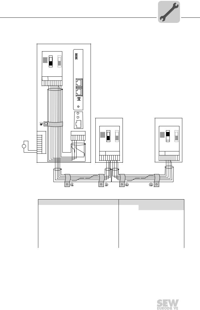
4.2.2Connecting system bus (SBus 1) between several MOVITRAC® B units
|
|
|
MOVITRAC® B |
|
|
|
|
|
|
||
|
|
|
|
|
DFE 32B |
|
|
|
|
|
|
|
|
|
S1 |
S2 |
RUN |
|
|
|
|
|
|
|
|
|
|
|
BUS |
|
|
|
|
|
|
|
|
|
ON |
|
FAULT |
|
|
|
|
|
|
|
|
|
|
|
|
|
|
|
|
|
|
|
|
|
OFF |
|
|
|
|
|
|
|
|
|
|
X44 |
|
|
|
|
|
|
|
|
|
|
|
FSC11B |
|
|
|
|
|
|
|
|
|
|
|
X45 |
X46 |
|
|
|
|
|
|
|
|
|
|
H L |
1 2 3 4 5 6 7 |
X30 |
|
|
|
|
|
|
|
|
|
|
|
|
|
|
|
|
|||
|
|
|
|
|
X32 |
|
|
|
|
|
|
|
|
|
|
|
Def IP |
|
|
|
|
|
|
|
|
|
|
|
AS |
|
|
|
|
|
|
|
|
|
|
|
0 |
1 |
|
|
|
|
|
|
|
|
|
|
PROFINET IO |
|
|
|
|
|
|
|
|
|
|
|
|
H1 |
|
|
|
|
|
|
|
|
|
|
|
H2 |
|
|
|
|
|
|
|
|
|
|
|
MOVITRAC® B |
MOVITRAC® B |
||||
|
|
|
|
|
X24 |
|
|
|
|
|
|
|
|
|
|
|
|
|
S1 |
S2 |
|
S1 |
S2 |
|
|
X12 |
|
|
X26 |
ON |
|
|
ON |
|
|
|
|
1 |
|
|
|
|
OFF |
|
|
OFF |
|
|
|
2 |
|
|
1 2 3 4 5 6 7 |
|
|
|
|||
|
|
3 |
|
|
|
X44 |
|
|
X44 |
|
|
+ |
|
4 |
|
|
|
|
|
|
|
|
|
|
5 |
|
|
|
|
|
|
|
|
|
|
DC 24 V = |
|
6 |
|
|
|
FSC11B |
|
FSC11B |
|
||
- |
24V IO |
7 |
|
|
|
|
|
||||
|
|
8 |
|
|
|
|
|
|
|
|
|
|
GND |
9 |
|
|
|
X45 |
X46 |
|
X45 |
X46 |
|
|
|
|
|
|
|
|
|||||
|
|
|
|
|
|
H L 1 2 3 4 5 6 7 |
H L 1 2 3 4 5 6 7 |
||||
|
|
|
|
|
|
|
|
|
|
61635AXX |
|
|
|
MOVITRAC® B |
|
|
|
|
DFE32B via UOH11B gateway housing |
||||
X46 |
Terminal assignment |
X26 |
Terminal assignment |
X46:1 |
SC11 (System bus high, incoming) |
X26:1 |
SC11 SBus +, CAN High |
|
|
|
|
X46:2 |
SC12 (System bus low, incoming) |
X26:2 |
SC12 SBus –, CAN Low |
|
|
|
|
X46:3 |
GND (System bus reference) |
X26:3 |
GND, CAN GND |
|
|
|
|
X46:4 |
SC21 (System bus high, outgoing) |
|
|
|
|
|
|
X46:5 |
SC22 (System bus low, outgoing) |
|
|
|
|
|
|
X46:6 |
GND (System bus reference) |
|
|
|
|
|
|
X46:7 |
DC 24 V |
X26:7 |
DC 24 V |
|
|
|
|
X12 |
Terminal assignment |
X12:8 |
DC+24 V input |
|
|
X12:9 |
GND reference potential for the binary inputs |
|
|
Phone: 800.894.0412 - Fax: 888.723.4773 - Web: www.clrwtr.com - Email: info@clrwtr.com
Manual – DFE32B PROFINET IO Fieldbus Interface |
|
|
15 |
|
|
|
|
|
|
|
|
|
|
|
|
4 |
Assembly and Installation Notes |
Installing the DFE32B option card in MOVIDRIVE® B |
Please note:
•Use a 2x2 core twisted pair and shielded copper cable (data transmission cable with
braided copper shield). Connect the shield flatly on both sides of the electronics shield clamp of MOVITRAC® B. Also connect the ends of the shield to GND. The ca-
ble must meet the following specifications:
–Cable cross section 0.25 mm2 (AWG18) ... 0,75 mm2 (AWG23)
–Line resistance 120 Ω at 1 MHz
–Capacitance per unit length ≤ 40 pF/m at 1 kHz Suitable cables are CAN bus or DeviceNet cables.
•The permitted total cable length depends on the baud rate setting of the SBus:
– |
250 kBaud: |
160 m |
– |
500 kBaud: |
80 m |
– |
1000 kBaud: |
40 m |
•Connect the system bus terminating resistor (S1 = ON) at the end of the system bus connection. Switch off the terminating resistor on the other units (S1 = OFF). The DFE32B gateway must always be connected either at the beginning or the end of the system bus connection and feature a permanently installed terminating resistor.
NOTES
•There must not be any potential displace ment between the units connected with the SBus. Take suitable measures to avoid a potential displacement, e.g. by connecting the unit ground connectors using a separate lead.
•Point-to-point wiring is not permitted.
Phone: 800.894.0412 - Fax: 888.723.4773 - Web: www.clrwtr.com - Email: info@clrwtr.com
16 |
|
|
Manual – DFE32B PROFINET IO Fieldbus Interface |
|
|
|
|
|
|
|
|
|
|
|
|
Assembly and Installation Notes |
4 |
Installing the DFE32B/UOH11B gateway |
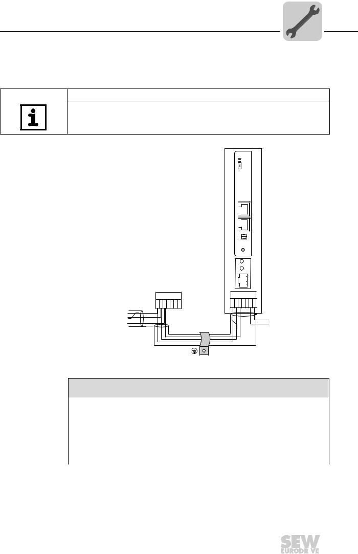
4.3Installing the DFE32B/UOH11B gateway
The following figure shows the connection of the DFE32B option via the UOH11B:X26 gateway housing.
NOTE
•Only SEW-EURODRIVE engineers are allowed to install or remove option cards
in/from the UOH11B gateway housing.
SC11 Systembus +, CAN high SC12 Systembus -, CAN low GND, CAN GND
UOH11B
DFE 32B


 RUN
RUN
 BUS
BUS
FAULT
X32 X30
Def IP 
AS 
0 1 PROFINET IO
H1
H2
X24
SEW Drive
X26
1 2 3 4 5 6 7
DC+24 V
GND
61636AXX
UOH11B gateway housing
X26 |
Terminal assignment |
X26:1 |
SC11 system bus +, CAN high |
|
|
X26:2 |
SC12 system bus, CAN low |
|
|
X26:3 |
GND, CAN GND |
|
|
X26:4 |
Reserved |
|
|
X26:5 |
Reserved |
|
|
X26:6 |
GND, CAN GND |
|
|
X26:7 |
DC 24 V |
|
|
The gateway housing has a power supply of DC 24 V that is connected to X26. Connect the system bus terminating resistor at the end of the system bus connection.
Phone: 800.894.0412 - Fax: 888.723.4773 - Web: www.clrwtr.com - Email: info@clrwtr.com
Manual – DFE32B PROFINET IO Fieldbus Interface |
|
|
17 |
|
|
|
|
|
|
|
|
|
|
|
|
4 |
Assembly and Installation Notes |
Connection and terminal description DFE32B option |
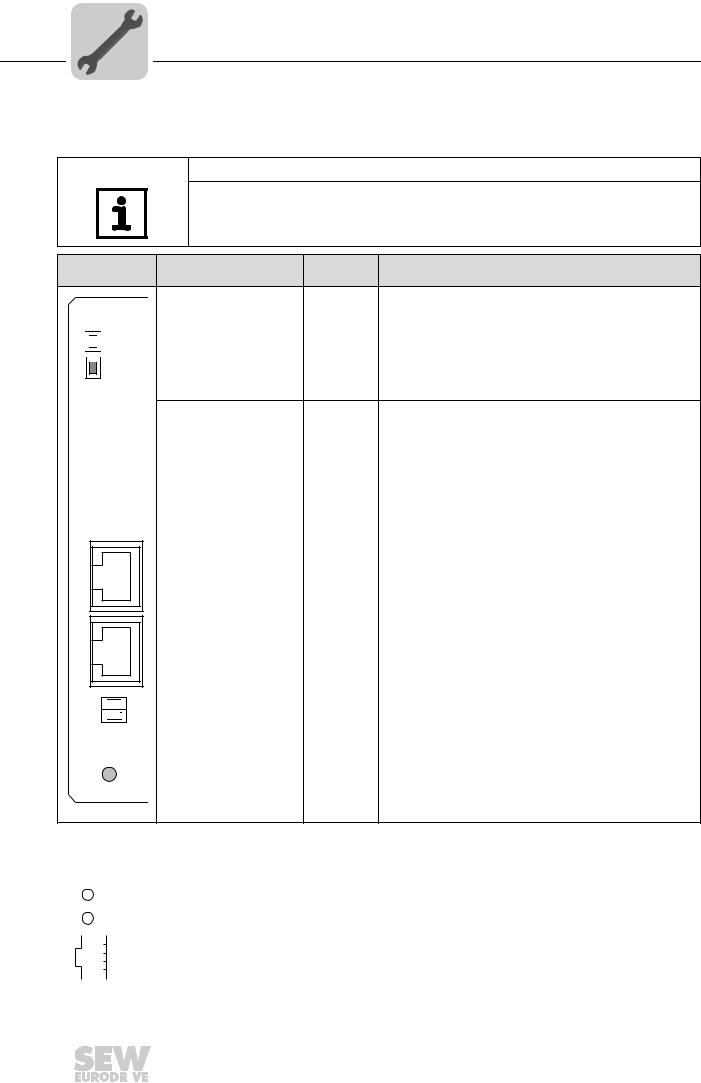
4.4Connection and terminal description DFE32B option
Part number |
DFE32B PROFINET IO fieldbus interface option: 1821 345 6 |
NOTES
•The "DFE32B PROFINET IO fieldbus interfac e " is only possible in conjunction with MOVIDRIVE® MDX61B, not with MDX60B.
•Plug the DFE32B option into the fieldbus slot.
Front view of
DFE32B
DFE 32B


 RUN
RUN
 BUS
BUS
FAULT
X30
X32
Def IP 
AS 
0 1 PROFINET IO
61630AXX
Description |
DIP |
Function |
|
switches |
|||
|
|
LED RUN (red/yel- |
Shows the current status of the DFE32B. |
|
low/green) |
Shows the status of the PROFINET IO connection. |
|
LED BUS FAULT (red/yel- |
||
|
||
low/green) |
|
X30: Ethernet connection |
|
|
|
LED Link (green) |
|
|
|
LED Activity (yellow) |
|
|
|
X32: Ethernet connection |
|
|
|
LED Link (green) |
|
|
|
LED Activity (yellow) |
|
|
|
|
|
|
|
DIP switches |
AS |
Auto setup for gateway operation |
|
|
DEF IP |
Resets the address parameters to the following default values: |
|
|
|
• |
IP address: 192.168.10.4 |
|
|
• |
Subnetwork mask: 255.255.255.0 |
|
|
• |
Gateway: 1.0.0.0 |
|
|
• PROFINET device name: PNETDeviceName_MACID |
|
Front view of MOVIT- |
Description |
Function |
||||
RAC® B, DFE32B and |
||||||
UOH11B |
|
|
||||
|
|
|
|
H1 |
LED H1 (red) |
System error (only for gateway functions) |
|
|
|
|
|||
|
|
|
|
H2 |
LED H2 (green) |
Reserved |
|
|
|
|
X24 |
X24 X terminal |
RS485 interface for diagnostics via PC and MOVITOOLS® |
|
|
|
|
|||
|
|
|
|
|
|
MotionStudio (only for MOVITRAC® B) |
|
|
|
|
58129axx |
|
|
|
|
|
|
|
|
|
|
|
|
|
|
|
|
Phone: 800.894.0412 - Fax: 888.723.4773 - Web: www.clrwtr.com - Email: info@clrwtr.com
18 |
|
|
Manual – DFE32B PROFINET IO Fieldbus Interface |
|
|
|
|
|
|
|
|
|
|
|
|
Assembly and Installation Notes |
4 |
Pin assignment |
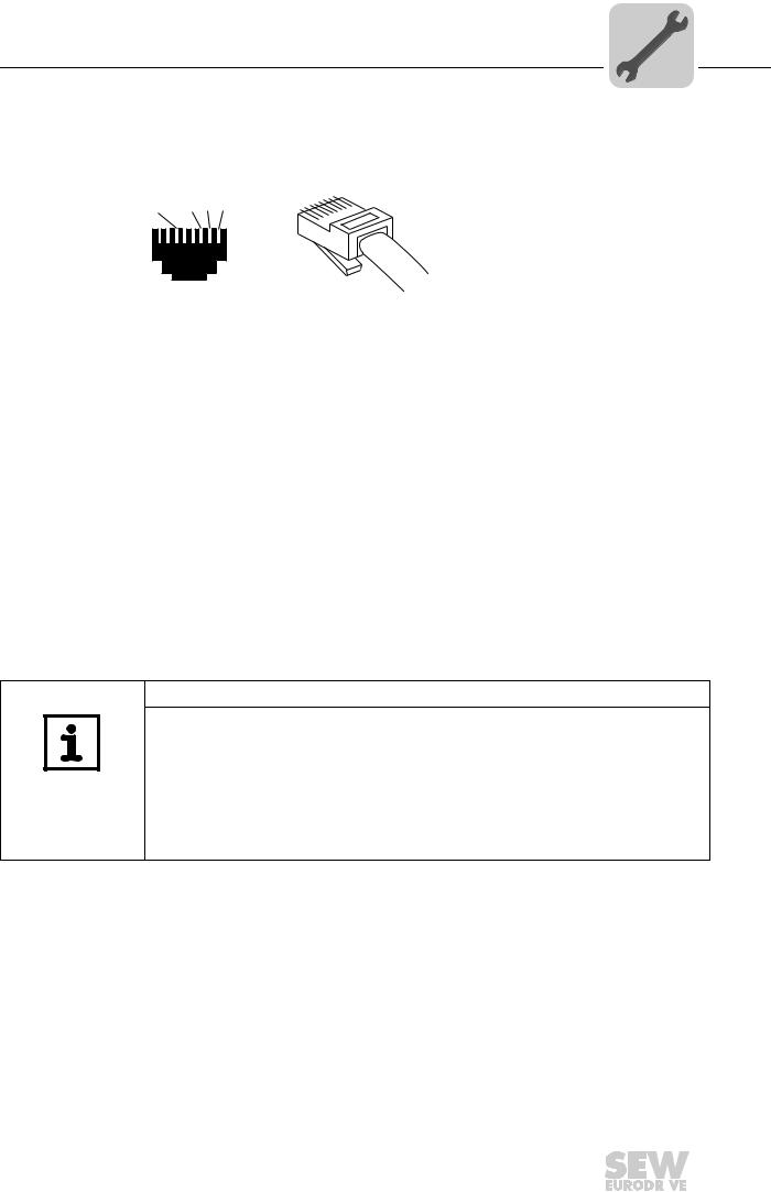
4.5Pin assignment
Use prefabricated, shielded RJ45 plug conectors compliant with IEC 11801, edition 2.0, category 5.
[6][3] [2] [1]
6
|
3 |
2 |
|
1 |
|
A B
54174AXX
Figure 1: Pin assignment of an RJ45 plug connector
A = Front view
B = View from back
[1]Pin 1 TX+ Transmit Plus
[2]Pin 2 TX– Transmit Minus
[3]Pin 3 RX+ Receive Plus
[6]Pin 6 RX– Receive Minus
Connection MOVIDRIVE® B / MOVITRAC® B / Ethernet
To connect the DFE32B, connect the Ethernet interface X30 or X32 (RJ45 connector) using a category 5, class D shielded twisted-pair cable in compliance with IEC 11801 edition 2.0. The integrated switch provides support for realizing a line topology.
NOTES
•According to IEC 802.3, the maximum cable length for 10 / 100 MBaud Ethernet (10BaseT / 100BaseT), e.g. between DFE32B and switch, is 100 m.
•VLAN tag prioritized Ethernet frames with the frame identification 8892 hex are used for the real-time data exchange with PROFINET IO. This requires switched networks. The switches must support prioritization. Hubs are not permitted. Data transmission takes place using the full duplex process with 100 MBit. Detailed information on cabling can be found in the 'PROFINET installation guideline' publication that was issued by the PROFINET user organization.
Phone: 800.894.0412 - Fax: 888.723.4773 - Web: www.clrwtr.com - Email: info@clrwtr.com
Manual – DFE32B PROFINET IO Fieldbus Interface |
|
|
19 |
|
|
|
|
|
|
|
|
|
|
|
|
4 |
Assembly and Installation Notes |
Shielding and routing bus cables |
4.6Shielding and routing bus cables
Only use shielded cables and connection elements that also meet the requirements of category 5, class 2 in compliance with IEC 11801 edition 2.0.
Correct shielding of the bus cable attenuates electrical interference that may occur in industrial environments. The following measures ensure the best possible shielding:
•Manually tighten the mounting screws on the connectors, modules, and equipotential bonding conductors.
•Use only connectors with a metal housing or a metallized housing.
•Connect the shielding in the connector over a wide surface area.
•Apply the shielding of the bus cable on both ends.
•Route signal and bus cables in separate cable ducts. Do not route them parallel to power cables (motor leads).
•Use metallic, grounded cable racks in industrial environments.
•Route the signal cable and the corresponding equipotential bonding close to each other using the shortest possible route.
•Avoid using plug connectors to extend bus cables.
•Route the bus cables closely along existing grounding surfaces.
STOP
In case of fluctuations in the ground potent ial, a compensating current may flow via the bilaterally connected shield that is also connected to the protective earth (PE). Make sure you supply adequate equipotential bonding according in accordance with relevant VDE regulations in such a case.
Phone: 800.894.0412 - Fax: 888.723.4773 - Web: www.clrwtr.com - Email: info@clrwtr.com
20 |
|
|
Manual – DFE32B PROFINET IO Fieldbus Interface |
|
|
|
|
|
|
|
|
|
|
|
|
Assembly and Installation Notes |
4 |
TCP / IP addressing and subnetworks |
4.7TCP / IP addressing and subnetworks
Introduction |
The settings for the address of the IP protocol are made using the following parameters: |
||||||||
|
• |
IP address |
|
|
|
|
|
|
|
|
• |
Subnetwork mask |
|
|
|
|
|
|
|
|
• |
Standard gateway |
|
|
|
|
|
|
|
|
The addressing mechanisms and subdivision of the IP networks into subnetworks are |
||||||||
|
explained in this chapter to help you set the parameters correctly. |
|
|
||||||
IP address |
The IP address is a 32 bit value that uniquely identifies a station in the network. An IP |
||||||||
|
address is represented by four decimal numbers separated by decimal points. |
||||||||
|
Example: 192.168.10.4 |
|
|
|
|
|
|||
|
Each decimal number stands for one byte (= 8 bits) of the address and can also be rep- |
||||||||
|
resented using binary code (→ following table). |
|
|
|
|||||
|
|
|
|
|
|
|
|
|
|
|
|
Byte 1 |
|
Byte 2 |
|
Byte 3 |
|
Byte 4 |
|
|
|
11000000 |
. |
10101000 |
. |
00001010 |
. |
00000100 |
|
|
|
|
|
|
|
|
|
|
|
|
The IP address comprises a network address and a station address ( → following table). |
||||||||
|
|
|
|
|
|
|
|
|
|
|
|
Network address |
|
|
Station address |
|
|
|
|
|
|
192.168.10 |
|
|
4 |
|
|
|
|
|
|
|
|
|
|
|
|
|
|
The part of the IP address that denotes the network and the part that identifies the station is determined by the network class and the subnetwork mask.
Station addresses cannot consist of only zeros or ones (binary) because they represent the network itself or a broadcast address.
Network classes The first byte of the IP address determines the network class and as such represents the division into network addresses and station addresses.
Value range |
Network class |
Complete network address |
Meaning |
|
Byte 1 |
(Example) |
|||
|
|
|||
0 ... 127 |
A |
10.1.22.3 |
10 = Network address |
|
|
|
|
1.22.3 = Station address |
|
128 ... 191 |
B |
172.16.52.4 |
172.16 = Network address |
|
|
|
|
52.4 = Station address |
|
|
|
|
|
|
192 ... 223 |
C |
192.168.10.4 |
192.168.10 = Network address |
|
|
|
|
4 = Station address |
|
|
|
|
|
This rough division is not sufficient for a number of networks. They also use an explicit, adjustable subnet mask.
Subnet mask |
A subnet mask is used to divide the networkclasses into even finer sections. Like the |
|||||||
|
IP address, the subnet mask is represented by four decimal numbers separated by dec- |
|||||||
|
imal points. Every decimal number stands for one byte. |
|
|
|
||||
|
Example: 255.255.255.128 |
|
|
|
|
|
||
|
Each decimal number stands for one byte (= 8 bits) of the subnet mask and can also be |
|||||||
|
represented using binary code (→ following table). |
|
|
|
||||
|
|
|
|
|
|
|
|
|
|
Byte 1 |
|
Byte 2 |
|
Byte 3 |
|
Byte 4 |
|
|
11111111 |
. |
11111111 |
. |
11111111 |
. |
10000000 |
|
|
|
|
|
|
|
|
|
|
If you compare the IP addresses with the subnet masks, you see that in the binary representation of the subnet mask all ones dete rmine the network address and all the zeros
Phone: 800.894.0412 - Fax: 888.723.4773 - Web: www.clrwtr.com - Email: info@clrwtr.com
Manual – DFE32B PROFINET IO Fieldbus Interface |
|
|
21 |
|
|
|
|
|
|
|
|
|
|
|
|

4 |
Assembly and Installation Notes |
TCP / IP addressing and subnetworks |
determine the station address (→ following table).
|
|
Byte 1 |
|
Byte 2 |
|
Byte 3 |
|
Byte 4 |
|
IP address |
decimal |
192 |
. |
168. |
. |
10 |
. |
128 |
|
|
|
|
|
|
|
|
|
||
Binary |
11000000 |
. |
10101000 |
. |
00001010 |
. |
10000000 |
||
|
|||||||||
|
|
|
|
|
|
|
|
|
|
Subnetwork mask |
decimal |
255 |
. |
255 |
. |
255 |
. |
128 |
|
|
|
|
|
|
|
|
|
||
Binary |
11111111 |
. |
11111111 |
. |
11111111 |
. |
10000000 |
||
|
|
|
|
|
|
|
|
|
The class C network with the address 192.168.10. is further subdivided into 255.255.255.128 using the subnetwork mask. Two networks are created with the ad-
dress 192.168.10.0 and 192.168.10.128.
The following station addresses are permitted in the two networks:
•192.168.10.1 ... 192.168.10.126
•192.168.10.129 ... 192.168.10.254
The network stations use a logical AND operation for the IP address and the subnetwork mask to determine whether there is a communication partner in the same network or in a different network. If the communication partner is in a different network, the standard gateway is addressed.
Standard gateway The standard gateway is also addressed via a 32-bit address. The 32-bit address is represented by four decimal numbers separated by decimal points.
Example: 192.168.10.1
The standard gateway establishes a connection to other networks. In this way, a network station that wants to address another station can use a logical AND operation with the IP address and the subnetwork mask to decide whether the desired station is located in the same network. If this is not the case, the station addresses the standard gateway (router), which must be part of the actual network. The standard gateway then takes on the job of transmitting the data packages.
Phone: 800.894.0412 - Fax: 888.723.4773 - Web: www.clrwtr.com - Email: info@clrwtr.com
22 |
|
|
Manual – DFE32B PROFINET IO Fieldbus Interface |
|
|
|
|
|
|
|
|
|
|
|
|

Assembly and Installation Notes |
4 |
Setting the IP address parameters via DCP |
4.8Setting the IP address parameters via DCP
Initial startup |
For PROFINET IO, the IP address parameters are determined via the "DCP" protocol |
|
|
(Discovery and Configuration Protocol). DCP operates with device names (Device |
|
|
Name). The device name uniquely identifies a PROFINET IO station in the network. It |
|
|
is identified with the PROFINET IO controller for the project planning of the station and |
|
|
also set using the project planning software on the PROFINET IO device. With the aid |
|
|
of the device name, the controller identifies the device during startup and transfers the |
|
|
corresponding IP address parameters. Settings directly on the slave are no longer re- |
|
|
quired. The basic procedure is described wit h SIMATIC STEP 7 as an example in chap- |
|
|
ter "Project Planning with PROFINET" →( section "Assigning the PROFINET device |
|
|
name"). |
|
Resetting the IP |
If you do not know the IP address parameters and cannot access the inverter using the |
|
address parame- |
serial interface or the DBG60B keypad, you can reset the IP address parameters to the |
|
ters |
default values using the DIP switch "Def IP". |
|
|
This action resets the DFE32B option to the following default values: |
|
|
• |
IP address: 192.168.10.4 |
|
• |
Subnetwork mask: 255.255.255.0 |
|
• |
Default gateway: 1.0.0.0 |
• PROFINET device name: PNETDeviceName_MACID
Proceed as follows to reset the IP address parameters to the default values:
•Switch off the 24 V DC supply voltage and the mains voltage.
•Set the DIP switch "Def IP" on the DFE32B option to "1."
•Switch the 24 V DC supply voltage and the mains voltage back on.
•Wait until the DFE32B option boots up. The "RUN" LED is green when the option is ready.
You can now access the inverter via the IPaddress 192.168.10.4. Proceed as follows to set new IP address parameters:
•Start a web browser and access the homepage of the DFE32B option or start MOVITOOLS® MotionStudio.
•Select the address parameters you want.
•Set the DIP switch "Def IP" on the DFE32B option to "0."
•The new address parameters are adopted after the device is switched off and switched on again.
Phone: 800.894.0412 - Fax: 888.723.4773 - Web: www.clrwtr.com - Email: info@clrwtr.com
Manual – DFE32B PROFINET IO Fieldbus Interface |
|
|
23 |
|
|
|
|
|
|
|
|
|
|
|
|

4 |
Assembly and Installation Notes |
Procedure after device replacement |
4.9Procedure after device replacement
4.9.1Device replacement MOVIDRIVE® B
If you insert the memory card of the replaced MOVIDRIVE ® B in the new MOVIDRIVE® B, the new device is recognized by the PROFINET IO controller without any additional measures.
NOTE
®
If you do not install the memory card of the replaced MOVIDRIVEB in the new MOVIDRIVE® B, you have to perform a complete startup of the inverter or you have to load the saved parameter set into the new MOVIDRIVE® B. Further, you have to set the PROFINET IO device name again using t he project planning software. Proceed as with an initial startup (→ chapter "Project Planning with PROFINET").
There are no measures required if only the DFE32B option is replaced.
4.9.2Device replacement MOVITRAC® B / gateway
•Only for device replacement MOVITRAC® B with fieldbus option: You have to load the saved parameter set into the new MOVITRAC ® B or you have to perform a complete startup of the inverter (→ operating instructions MOVITRAC® B).
•You have to set the PROFINET IO devic name again using the project planning software. Proceed as with an initial startup ( → chapter "Project Planning with PROFINET").
•Prior to the auto setup, check the parametersP884 SBus Baud Rate and P831 Reaction Fieldbus Timeout. The baud rate of the devices connected to the SBus has
to correspond to the baud rate of the gateway (DFE32B). Use the parameter tree of the gateway in MOVITOOLS® MotionStudio.
•Now activate the auto setup function. Se t the DIP switch "AS" on the DFE32B option to "1."
Phone: 800.894.0412 - Fax: 888.723.4773 - Web: www.clrwtr.com - Email: info@clrwtr.com
24 |
|
|
Manual – DFE32B PROFINET IO Fieldbus Interface |
|
|
|
|
|
|
|
|
|
|
|
|

Assembly and Installation Notes |
4 |
Operating display DFE32B option |
4.10Operating display DFE32B option
4.10.1 PROFINET-LEDs
There are two LEDs on the DFE32B option card that display the current status of the
DFE32B option and the PROFINET system.
DFE32B
RUN
BUS
FAULT
61629AXX
RUN LED |
The RUN LED indicates that the bus electronics are operating correctly |
|||
|
|
|
|
|
|
States of the |
Cause of error |
Remedy |
|
|
RUN LED |
|
|
|
|
Green |
• |
DFE32B hardware OK. |
– |
|
|
• |
Proper operation |
|
|
|
|
|
|
|
Off |
• DFE32B is not ready for opera- |
|
|
|
|
|
tion |
• Switch the unit on again. Consult SEW service |
|
Red |
• Error in the DFE32B hardware |
||
|
if the error occurs again. |
|||
|
|
|
|
|
|
Flashing |
|
|
|
|
green |
|
|
|
|
Flashing |
• Hardware of the DFE32B does |
• Switch the unit on again. Set default IP |
|
|
yellow |
addressparameter via DIP switch "DEF IP" . |
||
|
|
not boot up. |
||
|
|
|
Consult SEW service if the error occurs again. |
|
|
|
|
|
|
|
|
|
|
|
|
Yellow |
|
|
• Switch the unit on again. Consult SEW service |
|
|
|
|
if the error occurs again. |
BUS FAULT LED The BUS FAULT LED displays the status of the PROFINET.
Status of the |
Cause of error |
Remedy |
BUS FAULT LED |
|
|
Off |
• PROFINET IO device is currently |
- |
|
exchanging data with the PROFINET |
|
|
IO controller (Data Exchange). |
|
Flashing green |
• The flashing function in the PROFI- |
- |
Flashing |
NET IO controller project planning is |
|
green/red |
activated to visually localize the sta- |
|
|
tions. |
|
Red |
• Connection to the PROFINET IO |
• Check the PROFINET connection of |
|
controller has failed. |
the DFE32B option |
|
• PROFINET IO device does not |
• Check the PROFINET IO controller |
|
detect a link |
• Check the cabling of your PROFINET |
|
• Bus interruption |
network |
|
• PROFINET IO controller is not in |
|
|
operation |
|
|
|
|
Yellow |
• The STEP 7 hardware configuration |
• Switch the STEP 7 hardware configu- |
Flashing yellow |
contains a module that is not permit- |
ration to ONLINE and analyze the sta- |
|
ted. |
tus of the components of the slots in |
|
|
the PROFINET IO device. |
Phone: 800.894.0412 - Fax: 888.723.4773 - Web: www.clrwtr.com - Email: info@clrwtr.com
Manual – DFE32B PROFINET IO Fieldbus Interface |
|
|
25 |
|
|
|
|
|
|
|
|
|
|
|
|
4 |
Assembly and Installation Notes |
Operating display DFE32B option |
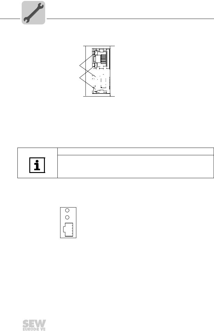
|
Link / Activity |
The two LEDs, Link (green) and Activity (yellow), integrated in the RJ45 plug connec- |
LED |
tors (X30, X32) display the status of the Ethernet connection. |
LED "Link"
LED "Activity"
X32 X30
61880AXX
LED / Status |
Meaning |
Link / Green |
There is an Ethernet connection. |
|
|
Link / Off |
There is no Ethernet connection. |
|
|
Activity / Yel- |
Data is currently being exchanged via Ethernet. |
low |
|
NOTES
•As the firmware of the DFE32B option card requires approximately 10 seconds for
initialization, the status "0" (inverter not ready) is displayed in the 7-segment display of MOVIDRIVE® during this time.
•The Run LED on the DFE32B option card lights up green.
4.10.2 Gateway LED
LEDs H1 and H2 indicate the communication status in gateway operation.
H1
H2
X24
58129axx
LED H1 Sys-fault (red) |
|
Only for gateway function |
|
Status |
State |
|
Description |
Red |
System error |
|
Gateway is not configured or one of the |
|
|
|
drives is inactive. |
|
|
|
|
Off |
SBus ok |
|
Gateway is configured correctly |
|
|
|
|
Flashes |
Bus scan |
|
Bus is being checked by the gateway |
|
|
|
|
Phone: 800.894.0412 - Fax: 888.723.4773 - Web: www.clrwtr.com - Email: info@clrwtr.com
26 |
|
|
Manual – DFE32B PROFINET IO Fieldbus Interface |
|
|
|
|
|
|
|
|
|
|
|
|

Assembly and Installation Notes
Operating display DFE32B option
NOTES
•LED H2 H2 (green) is currently reserved.
•X-terminal X24 is the RS-485 interface for diagnostics via PC and MOVITOOLS® MotionStudio.
Phone: 800.894.0412 - Fax: 888.723.4773 - Web: www.clrwtr.com - Email: info@clrwtr.com
Manual – DFE32B PROFINET IO Fieldbus Interface
4
27

5 |
|
Project Planning with PROFINET |
|
Project planning for the PROFINET IO controller |
|
|
|
|
|
|
|
5 Project Planning with PROFINET
This Chapter describes the project planning for the MOVIDRIVE® B and
MOVITRAC® B / gateway inverters with the DFE32B option. The following GSD file is used for the project planning of the DFE32B with MOVIDRIVE ® B or in MOVITRAC® B:
GSDML-V2.1-SEW-DFE-DFS-2Ports-jjjjmmtt.xml
This GSD file contains the unit description for the operation of the DFE32B in MOVIDRIVE® B or as fieldbus gateway for MOVITRAC® B.
5.1Project planning for the PROFINET IO controller
This chapter describes the project planning for MOVIDRIVE® B or MOVITRAC® B with PROFINET using the current GSD(ML) file. T he configuration is described using the example of the SIMATIC Manager project planning software with a SIMATIC CPU 315F 2 PN/DP.
Initializing the |
• Start STEP7 HWCONFIG and select the [Install new GSD file] menu item in the [Ex- |
GSD file |
tras] menu. |
|
• Select the file "GSDML-V2.1-SEW-DFE-DFS-2Ports-JJJJMMTT.xml" on the "Soft- |
|
ware ROM 7" CD as in the following dialog. "JJJJMMTT" [YYYYMMDD] represents |
|
the date of the file. You can navigate to t he required directory using the 'Browse' but- |
|
ton. Confirm your selection with [OK]. |
|
• You will find the SEW PROFINET IO DFE32B interface under [Other field devices] / |
|
[Drives] / [SEW] / [DFE/DFS(2Ports)]. |
NOTE
The latest GSD file version is alsoailableav for download on the SEW website in the "Software" section.
Phone: 800.894.0412 - Fax: 888.723.4773 - Web: www.clrwtr.com - Email: info@clrwtr.com
28 |
|
|
Manual – DFE32B PROFINET IO Fieldbus Interface |
|
|
|
|
|
|
|
|
|
|
|
|

Project Planning with PROFINET |
5 |
Project planning for the PROFINET IO controller |
5.1.1Assigning the PROFINET device name
The general procedure is described with SIMATIC STEP 7 as an example .
•In STEP 7 HWKONFIG, select [PLC] / [Ethernet] / [Edit Ethernet Node ...].
11727AEN
•Click on "Browse". You receive an overview of all PROFINET IO nodes that you can reach online with your project planning tool (→ following figure).
[2] |
[3] |
[4] |
[1]
62340AEN
•Choose the required station. The SEW node appears as "SEW-MDX61B+DFE32B" under Device type [3]. The device name [4]is set to 'PNETDeviceName' ex works and must be adapted to your system conditions. Several MDX61B units can be distinguished between by the MAC addresses [2] displayed. The MAC address [2] is attached to the DFE32B option. Use the [Flash] button [1] to enable the Status LED to flash green for the selected DFE32B in order to check your selection.
Phone: 800.894.0412 - Fax: 888.723.4773 - Web: www.clrwtr.com - Email: info@clrwtr.com
Manual – DFE32B PROFINET IO Fieldbus Interface |
|
|
29 |
|
|
|
|
|
|
|
|
|
|
|
|
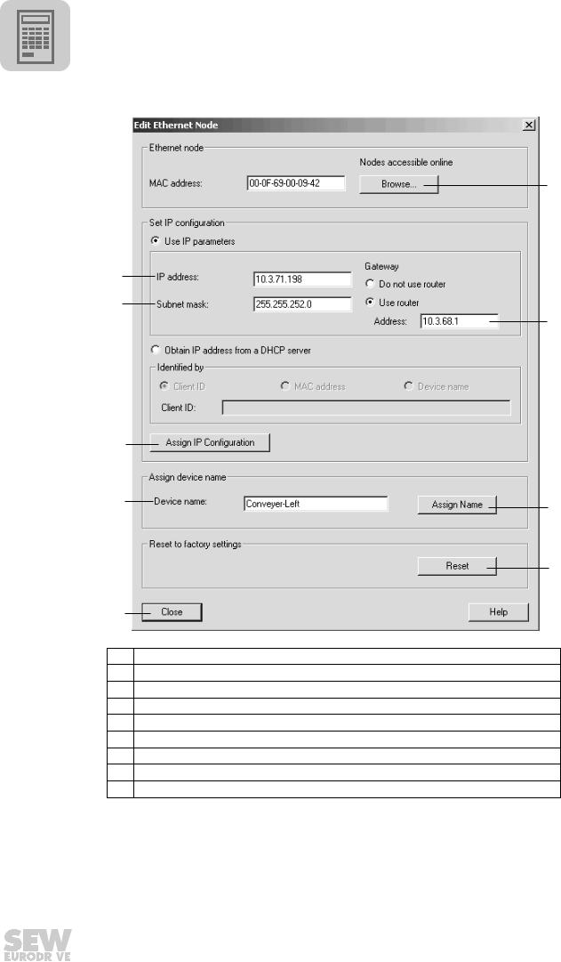
5 |
|
Project Planning with PROFINET |
|
Project planning for the PROFINET IO controller |
|
|
|
|
|
|
|
[6]
[5]
[4]
[7]
[3]
[2]
[8]
[9]
[1]
62330AEN
[1]"Close" button.
[2]"Device name" input field
[3]"Assign IP Configuration" button
[4]"Subnet mask" input field
[5]" IP address" input field
[6]"Browse" button
[7]" Router address" Input field
[8]"Assign name" button
[9]" Reset" button
•Enter the device name in the "Devicename" input field [2] and click the [Assign name] button [8]. The device name is now transferred to the station and saved there.
It can be up to 255 characters long.
•Specify an IP address [5] and a subnet mask [4] as well as a router address [7] if required. Click the [Assign IP Configuration] button [3].
Phone: 800.894.0412 - Fax: 888.723.4773 - Web: www.clrwtr.com - Email: info@clrwtr.com
30 |
|
|
Manual – DFE32B PROFINET IO Fieldbus Interface |
|
|
|
|
|
|
|
|
|
|
|
|
 Loading...