


MOVITRAC B
Drive Technology \ Drive Automation \ System Integration \ Services
MOVITRAC
®
B
Operating Instructions
Edition 05/2009
16810813 / EN

SEW-EURODRIVE—Driving the world

System Manual V3 – MOVITRAC® B
3
Contents
Contents
1 Important Information..................................... .................................................... 5
1.1 How to use the operating instructions......................................................... 5
1.2 Structure of the safety notes............................................................ .... ... ... . 6
1.3 Rights to claim under warranty ................................................................... 6
1.4 Exclusion of liability..................................................................................... 6
2 Safety Notes ........................................................................................................ 7
2.1 Preliminary information ............................................................................... 7
2.2 General.......................................................................................................7
2.3 Target group ............................................................................................... 8
2.4 Designated use......... .... ... ... ... .... ... .......................................................... ... . 8
2.5 Other applicable documentation................................................................. 9
2.6 Transport..................................................................................................... 9
2.7 Extended storage........................................................................................ 9
2.8 Installation/assembly................................................................................... 9
2.9 Electrical connection............................................................ ... .................. 10
2.10 Safe disconnection.... .... ... ... ... .... ... .......................................................... .. 10
2.11 Startup/operation ......................................................................................10
3 Unit Design ........................................................................................................ 11
3.1 Sizes 0XS / 0S / 0L................................................................................... 11
3.2 Sizes 1 / 2S / 2..........................................................................................12
3.3 Size 3........................................................................................................ 13
3.4 Sizes 4 / 5 .................................................................................................14
3.5 Unit designation / nameplate .................................................................... 15
4 Installation ......................................................................................................... 16
4.1 Recommended tools.................................................................................16
4.2 Installation notes....................................................................................... 16
4.3 Installing optional power components....................................................... 21
4.4 UL compliant installation...........................................................................26
4.5 Installation of loose items.......................................................................... 28
4.6 Requirements for installing cold plate (size 0 only)................................... 33
4.7 Deactivating EMC capacitors (size 0 only) ...............................................33
4.8 Wiring diagram.......................................................................................... 35
4.9 TF thermistor and TH bimetallic switch..................................................... 36
4.10 Connecting braking resistor BW..-P / BW..-T / BW.. to X3 / X2 ................ 36
4.11 Connecting brake rectifiers ....................................................................... 37
4.12 Installing FSC11B / FIO11B / FIO21B ...................................................... 38
4.13 Installing the MBG11A speed control module...........................................43
Phone: 800.894.0412 - Fax: 888.723.4773 - Web: www.clrwtr.com - Email: info@clrwtr.com

4
System Manual V3 – MOVITRAC® B
Contents
5 Startup................................................................................................................ 44
5.1 Brief description of the startup process..................................................... 44
5.2 General startup instructions.......... ...... .... ... ... ... ... .... ... ... ... .... ... ... ... ... .... ..... 45
5.3 Preliminary work and resources................................................................ 46
5.4 Optional keypad FBG11B ......................................................................... 47
5.5 Basic operation of the FBG11B keypad.................................................... 48
5.6 Manual operation with FBG11B speed control module............................ 50
5.7 External setpoint selection........................................................................ 51
5.8 Startup using the FBG11B keypad ........................................................... 52
5.9 Startup with PC and MOVITOOLS
®
MotionStudio....................................55
5.10 Startup of explosion-proof AC asynchronous motors of category 2
(94/9/EC)................................................................................................... 56
5.11 Starting the motor ..................................................................................... 57
5.12 Parameter list.......................................... ... ... ... ... .... ... ............................... 61
6 Operation ........................................................................................................... 72
6.1 Data backup..............................................................................................72
6.2 Return codes (r-19 – r-38) ........................................................................ 73
6.3 Status displays.......................................................................................... 74
6.4 Unit status codes ...................................................................................... 75
7 Service / List of Faults...................................................................................... 76
7.1 Unit information......................................................................................... 76
7.2 List of faults (F-00 – F-113)....................................................................... 78
7.3 SEW electronics service ........................................................................... 81
7.4 Extended storage...................................................................................... 82
8 Technical Data................................................................................................... 83
8.1 CE marking, UL approval and C-Tick ....................................................... 83
8.2 General technical data........... .... ... ... ... .... ... ... ... ... .... ... ... ... ....... ... ... ... .... ... .. 84
8.3 MOVITRAC
®
B electronics data ............................................................... 86
8.4 Technical data of MOVITRAC
®
B.............................................................88
8.5 Front option FBG11B keypad ................................................................. 107
8.6 FSC11B communication module ........ ....... ... ... ... .... ... ... ... .... ... ... ... ... .... ... 108
8.7 FIO11B analog module........................................................................... 109
8.8 FIO21B digital module ............................................................................110
Index................................................................................................................. 111
Phone: 800.894.0412 - Fax: 888.723.4773 - Web: www.clrwtr.com - Email: info@clrwtr.com

Operating Instructions V3 – MOVITRAC® B
5
1
How to use the operating instructions
Important Information
1 Important Information
1.1 How to use the operating instructions
The operating instructions are an integral part of the product and contain important
information for operation and service. The operating instructions are written for all
employees who assemble, install, startup, and service this product.
The operating instructions must be legible and accessible at all times. Make sure that
staff responsible for the plant and its operation, as well as persons who work indepen-
dently on the unit, have read the operating instructions carefully and understood them.
If you are unclear about any of the information in this documentation, or if you require
further information, contact SEW-EURODRIVE.
1.1.1 Text Conventions
• Texts in softwa re user interfaces (menu item s, buttons, etc.) in square bracket s, e.g.:
"Click the [Start] button."
• Parameter names are written in italics, e.g.: "Write down the values of variables H509
ACT.POS.ABS.".
• The display of the FBG11B keypad is indicated by a font with fixed character width,
e.g.: "The display shows Stop."
Phone: 800.894.0412 - Fax: 888.723.4773 - Web: www.clrwtr.com - Email: info@clrwtr.com
6
Operating Instructions V3 – MOVITRAC® B
1
Structure of the safety notes
Important Information
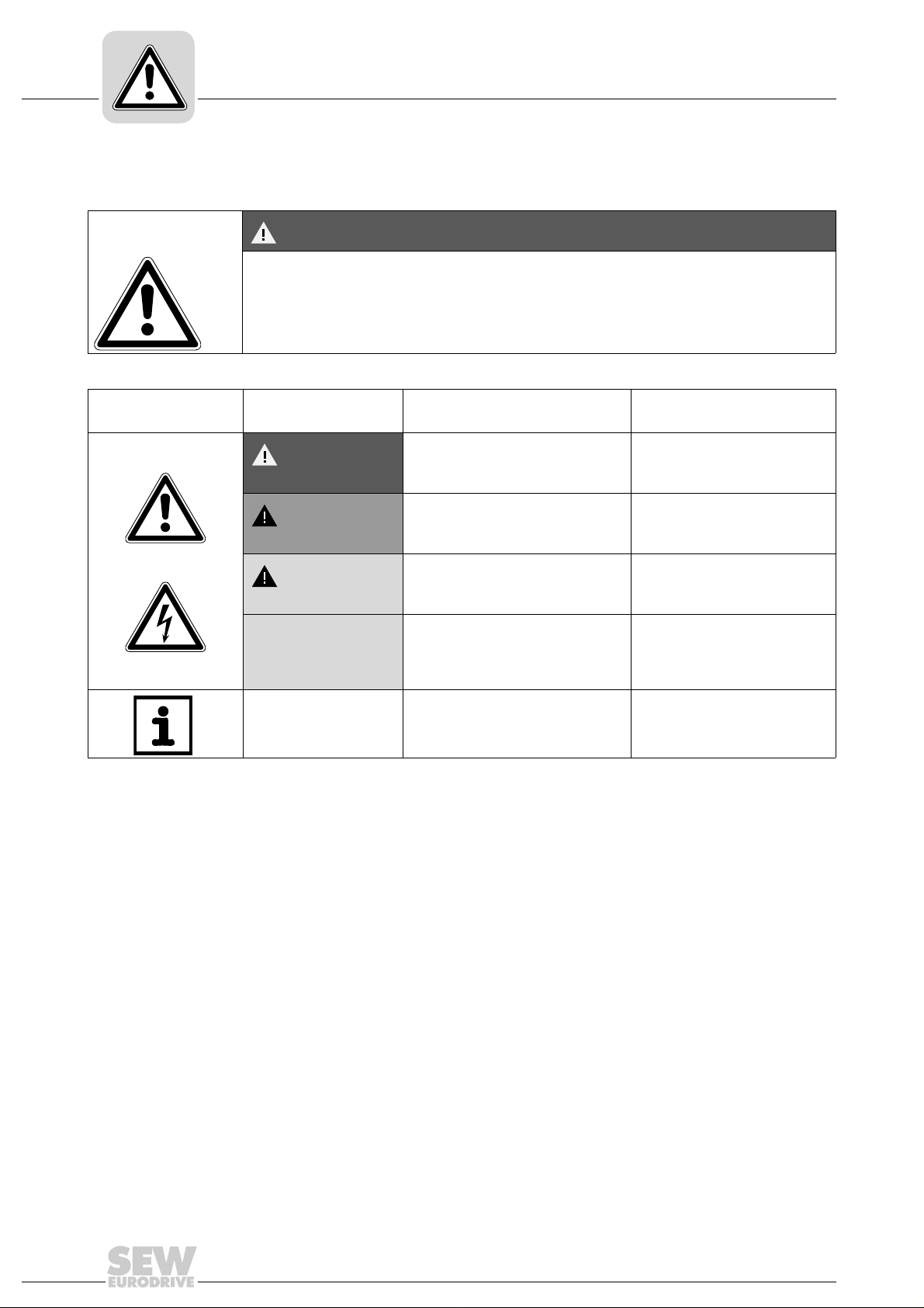
1.2 Structure of the safety notes
The safety notes in these operating instructions are designed as follows:
1.3 Rights to claim under warranty
A requirement of fault-free operation and fulfillment of any rights to claim under limited
warranty is that you adhere to the information in the operating instructions. Therefore,
read the operating instructions before you start working with the unit.
1.4 Exclusion of liability
You must comply with the information contained in these operating instructions to
ensure safe operation of MOVITRAC
®
B frequency inverters and to achieve the
specified product characteristics and performance requirements. SEW-EURODRIVE
does not assume liability for injury to persons or damage to equipment or property
resulting from non-observance of these operat ing instructions. In such cases, any liabil-
ity for defects is excluded.
Pictogram
SIGNAL WORD
Type and source of danger.
Possible consequence(s) if the safety notes are disregarded.
• Measure(s) to prevent the danger.
Pictogram Signal word Meaning Consequences if
disregarded
Example:
General danger
Specific danger, such
as electric shock
DANGER Imminent danger Severe or fatal injuries
WARNING Possible dangerous situation Severe or fatal injuries
CAUTION Possible dangerous situation Minor injuries
NOTICE Possible damage to property Damage to the drive system or
its environment
TIP Useful information or tip.
Simplifies the handling of the drive
system.
Phone: 800.894.0412 - Fax: 888.723.4773 - Web: www.clrwtr.com - Email: info@clrwtr.com
Operating Instructions V3 – MOVITRAC® B
7
2
Preliminary information
Safety Notes
2 Safety Notes
The following basic safety notes must be read carefully to prevent injury to persons a nd
damage to property. The operator must ensure that the basic safety notes a re read and
observed. Make sure that persons responsible for the plant and its operation, as well as
persons who work independently on the unit, have read through the operating instruc-
tions carefully and understood them. If you are unclear about any of the information in
this documentation, or if you require further information, please contact SEW-
EURODRIVE.
2.1 Preliminary information
The following safety notes predomin antly refer to the use of frequency inverters. Addi-
tionally, when using drives with motors or gearmotors, observe the corresponding safety
notes in the respective operating instructions.
Also observe the supplementary safety notes in the individual sections of this publica-
tion.
2.2 General
Removing covers without authorization, improper use as we ll as incorrect in stallation or
operation may result in severe injuries to persons or damage to property.
This document includes further information.
DANGER
During operation, frequency inverters can have live, bare parts according to their
degree of protection.
Severe or fatal injuries.
• All work related to transportation, storage, setup/mounting, connection, startup,
maintenance and repair may only be carried out by qualified personnel, in strict
observation of:
– The relevant detailed operating instructions
– The warning and safety signs on the motor/gearmotor
– All other project planning documents, operating instructions and wiring
diagrams related to the drive
– The specific regulations and requirements for the system
– The national/regional regulations governing safety and the prevention of
accidents
• Never install damaged products.
• Immediately report any damages to the shipping company.
Phone: 800.894.0412 - Fax: 888.723.4773 - Web: www.clrwtr.com - Email: info@clrwtr.com

8
Operating Instructions V3 – MOVITRAC® B
2
Target group
Safety Notes
2.3 Target group
Any mechanical work may only be performed by adequately qualified person nel. Quali-
fied personnel in this context are persons who are familiar with the setup, mechanical
installation, trouble shooting and maintenance for this product. Further, they are quali-
fied as follows:
• Training in mechanical engineering, e.g. as a mechanic or mechatronics technician
(final examinations must have been passed).
• They are familiar with these operating instructions.
Any electronic work may only be per form ed by adequately qualified electricians. Quali-
fied electricians in this context are persons who are familiar with the electronic installa-
tion, startup, trouble shooting and maintenance for this product. Further, they are qual-
ified as follows:
• Training in electrical engineering, e.g. as an electrician or me chatronics technician
(final examinations must have been passed).
• They are familiar with these operating instructions.
All work in further areas of transportation, storage, operation and waste disposal may be
carried out only by persons who are trained appropriately.
2.4 Designated use
Frequency inverters are components for controlling asynchronous AC motors.
Frequency inverters are components intended for installation in electrical systems or
machines. Never connect capacitive loads. Operation with capacitive loads results in
over voltages and may destroy the unit.
The following standards apply, if the frequency inverters a re mar k eted in th e EU/EF TA:
• In case of installation in machines, startup of the drive inverters (meaning the start of
proper use) is prohibited until it is determined that the machine meets the
requirements stipulated in the EC Directive 98/37/EC (m achine directive); observe
EN 60204.
• Startup (i.e. the start of designated use) is only permitted under observance of the
EMC (2004/108/EC) directive.
• The frequency inverters comply with the requirements of the Low Voltage Directive
2006/95/EC. The harmonized standards of the EN 61800-5-1/DIN VDE T105 series
in connection with EN 60439-1/VDE 0660 part 500 and EN 60146/VDE 0558 are
applied to these frequency inverters.
Observe the technical data and the connection requirements specified o n the nameplate
and the operating instructions.
2.4.1 Safety functions
Frequency inverters from SEW-EURODRIVE must not perform any safety functions
unless the inverters are subordinate to other safety systems.
Use higher-level safety systems to ensure protection of equipment and personnel.
Phone: 800.894.0412 - Fax: 888.723.4773 - Web: www.clrwtr.com - Email: info@clrwtr.com

Operating Instructions V3 – MOVITRAC® B
9
2
Other applicable documentation
Safety Notes
2.5 Other applicable documentation
When using the "Safe stop" function, you must observe the following publications:
•MOVITRAC
®
B / Safe Disconnection – Conditions
•MOVITRAC
®
B / Safe Disconnection – Applications
These publications are available via Documentation\Software\CAD on the SEW-
EURODRIVE homepage.
2.6 Transport
Immediately upon receipt, inspect the shipment for any da mage that may have occurred
during transportation. Inform the shipping company immediately in the even t of damage.
It may be necessary to preclude startup. Observe the climate conditions according to
chapter "General technical data".
2.7 Extended storage
Observe the notes in section "Extended storage".
2.8 Installation/assembly
The units must be installed and cooled according to the regulations and specifications
in this documentation.
Protect the frequency inverters from excessive strain. Do not twist any components and
do not modify the insulation spaces. Do not touch any electronic components or
contacts.
Frequency inverters contain components that can easily be damaged by electrostatic
energy and improper handling. Electric components m ust not be mechanically damaged
or destroyed.
The following applications are prohibited unless the unit is explicitly designed for such
use:
• Use in potentially explosive atmospheres.
• Use in areas exposed to harmful oils, acids, gases, vapors, dust, radiation, etc.
(frequency inverter may only be operated in climate class 3K3 to EN 60721-3-3)
• Use in non-stationary applications which are subject to mechanical vibration and
impact loads in excess of the requirements in EN 61800-5-1.
Phone: 800.894.0412 - Fax: 888.723.4773 - Web: www.clrwtr.com - Email: info@clrwtr.com

10
Operating Instructions V3 – MOVITRAC® B
2
Electrical connection
Safety Notes
2.9 Electrical connection
Observe the applicable national accident prevention guidelines when working on live
frequency inverters (e.g. BGV A3 for Germany).
During installation, observe the specifications regarding cable cross sections, fusing and
protective conductor connection. This publication contains additional information.
In this documentation, you will find notes on EMC compliant installation, such as
shielding, grounding, arrangement of filters and routing of lines. The manufacturer of the
system or machine is responsible for maintaining the limits established by EMC legisla-
tion.
Protective measures and protection devices must comply with the regulations in force
(e.g. EN 60204 or EN 61800-5-1).
Ground the unit.
2.10 Safe disconnection
The unit meets all requirements for safe disconnection of power and electronic
connections in accordance with EN 61800-5-1. All connected circuits must also satisfy
the requirements for safe disconnection.
2.11 Startup/operation
Systems with integrated frequency inverters must be equipped with additional monitor-
ing and protection devices, as applicable, according to the relevant safety guidelines
and regulations, such as legislation governing technical equipment, accident prevention
regulations, etc.
Do not touch live components or power connections until 10 minutes after disconnecting
the frequency inverters from the supply voltage because there may still be some
charged capacitors. Observe the corresponding labels on the frequency inverter.
Keep all covers and doors closed during operation.
The fact that the status LED and other display elements are no longer illuminated does
not indicate that the unit has been disconnected from the mains and no longer carries
any voltage.
Mechanical blocking or safety functions inside the unit may result in the motor coming
to a standstill. Eliminating the cause of the problem or performing a reset may result in
the drive re-starting automatically. If, for safety reasons, this is not permitted for the
driven machine, disconnect the unit from the supply system before correcting th e error.
Phone: 800.894.0412 - Fax: 888.723.4773 - Web: www.clrwtr.com - Email: info@clrwtr.com
Operating Instructions V3 – MOVITRAC® B
11
3
Sizes 0XS / 0S / 0L
Unit Design
3 Unit Design
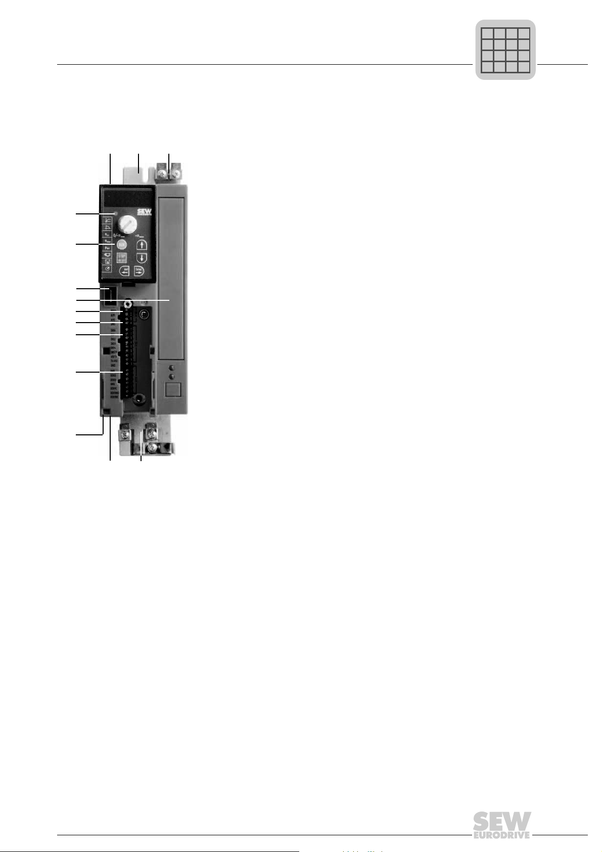
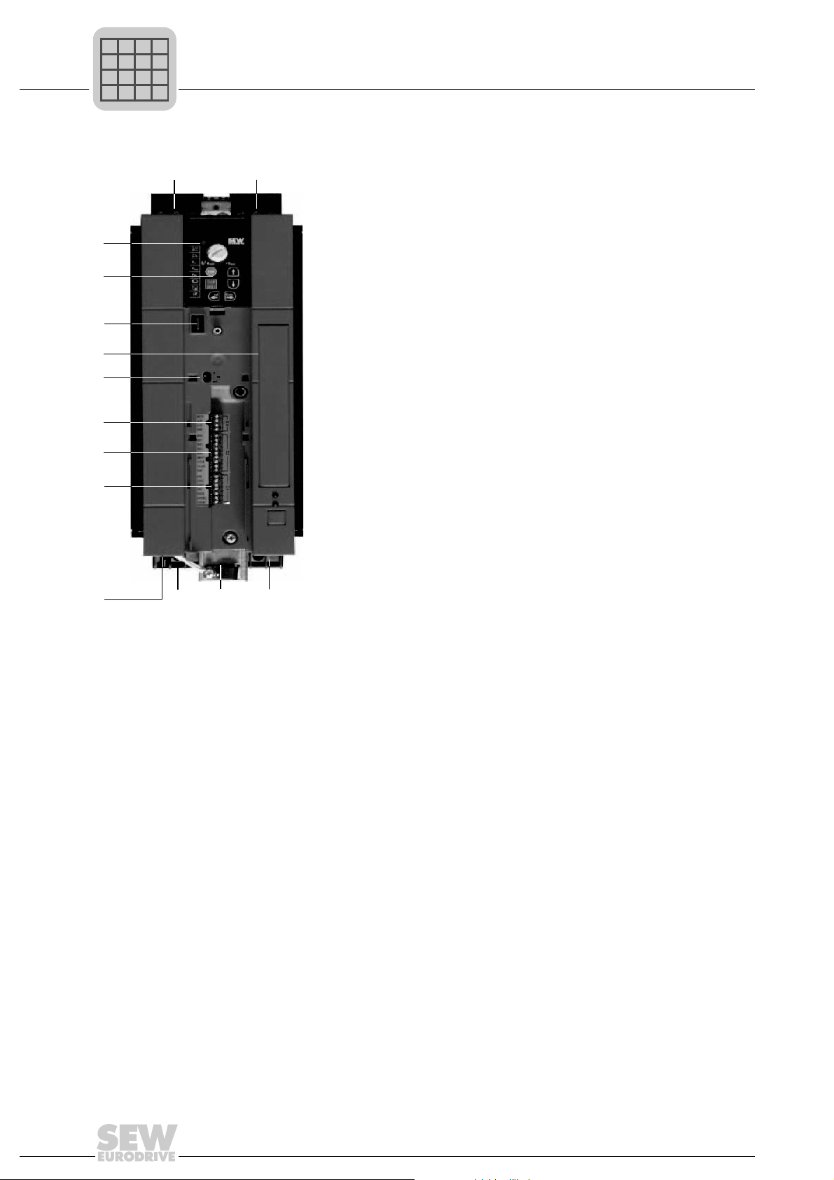
3.1 Sizes 0XS / 0S / 0L
[1] X1: Power supply connection:
3-phase: L1 / L2 / L3
1-phase: L / N
[2] Fixing strap
[3] PE connection
[4] Shield plate for motor cable, fixing strap underneath
[5] X2: Motor connection U / V / W / Brake connection +R / –R
[6] X17: Safety contact for safe stop (only MC07B...-S0: sizes 0S / 0L, 400 / 500 V)
[7] X13: Binary outputs
[8] X12: Binary inputs
[9] X10: Analog input
[10] Switch S11 for V-mA toggle an a l og in pu t
(in sizes 0XS and 0S behind removable connector)
[1 1] Option card slot (cannot be retrofitted / not for BG0XS)
[12] Connection for optional communication / analog module
[13] Optional keypad, inserted
[14] Status LED (visible without optional keypad)
[3]
[4][5]
[12]
[1]
[7]
[8]
[10]
[9]
[11]
[13]
[14]
[6]
[2]
P
i
f
kVA
Hz
n
P
i
f
kVA
Hz
n
Phone: 800.894.0412 - Fax: 888.723.4773 - Web: www.clrwtr.com - Email: info@clrwtr.com
12
Operating Instructions V3 – MOVITRAC® B
3
Sizes 1 / 2S / 2
Unit Design
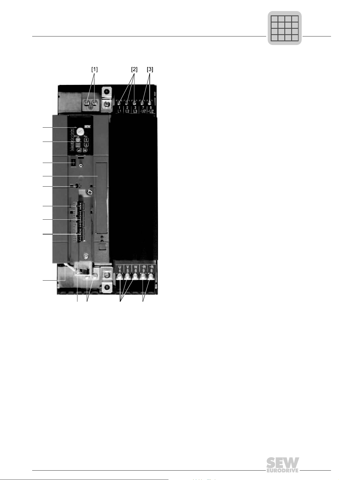
3.2 Sizes 1 / 2S / 2
[1] X1: Power supply connection 3-phase: L1 / L2 / L3 / PE screw
[2] X4: DC link connection –U
Z
/ +U
Z
[3] X3: Braking resistor connection R+ / R– / PE
[4] Electronics shield clamp
[5] X2: Motor connection U / V / W / PE screw
[6] X17: Safety contact for safe stop (only 400 / 500 V)
[7] X13: Binary outputs
[8] X12: Binary inputs
[9] X10: Analog input
[10] Switch S11 for V-mA toggle an a l og in pu t
[1 1] Option card slot
[12] Connection for optional communication / analog module
[13] Optional keypad, inserted
[14] Status LED (visible without optional keypad)
[7]
[8]
[9]
[10]
[11]
[12]
[13]
[14]
[4]
[2][1]
[3][5][6]
P
i
f
kVA
Hz
n
P
i
f
kVA
Hz
n
Phone: 800.894.0412 - Fax: 888.723.4773 - Web: www.clrwtr.com - Email: info@clrwtr.com
Operating Instructions V3 – MOVITRAC® B
13
3
Size 3
Unit Design
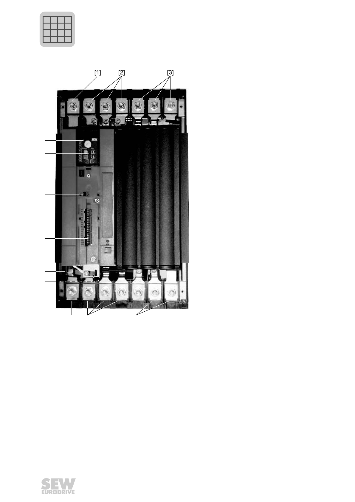
3.3 Size 3
[1] X2: PE connection
[2] X1: Power supply connection 3-phase: 1/L1 / 2/L2 / 3/L3
[3] X4: DC link connection –U
Z
/ +U
Z
[4] X3: Braking resistor connection R+ (8) / R– (9) and PE connection
[5] X2: Motor connection U (4) / V (5) / W (6)
[6] X2: PE connection
[7] Electronics shield clamp
[8] X17: Safety contact for safe stop (only 400 / 500 V)
[9] X13: Binary outputs
[10] X12: Binary inputs
[1 1] X10: Analog input
[12] Switch S11 for V-mA toggle an a l og in pu t
[13] Option card slot
[14] Connection for optional communication / analog module
[15] Optional keypad, inserted
[16] Status LED (visible without optional keypad)
[9]
[10]
[11]
[12]
[13]
[14]
[15]
[16]
[8]
[7]
[4][5][6]
P
i
f
kVA
Hz
n
P
i
f
kVA
Hz
n
Phone: 800.894.0412 - Fax: 888.723.4773 - Web: www.clrwtr.com - Email: info@clrwtr.com
14
Operating Instructions V3 – MOVITRAC® B
3
Sizes 4 / 5
Unit Design
3.4 Sizes 4 / 5
[1] X2: PE connection
[2] X1: Power supply connection 3-phase: 1/L1 / 2/L2 / 3/L3
[3] X4: DC link connection –U
Z
/ +U
Z
and PE connection
[4] X3: Braking resistor connection R+ (8) / R– (9) and PE connection
[5] X2: Motor connection U (4) / V (5) / W (6)
[6] X2: PE connection
[7] Electronics shield clamp
[8] X17: Safety contact for safe stop (only 400 / 500 V)
[9] X13: Binary outputs
[10] X12: Binary inputs
[1 1] X10: Analog input
[12] Switch S11 for V-mA toggle an a l og in pu t
[13] Option card slot
[14] Connection for optional communication / analog module
[15] Optional keypad, inserted
[16] Status LED (visible without optional keypad)
[6] [4][5]
[9]
[10]
[11]
[12]
[13]
[14]
[15]
[16]
[8]
[7]
P
i
f
kVA
Hz
n
P
i
f
kVA
Hz
n
Phone: 800.894.0412 - Fax: 888.723.4773 - Web: www.clrwtr.com - Email: info@clrwtr.com
Operating Instructions V3 – MOVITRAC® B
15
3
Unit designation / nameplate
Unit Design
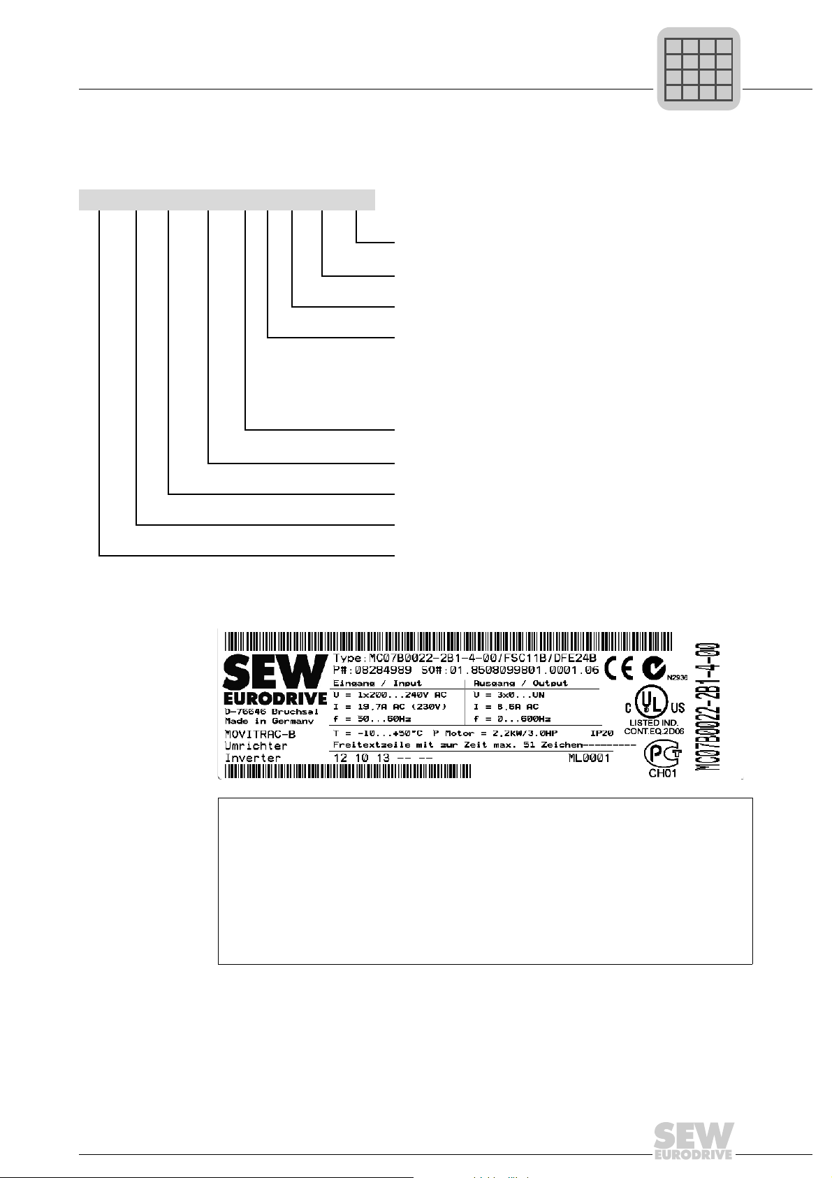
3.5 Unit designation / nameplate
MC 07 B 0022- 2 B 1- 4- 00
Design
00 = Standard
S0 = Safe stop
Quadrants 4 = 4Q (with brake chopper)
Connection type 3 = 3-phase / 1 = 1-phase
Radio interference suppression
0 = No radio interference
suppression
A = Radio interference
suppression C2
B = Radio interference
suppression C1
Supply voltage
2 = AC 200 – 240 V
5 = AC 380 – 500 V
Recommended motor power 0022 = 2.2 kW
Version B
Series and generation
MOVITRAC
®
type
Input U Rated mains voltage
I Rated mains current, 100 % operation
f Rated mains frequency
Output U Output voltage 100 % operation
I Rated output current 100 % operation
f Output frequency
T Ambient temperature
P motor Recommended motor power 100 % operation
The unit status for communication with SEW-EURODRIVE is indicated over the bar code at the bottom. The
unit status documents the hardware and software states of the unit.
P
i
f
kVA
Hz
n
P
i
f
kVA
Hz
n
Phone: 800.894.0412 - Fax: 888.723.4773 - Web: www.clrwtr.com - Email: info@clrwtr.com

16
Operating Instructions V3 – MOVITRAC® B
4
Recommended tools
Installation
4 Installation
4.1 Recommended tools
• Use a screwdriver with a 2.5 mm wide blade for connecting the electronics terminal
strip X10 / X12 / X13.
4.2 Installation notes
4.2.1 Mounting the front options
Attach the front options as follows:
• Inserting the FBG11A [A] keypad:
1. Insert the FBG11B keypad [A] on top of the housing [A1].
2. Press the socket on the keypad onto the connector in the unit [A2].
• Inserting the FSC11B communication module or the FIO11B analog module [B]:
1. For size 0, mount the spacer bolt [B1] when using the FSC11B communication
module or FIO11B analog module [B].
2. Insert the FSC11B communication module and the FIO11B analog module [B] at
the bottom of the housing [B2].
3. Press the socket on the front option onto the connector in the unit [B3].
4. Secure the front option using the screw on the unit [B4].
• Mounting the cover [C]:
1. Position the cover [C] on the unit approximately 5 mm away from its final position
[C1].
2. Move the cover upwards [C2].
[A1]
[B2]
[C1]
[A2]
[B3]
[C2]
[A]
[B]
[C]
[B1]
[B4]
P
i
f
kVA
Hz
n
P
i
f
kVA
Hz
n
Phone: 800.894.0412 - Fax: 888.723.4773 - Web: www.clrwtr.com - Email: info@clrwtr.com
Operating Instructions V3 – MOVITRAC® B
17
4
Installation notes
Installation
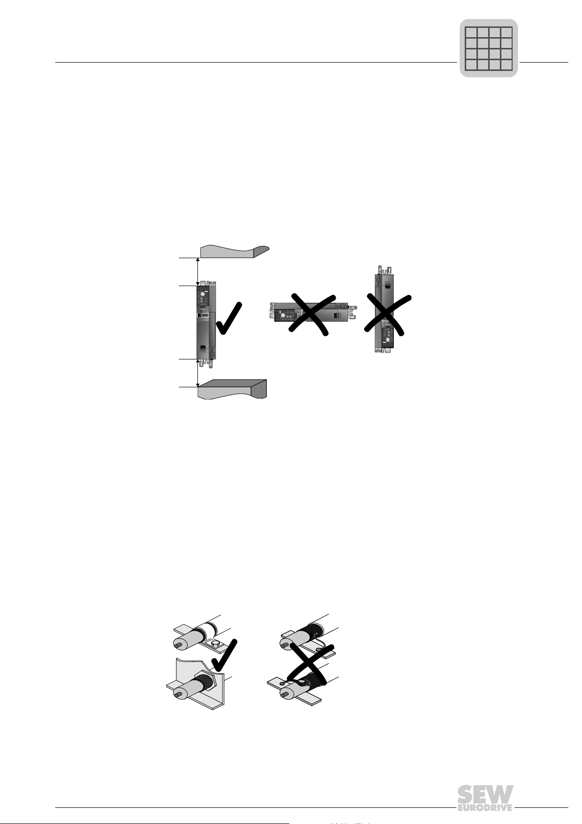
4.2.2 Minimum clearance and mounting position
• Leave 100 mm (3.94 in) clearance at the top and bottom of the housing for optimum
cooling. There is no need for clearance at the sides. You can line up the units directly
next to one another.
• It is important that air circulation is not impeded by cables and other installation
material. Prevent the heated exhaust air from other unit s from blowing onto this unit.
• Install the units vertically only. You must not install them horizontally, tilted or upside
down.
• Proper heat dissipation of the rear side of the heat sink improves the thermal
utilization of the unit.
4.2.3 Separate cable ducts
• Route power cables and electronics cables in separate cable ducts.
4.2.4 EMC-compliant installation
• Shield all cables except for the power supply cable. For the motor cable, you can use
the HD.. option (output choke) instead of the shielding to meet the interference
emission limit values .
• When using shielded motor cables, e.g. prefabricated motor cables from SEW-
EURODRIVE, you must keep the unshielded conductors between the shield and
connection terminal of the inverter as short as possible.
• Connect the shield by the shortest possible route a nd make sur e it is gr ou nde d over
a wide area at both ends. If using double-shielded cables, ground the outer shield on
the inverter end and the inner shield at the other end.
100 mm
(3.94 in)
100 mm
(3.94 in)
P
i
f
kVA
Hz
n
P
i
f
kVA
Hz
n
Phone: 800.894.0412 - Fax: 888.723.4773 - Web: www.clrwtr.com - Email: info@clrwtr.com

18
Operating Instructions V3 – MOVITRAC® B
4
Installation notes
Installation
• You can also use earthed sheet-metal ducts or metal pipes to shield the cables.
Install the power and control cables separately.
• Provide high frequency compatible grounding for the inverter and all additional units
(wide area metal-on-metal contact between the unit housing and ground, e.g.
unpainted control cabinet mounting panel).
4.2.5 Operation on IT systems
• SEW recommends using earth-leakage monitors with a pulse code measuring
process in voltage supply systems with a non-earthed star point (IT systems). Use of
such devices prevents the earth-leakage monitor mis-tripping due to the earth
capacitance of the inverter.
• For size 0, SEW recommends deactivating the interference suppressor filter using
the enclosed insulation discs (see Deactivating EMC capacitors (size 0 only)).
4.2.6 Utilization category of contactors
• Use only contactors in utilization category AC-3 (EN 60947-4-1).
4.2.7 Required cross sections
• Power supply cable: Cross section according to rated input current I
mains
at rated
load
Motor lead: Cross section according to rated output current I
N
Electronics cables: Maximum 1.5 mm
2
(AWG16) without conductor end sleeves
1)
Maximum 1.0 mm
2
(AWG17) with conductor end sleeves
4.2.8 Cable lengths for individual drives
• The cable lengths depend on the PWM frequency . Th e permitted motor cable lengths
are listed in the "Project Planning" section of the MOVITRAC
®
B system manual.
4.2.9 Unit output
• Only connect an ohmic/inductive load (motor); do not connect a capacitive load!
4.2.10 Braking resistor connection
• Shorten the cables to the required length.
• Use 2 tightly twisted leads or a 2-core shielded power cable. Cross-section according
to the rated output current of the inverter.
• Protect the braking resistor with a bimetallic relay with trip class 10 or 10A (wiring
diagram). Set the trip current according to the technical data of the braking resistor.
1) Do not install fine wired cables without conductor end sleeves.
P
i
f
kVA
Hz
n
Phone: 800.894.0412 - Fax: 888.723.4773 - Web: www.clrwtr.com - Email: info@clrwtr.com
Operating Instructions V3 – MOVITRAC® B
19
4
Installation notes
Installation
• For braking resistors in the BW ..-T series, you can connect the integrated thermostat
using a 2-core, shielded cable as an alternative to a bimetallic relay.
• The flat-type braking resistors have internal thermal overload protection (fuse cannot
be replaced). Install the flat-design braking resistors together with the appropriate
touch guard.
4.2.11 Installing the braking resistor
• The supply cables to the braking resistors carry a high voltage (approx. DC 900 V)
during rated operation.
• The surfaces of the braking resistors get very hot when the braking resistors are
loaded with P
rated
. Choose a suitable installation location. Braking resistors are
usually mounted on the control cabinet roof.
4.2.12 Binary outputs
• The binary outputs are short-circuit proof and protected against external voltage to
30 V. Higher external voltages can destroy the binary outputs.
4.2.13 Interference emission
• Use shielded motor cables or HD output chokes for EMC compliant installation.
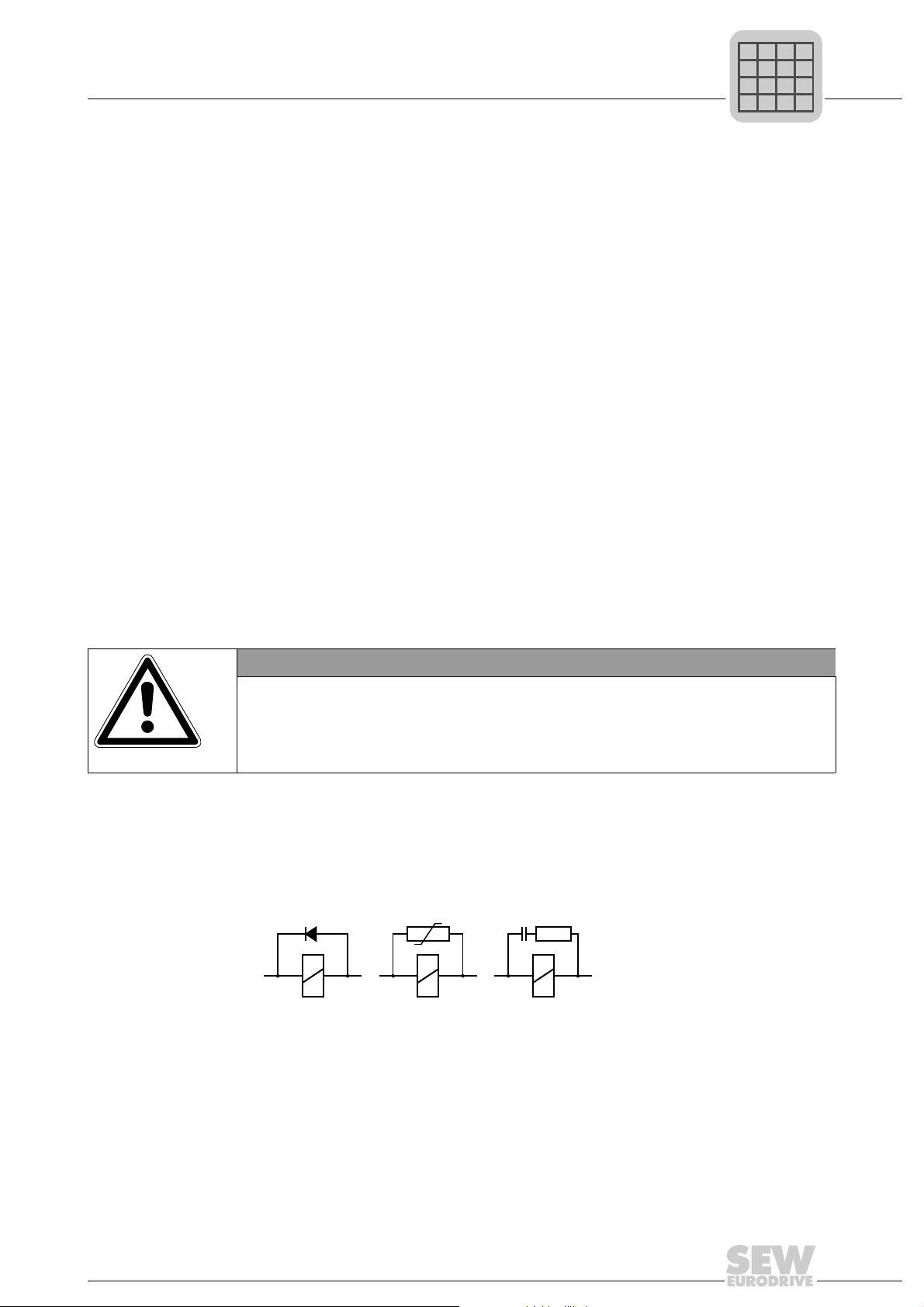
4.2.14 Switched inductances
• Use suppressors to suppress interference on
– Contactors
–Relays
– Solenoid valves
Suppressors are, for example, diodes, varistors, or RC elements:
Do not connect any suppressors directly on MOVITRAC
®
B. Connect suppressors as
closely as possible to the inductance.
NOTICE
Switched inductances
Hazard: Malfunctions / damage to property.
Measure: The minimum distance of switched inductances to the inverter must be at
least 150 mm (5.91 in).
P
i
f
kVA
Hz
n
Phone: 800.894.0412 - Fax: 888.723.4773 - Web: www.clrwtr.com - Email: info@clrwtr.com
20
Operating Instructions V3 – MOVITRAC® B
4
Installation notes
Installation
4.2.15 Line filters
MOVITRAC
®
B frequency inverters have an integrated line filter as standard. They
comply with the following limit value class to EN 55011 on the line side without further
measures:
• Single-phase connection: C1 cable conducted
• Three-phase connection: C2
No EMC limits are specified for interference emission in voltage suply systems without
an earthed star point (IT system). The efficiency of line filters is severely limited.
4.2.16 Line protection and earth-leakage circuit breaker
• Install fuses at the beginning of the mains cable behind supply bus junction (see
basic unit wiring diagram).
• SEW-EURODRIVE recommends that you do not use earth-leakage circuit breakers.
However, if an earth-leakage circuit breaker is stipulated for direct or indirect
protection against contact, observe the following:
4.2.17 PE input connect io n
Earth-leakage currents ≥ 3.5 mA may occur during normal operation. Observe the
following for reliable PE connection:
• Power supply cable < 10 mm
2
(AWG7):
– Route a second PE conductor with the same cross section as the power supply
cable in parallel to the protective earth via separate terminals, or
– Use a copper protective earth conductor with a cross section of 10 mm
2
(AWG7)
• Power supply cable 10 mm
2
– 16 mm
2
(AWG7 – AWG5):
– Copper protective earth conductor with the cross section of the power supply
cable.
• Power supply cable 16 mm
2
– 35 mm
2
(AWG5 – AWG2):
– Copper protective earth conductor with a cross section of 16 mm
2
(AWG5)
• Power supply cable > 35 mm
2
(AWG2):
– Copper protective earth co nductor with half the cross section of the power supply
cable.
TIP
Use only type B earth-leakage circuit breakers.
MOVITRAC
®
can cause direct current in the protective earth. In ca ses where an earth-
leakage circuit breaker is used for protection against direct or indirect contact, only
install a type B earth-leakage circuit breaker on the power supply end of the
MOVITRAC
®
unit.
P
i
f
kVA
Hz
n
Phone: 800.894.0412 - Fax: 888.723.4773 - Web: www.clrwtr.com - Email: info@clrwtr.com
Operating Instructions V3 – MOVITRAC® B
21
4
Installing optional power components
Installation
4.3 Installing optional power components
Input contactor for several units
Connect a line choke for limiting the inrush current:
• For 5 or more 3-phase units
• For 2 or more 1-phase units
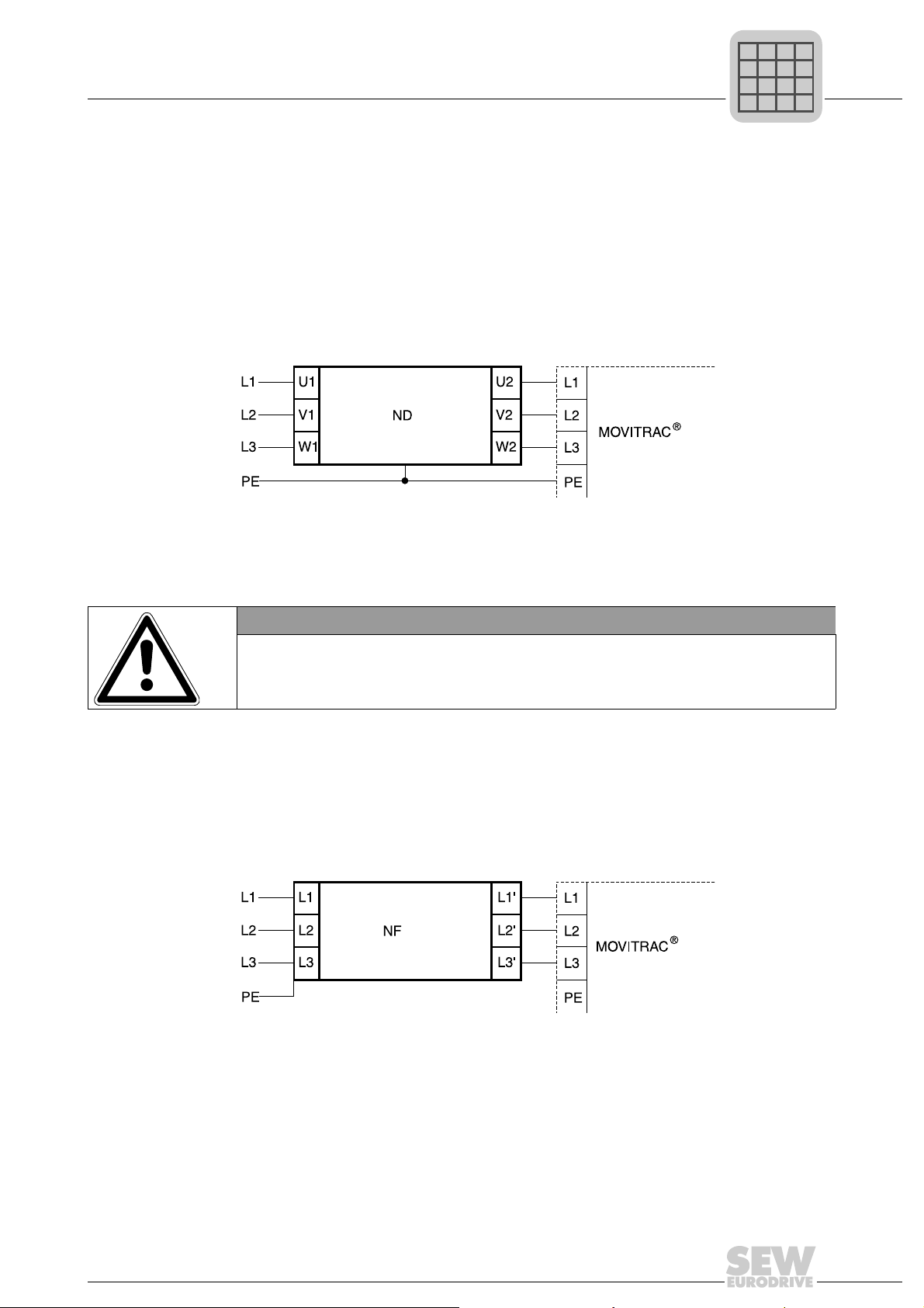
4.3.1 ND line choke
Connecting ND series line choke
4.3.2 NF line filter
• Using the NF line filter, you can maintain limit value class C1 / B with MOVITRAC
®
B sizes 0 to 4.
• Install the line filter close to the inverter but outside the minimum clearance for
cooling.
• Restrict the cable between the line filter and the inverter to the absolute minimum
length required, and never more than 400 mm (15.7 in). Unshielded, twisted cables
are sufficient.
• Use also unshielded lines for the power supply cable.
Connecting NF line filters
4.3.3 ULF11A folding ferrites
Place the supply system cable (L and N) in the folding ferrite and press the folding
ferrites together until they snap in place.
Compliance with EMC limit class C1 has been tested on a specified test setup.
Compliance with class C1 for signal interference is achieved by the proper installation
of ULF11A folding ferrites.
B
NOTICE
Possible damage to property
No switching is permitted between the line filter and MOVITRAC
®
.
• Consequences if disregarded: Damage to the input stage.
B
P
i
f
kVA
Hz
n
Phone: 800.894.0412 - Fax: 888.723.4773 - Web: www.clrwtr.com - Email: info@clrwtr.com
22
Operating Instructions V3 – MOVITRAC® B
4
Installing optional power components
Installation
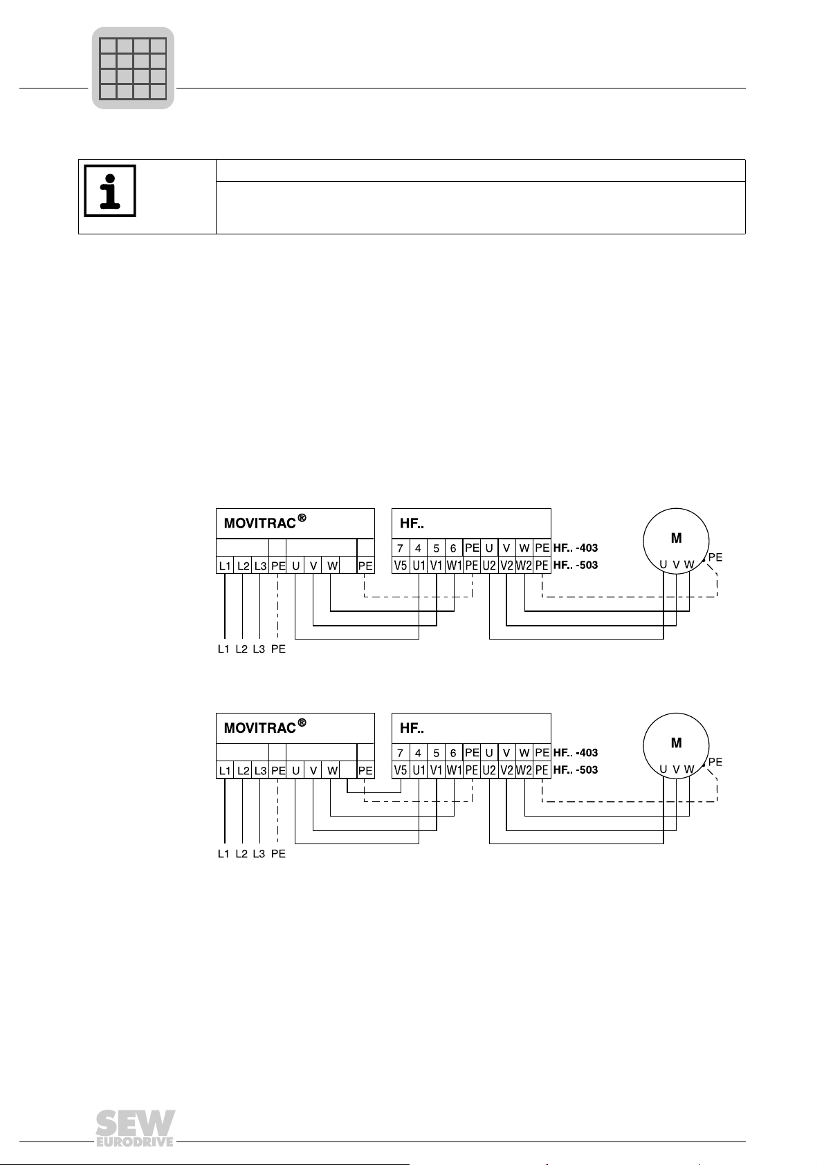
4.3.4 HF output filters
• Limit the length of the cable between inverter and output filter to the absolute
minimum needed. Maximum 1 m / 3 ft with unshielded cable, 10 m / 33 ft with
shielded cable.
• Several motors can be connected to one output filter when operating a motor group
from one inverter. The total value of the rated motor currents must not exceed the
rated throughput current of the output filter.
• Two identical output filters can be connected in parallel to one inverter output to
double the rated throughput current. To do this, connect all like connections to the
output filters in parallel.
• If you operate the inverter with f
PWM
= 4 or 8 kHz, do not connect th e output filter
connection V5 (wtih HF..-503) or 7 (with HF..-403).
•No V
DC link
connection is permitted for size 0XS units.
HF output filter connection without V
DC link
connection (PWM frequency only 4 or 8 kHz)
HF output filter connection without V
DC link
connection (PWM frequency only 12 or
16 kHz)
TIP
• Install output filters next to the corresponding inverter . Leave a ventilation space of
at least 100 mm (3.94 in) below and above the output filter. No clearance is
required on the sides.
B
+R
X2/3
X1
B
+R
X2/3
X1
P
i
f
kVA
Hz
n
Phone: 800.894.0412 - Fax: 888.723.4773 - Web: www.clrwtr.com - Email: info@clrwtr.com
Operating Instructions V3 – MOVITRAC® B
23
4
Installing optional power components
Installation
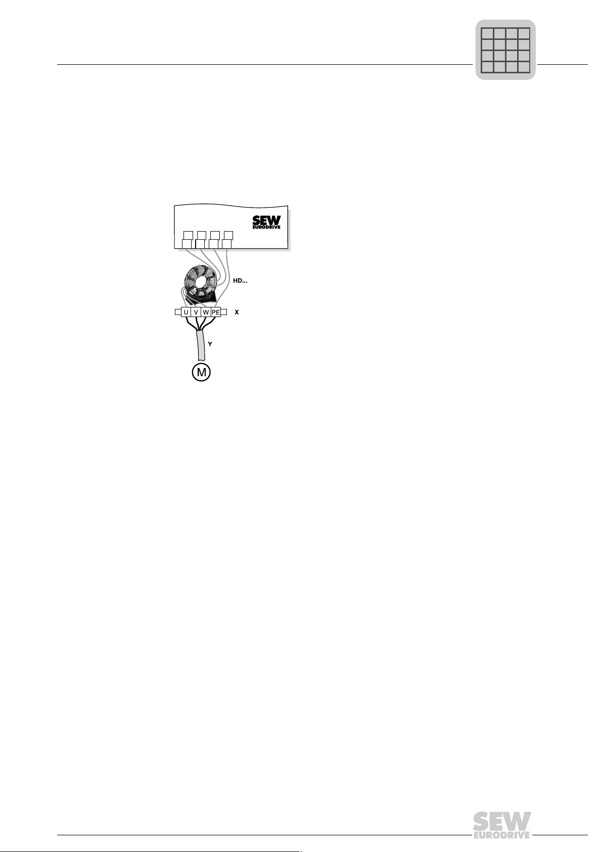
4.3.5 HD output choke
• Install the output choke close to MOVITRAC
®
B beyond the minimum clearance.
• Always route all 3 phases (not PE!) through the output choke.
• If the cable is shielded, the shield should not be routed through the output choke.
When using the HD output choke, you have to wrap the cable around the choke 5
times.
Only 5 loops are possible if the cable has a large diameter. To make up for this, 2 or
3 output chokes should be connected in series. SEW recommends connecting in
series 2 output chokes in case of 4 windings and 3 output chokes in case of 3
windings.
• Installing HD012 output choke:
Install the output choke under the associated inverter. Leave a ventilation space of
at least 100 mm (3.94 in) below and above the output choke. Provide a clearance of
10 mm (0.39 in) on each side.
Three alternative connection options are provided for connecting the protective
earth. You can connect the PE line of the motor cable directly on the frequency
inverter.
n = 5
456
댷
UVWPE
P
i
f
kVA
Hz
n
Phone: 800.894.0412 - Fax: 888.723.4773 - Web: www.clrwtr.com - Email: info@clrwtr.com
24
Operating Instructions V3 – MOVITRAC® B
4
Installing optional power components
Installation
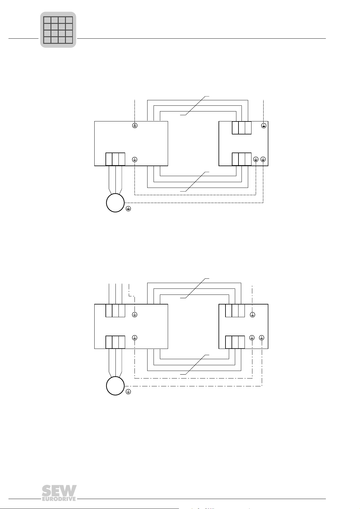
Installing output
choke HD100 /
HD101
Use the supplied screws to mount the HD100 / HD101 output choke together with the
MOVITRAC B frequency inverter onto the conductive mounting surface in the control
cabinet.
The connections U / V / W are labeled U / V / W and have to be connected accordingly.
4.3.6 FKE12B / FKE13B EMC-modules
Use the supplied screws to mount the EMC module together with the MOVITRAC
®
B
frequency inverter onto the conductive mounting surface in the control cabinet.
The connections U / V / W are labeled U / V / W and have to be connected accordingly.
The connections L1 / L2 / L3 (brown / orange / white) can be connected in any order.
U V W
PE
M
3
~
HD100 / HD101
L1 L2 L3
U V W
MOVITRAC
®
B
PE
PE
PE
L1L2 L3
U V W
PE
PE
M
3
~
FKE
L1L2 L3
U V W
MOVITRAC
®
B
PE
PE
P
i
f
kVA
Hz
n
Phone: 800.894.0412 - Fax: 888.723.4773 - Web: www.clrwtr.com - Email: info@clrwtr.com
Operating Instructions V3 – MOVITRAC® B
25
4
Installing optional power components
Installation
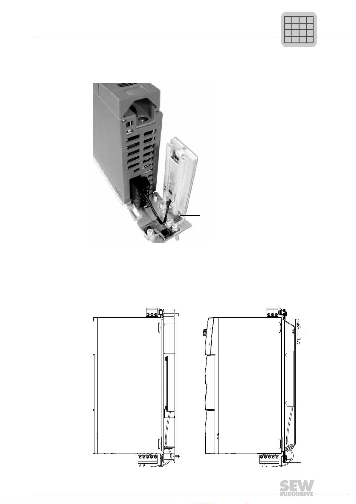
4.3.7 PTC braking resistors BW1 / BW3 with FKB10B
BW1 and BW3 PTC braking resistors [1] can be mounted to the shield plate under the
inverter using the angle bracket FKB10B [2], part number 18216218 available as option.
4.3.8 Flat-design resistors with FKB11B / FKB12B / FKB13B and FHS11B / FHS12B / FHS13B
Flat-design braking resistors can be installed as follows:
• Installation on the back panel of the control cabinet: FKB11B / FKB12B / FKB13B
• Installation with mounting rail: FHS11B / FHS12B / FHS13B
[1]
[2]
FKB11B
FKB12B
FKB13B
FHS11B
FHS12B
FHS13B
P
i
f
kVA
Hz
n

26
Operating Instructions V3 – MOVITRAC® B
4
UL compliant installation
Installation
4.4 UL compliant installation
Note the following points for UL-compliant installation:
• Only use copper cables with the following temperature rang es as connection cabl es:
–MOVITRAC
®
B 0003 – 0300: Temperature range 60/75 °C (140/167 °F)
–MOVITRAC
®
B 0370 and 0450: Temperature range 75 °C (167 °F)
• Necessary tightening torques of MOVITRAC
®
B power terminals: See technical data.
• Operate the inverters on supply systems with a maximum phase-to-earth voltage of
AC 300 V only.
• The inverter can only be operated on IT systems if the phase-to-earth voltage of
AC 3 00 V ca nno t be ex ce ed ed eith er du rin g op er at ion or in case of an er ro r.
•MOVITRAC
®
B frequency inverters are only allowed to be operated on supply
systems which can supply maximum values in accordance with the following table.
Only use melting fuses. The performance data of the fuses must not exceed the
values in the following table.
P
i
f
kVA
Hz
n
Phone: 800.894.0412 - Fax: 888.723.4773 - Web: www.clrwtr.com - Email: info@clrwtr.com
Operating Instructions V3 – MOVITRAC® B
27
4
UL compliant installation
Installation
4.4.1 Maximum values/fuses
The following maximum values/fuses must be observed for UL compliant installation:
230 V units / 1-phase Max. mains current Max. mains voltage Fuses
0003 / 0004 / 0005 / 0008 AC 5000 A AC 240 V 15 A / 250 V
0011 / 0015 / 0022 AC 5000 A AC 240 V 30 A / 250 V
230 V units / 3-phase Max. mains current Max. mains voltage Fuses
0003 / 0004 / 0005 / 0008 AC 5000 A AC 240 V 15 A / 250 V
0011 / 0015 / 0022 AC 5000 A AC 240 V 20 A / 250 V
0037 AC 5000 A AC 240 V 30 A / 250 V
0055 / 0075 AC 5000 A AC 240 V 110 A / 250 V
0110 AC 5000 A AC 240 V 175 A / 250 V
0150 AC 5000 A AC 240 V 225 A / 250 V
0220 / 0300 AC 10000 A AC 240 V 350 A / 250 V
400/500 V units Max. mains current Max. mains vo ltage Fuses
0003 / 0004 / 0005 / 0008 /
0011 / 0015
AC 5000 A AC 500 V 15 A / 600 V
0022 / 0030 / 0040 AC 5000 A AC 500 V 20 A / 600 V
0055 / 0075 AC 5000 A AC 500 V 60 A / 600 V
0110 AC 5000 A AC 500 V 110 A / 600 V
0150 / 0220 AC 5000 A AC 500 V 175 A / 600 V
0300 AC 5000 A AC 500 V 225 A / 600 V
0370 / 0450 AC 10000 A AC 500 V 350 A / 600 V
0550 / 0750 AC 10000 A AC 500 V 500 A / 600 V
TIPS
• Use only tested units with a limited output voltage (V
max
= DC 30 V) and limited
output current (I ≤ 8 A) as an external DC 24 V voltage source.
• UL certification does not apply to operation in voltag e supply systems with a non-
grounded star point (IT systems).
P
i
f
kVA
Hz
n
Phone: 800.894.0412 - Fax: 888.723.4773 - Web: www.clrwtr.com - Email: info@clrwtr.com
28
Operating Instructions V3 – MOVITRAC® B
4
Installation of loose items
Installation
4.5 Installation of loose items
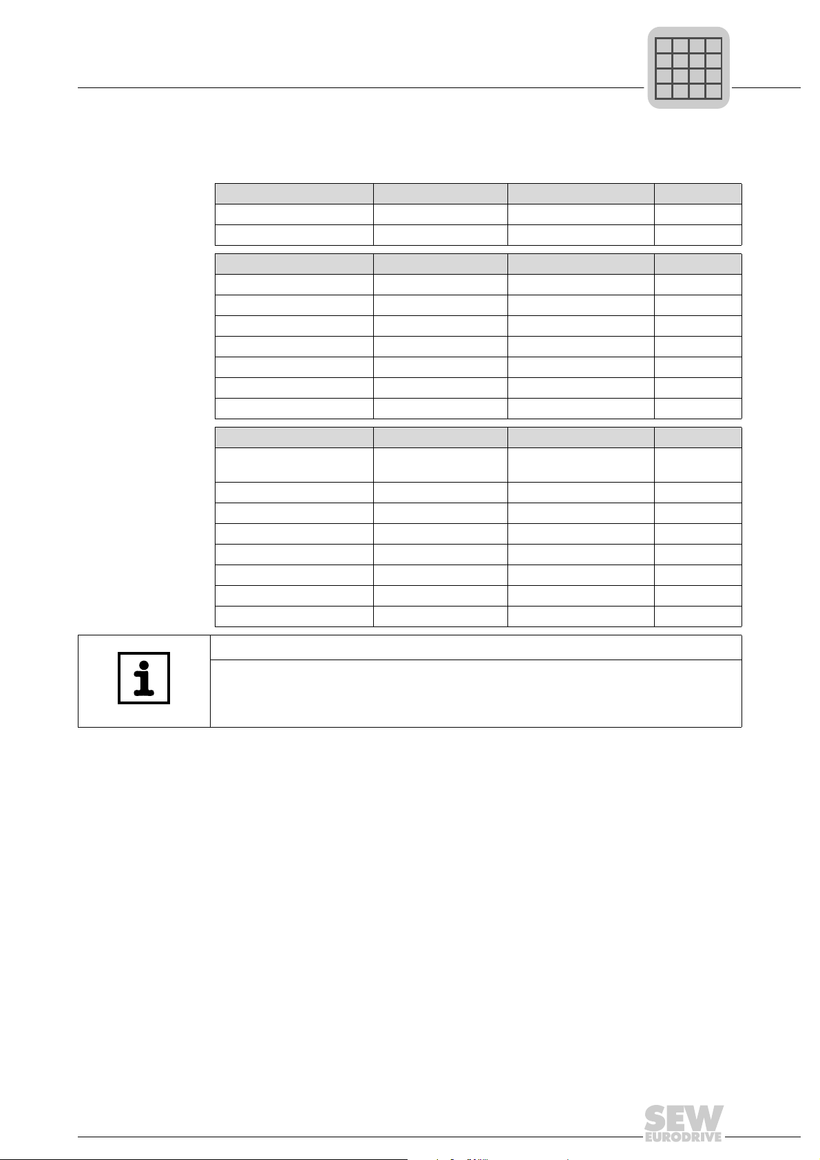
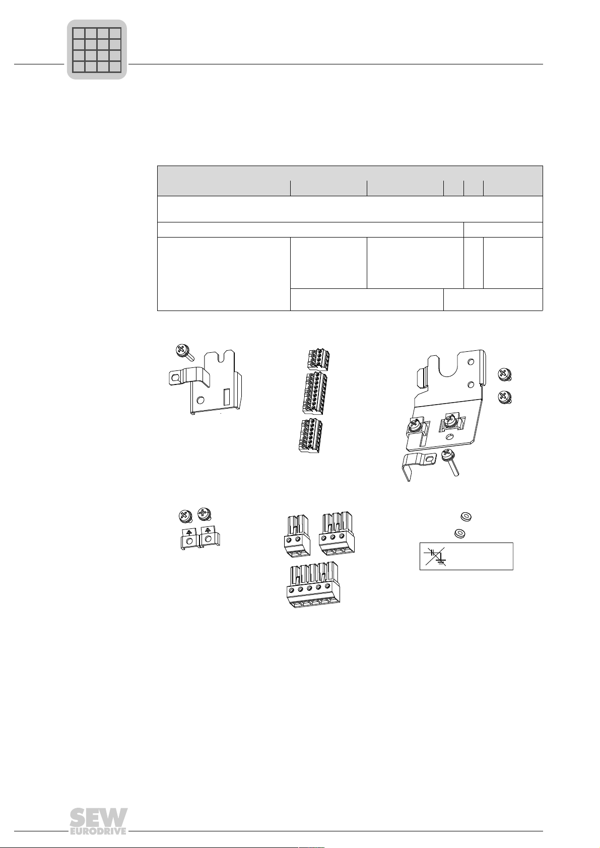
4.5.1 Scope of delivery of loose items
The scope of delivery includes a bag for loose items. Its contents depends on the size
of the inverter.
Loose items for size 0:
Scope of delivery of loose items for size
0XS / 0S / 0L 1 2S 2 3 4 / 5
• Shield plate for control electronics with clamps and screws [1]
• 3 connectors for electronics terminals [2]
• Grounding terminals with screws [4] –
• Shield plate for the power
section with clamps and
screws [3]
• Connector for mains (2 or
3-pole) and motor [5]
• Plastic insulation s with
stickers [6]
• Shield plate
for the power
section
without
screws
• Touch guard
• Shield plate for
the power section
with screws
– • Touch
guard
• Fixing straps –
"#!#%!#
#!"#%#
"#$!"&"#%&"
P
i
f
kVA
Hz
n
Phone: 800.894.0412 - Fax: 888.723.4773 - Web: www.clrwtr.com - Email: info@clrwtr.com
Operating Instructions V3 – MOVITRAC® B
29
4
Installation of loose items
Installation
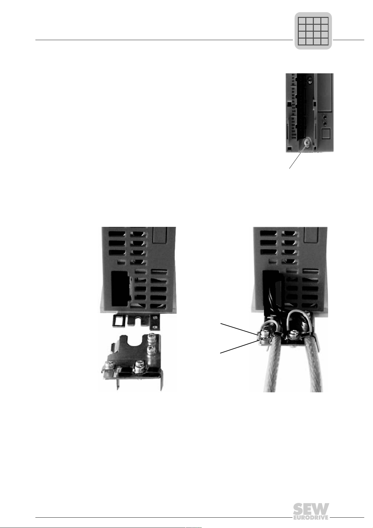
4.5.2 Installing shield plate for cont rol electronics (all sizes)
MOVITRAC
®
B includes a shield plate for the control electron-
ics with a retaining screw as standard. Install the shield plate for
control electronics as follows:
1. Loosen the screw first [1].
2. Insert the shield clamp into the slot in the plastic housing.
3. Fasten the shield clamp.
4.5.3 Installing shield plate for power section
Size 0 A power shield plate for the power section with 2 retaining screws is supplied as
standard with MOVITRAC
®
size 0.
Mount the shield plate for the power section using the two retaining screws.
[1]
[1] PE connection [2] Shield plate
[1]
[2]
P
i
f
kVA
Hz
n
Phone: 800.894.0412 - Fax: 888.723.4773 - Web: www.clrwtr.com - Email: info@clrwtr.com
30
Operating Instructions V3 – MOVITRAC® B
4
Installation of loose items
Installation
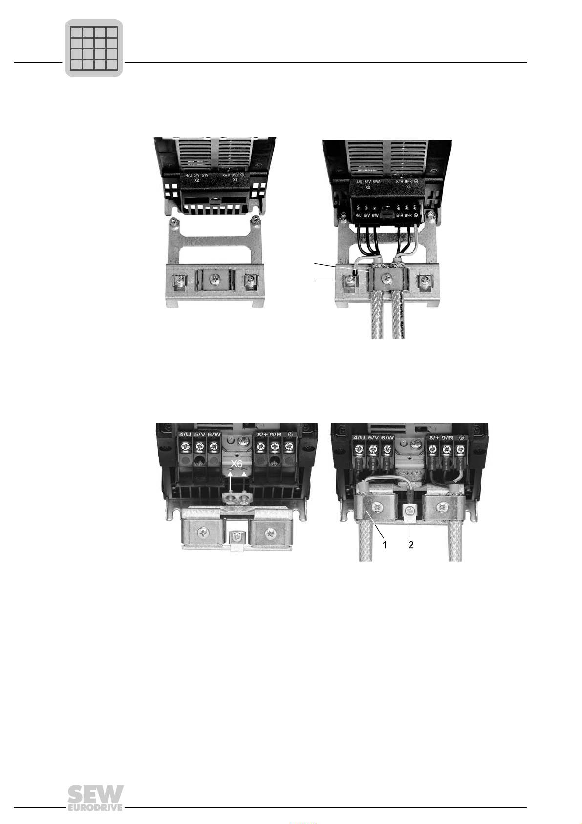
Size 1 SEW-EURODRIVE supplies a shield plate for the power section as standard with
MOVITRAC
®
B size 1. Mount the shield plate for the power section using the unit's two
retaining screws.
Sizes 2S / 2 SEW-EURODRIVE supplies a shield plate for the power section with two retaining
screws as standard with MOVITRAC
®
B sizes 2S / 2. Mount the shield plate for the
power section using the two retaining screws. The illustration shows size 2.
The shield plate for the power section provides you with a very convenient way of install-
ing the shield for the motor and brake cables. Apply the shield and PE conductor as
shown in the figures below.
Sizes 3 – 5 No shield plates for the power section are supplied with MOVITRAC
®
B sizes 3 to 5. Use
commercially available shield clamps for installing the shielding of motor and brake
cables. Apply the shield as closely as possible to the inverter.
[1] Shield clamp [2] PE connection
[1]
[2]
[1] Shield clamp [2] PE connection
P
i
f
kVA
Hz
n
Phone: 800.894.0412 - Fax: 888.723.4773 - Web: www.clrwtr.com - Email: info@clrwtr.com
 Loading...