

Page 1
Modicon M251 Logic C ontroller
EIO0000003101 12/2019
Modicon M251 Logic
Controller
Hardware Guide
12/2019
EIO0000003101.01
www.schneider-electric.com
Page 2

The information provided in this documentation contains general descriptions and/or technical
characteristics of the performance of the products contained herein. This documentation is not
intended as a substitute for and is not to be used for determining suitability or reliability of these
products for specific user applications. It is the duty of any such user or integrator to perform the
appropriate and complete risk analysis, evaluation and testing of the products with respect to the
relevant specific application or use thereof. Neither Schneider Electric nor any of its affiliates or
subsidiaries shall be responsible or liable for misuse of the information contained herein. If you
have any suggestions for improvements or amendments or have found errors in this publication,
please notify us.
You agree not to reproduce, other than for your own personal, noncommercial use, all or part of
this document on any medium whatsoever without permission of Schneider Electric, given in
writing. You also agree not to establish any hypertext links to this document or its content.
Schneider Electric does not grant any right or license for the personal and noncommercial use of
the document or its content, except for a non-exclusive license to consult it on an "as is" basis, at
your own risk. All other rights are reserved.
All pertinent state, regional, and local safety regulations must be observed when installing and
using this product. For reasons of safety and to help ensure compliance with documented system
data, only the manufacturer should perform repairs to components.
When devices are used for applications with technical safety requirements, the relevant
instructions must be followed.
Failure to use Schneider Electric software or approved software with our hardware products may
result in injury, harm, or improper operating results.
Failure to observe this information can result in injury or equipment damage.
© 2019 Schneider Electric. All rights reserved.
2 EIO0000003101 12/2019
Page 3

Table of Contents
Safety Information. . . . . . . . . . . . . . . . . . . . . . . . . . . . . . 5
About the Book . . . . . . . . . . . . . . . . . . . . . . . . . . . . . . . . 7
Part I Modicon M251 Logic Controller Introduction . . . . . .
Chapter 1 M251 General Overview . . . . . . . . . . . . . . . . . . . . . . . . . 17
M251 Logic Controller Description . . . . . . . . . . . . . . . . . . . . . . . . . . .
Maximum Hardware Configuration . . . . . . . . . . . . . . . . . . . . . . . . . . .
TM2 Expansion Modules . . . . . . . . . . . . . . . . . . . . . . . . . . . . . . . . . . .
TM3 Expansion Modules . . . . . . . . . . . . . . . . . . . . . . . . . . . . . . . . . . .
TM3 Bus Couplers. . . . . . . . . . . . . . . . . . . . . . . . . . . . . . . . . . . . . . . .
TM4 Expansion Modules . . . . . . . . . . . . . . . . . . . . . . . . . . . . . . . . . . .
TM5 Fieldbus Interfaces . . . . . . . . . . . . . . . . . . . . . . . . . . . . . . . . . . .
TM5 CANopen Fieldbus Interfaces . . . . . . . . . . . . . . . . . . . . . . . . . . .
TM7 CANopen Fieldbus Interfaces . . . . . . . . . . . . . . . . . . . . . . . . . . .
Accessories . . . . . . . . . . . . . . . . . . . . . . . . . . . . . . . . . . . . . . . . . . . . .
Chapter 2 M251 Features . . . . . . . . . . . . . . . . . . . . . . . . . . . . . . . . 43
Real Time Clock (RTC) . . . . . . . . . . . . . . . . . . . . . . . . . . . . . . . . . . . .
Run/Stop . . . . . . . . . . . . . . . . . . . . . . . . . . . . . . . . . . . . . . . . . . . . . . .
SD Card . . . . . . . . . . . . . . . . . . . . . . . . . . . . . . . . . . . . . . . . . . . . . . .
Chapter 3 M251 Installation . . . . . . . . . . . . . . . . . . . . . . . . . . . . . . 53
3.1 M251 Logic Controller General Rules for Implementing . . . . . . . . . . .
Environmental Characteristics. . . . . . . . . . . . . . . . . . . . . . . . . . . . . . .
Certifications and Standards . . . . . . . . . . . . . . . . . . . . . . . . . . . . . . . .
3.2 M251 Logic Controller Installation . . . . . . . . . . . . . . . . . . . . . . . . . . . .
Installation and Maintenance Requirements . . . . . . . . . . . . . . . . . . . .
M251 Logic Controller Mounting Positions and Clearances . . . . . . . .
Top Hat Section Rail (DIN rail) . . . . . . . . . . . . . . . . . . . . . . . . . . . . . .
Installing and Removing the Controller with Expansions. . . . . . . . . . .
Direct Mounting on a Panel Surface . . . . . . . . . . . . . . . . . . . . . . . . . .
3.3 M251 Electrical Requirements. . . . . . . . . . . . . . . . . . . . . . . . . . . . . . .
Wiring Best Practices . . . . . . . . . . . . . . . . . . . . . . . . . . . . . . . . . . . . .
DC Power Supply Characteristics and Wiring . . . . . . . . . . . . . . . . . . .
Grounding the M251 System. . . . . . . . . . . . . . . . . . . . . . . . . . . . . . . .
15
18
20
23
27
36
37
38
39
40
41
44
48
49
54
55
58
59
60
63
66
70
73
74
75
78
82
EIO0000003101 12/2019 3
Page 4

Part II Modicon M251 Logic Controller . . . . . . . . . . . . . . . .
85
Chapter 4 TM251MESC . . . . . . . . . . . . . . . . . . . . . . . . . . . . . . . . . . 87
TM251MESC Presentation . . . . . . . . . . . . . . . . . . . . . . . . . . . . . . . . .
87
Chapter 5 TM251MESE . . . . . . . . . . . . . . . . . . . . . . . . . . . . . . . . . . 91
TM251MESE Presentation . . . . . . . . . . . . . . . . . . . . . . . . . . . . . . . . .
Part III Modicon M251 Logic Controller Communication . . .
91
95
Chapter 6 Integrated Communication Ports . . . . . . . . . . . . . . . . . . . 97
CAN Port . . . . . . . . . . . . . . . . . . . . . . . . . . . . . . . . . . . . . . . . . . . . . . .
Ethernet Port . . . . . . . . . . . . . . . . . . . . . . . . . . . . . . . . . . . . . . . . . . . .
TM251MESE Specific Considerations . . . . . . . . . . . . . . . . . . . . . . . . .
USB Mini-B Programming Port . . . . . . . . . . . . . . . . . . . . . . . . . . . . . .
Serial Line . . . . . . . . . . . . . . . . . . . . . . . . . . . . . . . . . . . . . . . . . . . . . .
98
101
103
105
106
Chapter 7 Connecting the M251 Logic Controller to a PC . . . . . . . . 109
Connecting the Controller to a PC . . . . . . . . . . . . . . . . . . . . . . . . . . . .
Glossary . . . . . . . . . . . . . . . . . . . . . . . . . . . . . . . . . . . . . . . . .
Index . . . . . . . . . . . . . . . . . . . . . . . . . . . . . . . . . . . . . . . . .
109
113
119
4 EIO0000003101 12/2019
Page 5
Safety Information
Important Information
NOTICE
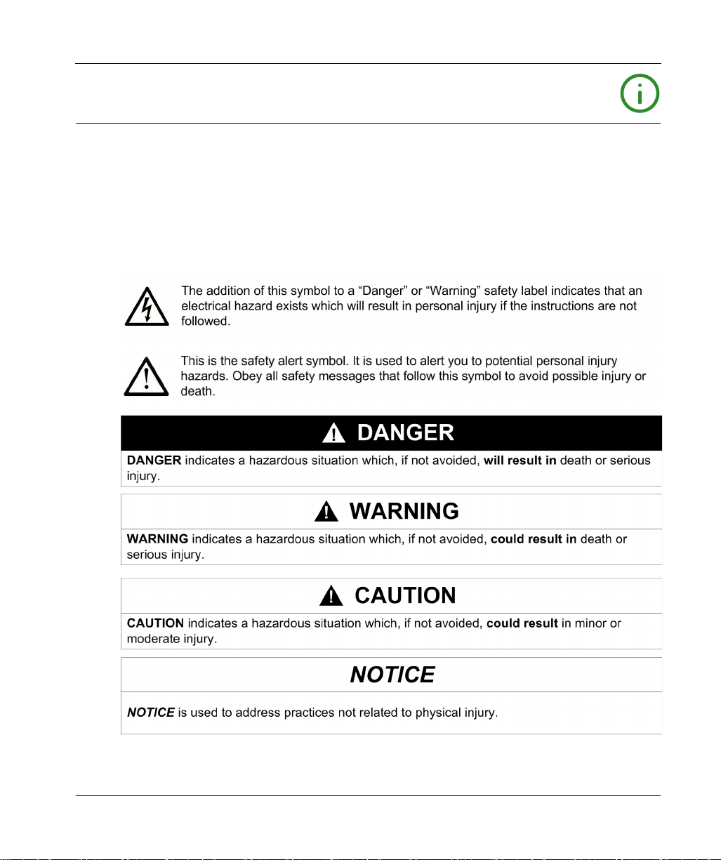
Read these instructions carefully, and look at the equipment to become familiar with the device
before trying to install, operate, service, or maintain it. The following special messages may appear
throughout this documentation or on the equipment to warn of potential hazards or to call attention
to information that clarifies or simplifies a procedure.
EIO0000003101 12/2019 5
Page 6

PLEASE NOTE
Electrical equipment should be installed, operated, serviced, and maintained only by qualified
personnel. No responsibility is assumed by Schneider Electric for any consequences arising out of
the use of this material.
A qualified person is one who has skills and knowledge related to the construction and operation
of electrical equipment and its installation, and has received safety training to recognize and avoid
the hazards involved.
QUALIFICATION OF PERSONNEL
Only appropriately trained persons who are familiar with and understand the contents of this
manual and all other pertinent product documentation are authorized to work on and with this
product.
The qualified person must be able to detect possible hazards that may arise from parameterization,
modifying parameter values and generally from mechanical, electrical, or electronic equipment.
The qualified person must be familiar with the standards, provisions, and regulations for the
prevention of industrial accidents, which they must observe when designing and implementing the
system.
INTENDED USE
The products described or affected by this document, together with software, accessories, and
options, are programmable logic controllers (referred to herein as “logic controllers”), intended for
industrial use according to the instructions, directions, examples, and safety information contained
in the present document and other supporting documentation.
The product may only be used in compliance with all applicable safety regulations and directives,
the specified requirements, and the technical data.
Prior to using the product, you must perform a risk assessment in view of the planned application.
Based on the results, the appropriate safety-related measures must be implemented.
Since the product is used as a component in an overall machine or process, you must ensure the
safety of persons by means of the design of this overall system.
Operate the product only with the specified cables and accessories. Use only genuine accessories
and spare parts.
Any use other than the use explicitly permitted is prohibited and can result in unanticipated
hazards.
6 EIO0000003101 12/2019
Page 7

About the Book
At a Glance
Document Scope
Use this document to:
Install and operate your M251 Logic Controller.
Connect the M251 Logic Controller to a programming device equipped with EcoStruxure
Machine Expert software.
Interface the M251 Logic Controller with I/O expansion modules, HMI and other devices.
Familiarize yourself with the M251 Logic Controller features.
NOTE: Read and understand this document and all related documents before installing, operating,
or maintaining your controller.
Validity Note
This document has been updated for the release of EcoStruxure
For product compliance and environmental information (RoHS, REACH, PEP, EOLI, etc.), go to
www.schneider-electric.com/green-premium
The technical characteristics of the devices described in this manual also appear online
https://www.se.com/
(
The characteristics that are described in the present document should be the same as those
characteristics that appear online. In line with our policy of constant improvement, we may revise
content over time to improve clarity and accuracy. If you see a difference between the document
and online information, use the online information as your reference.
TM
Machine Expert V1.2.
.
).
EIO0000003101 12/2019 7
Page 8

Related Documents
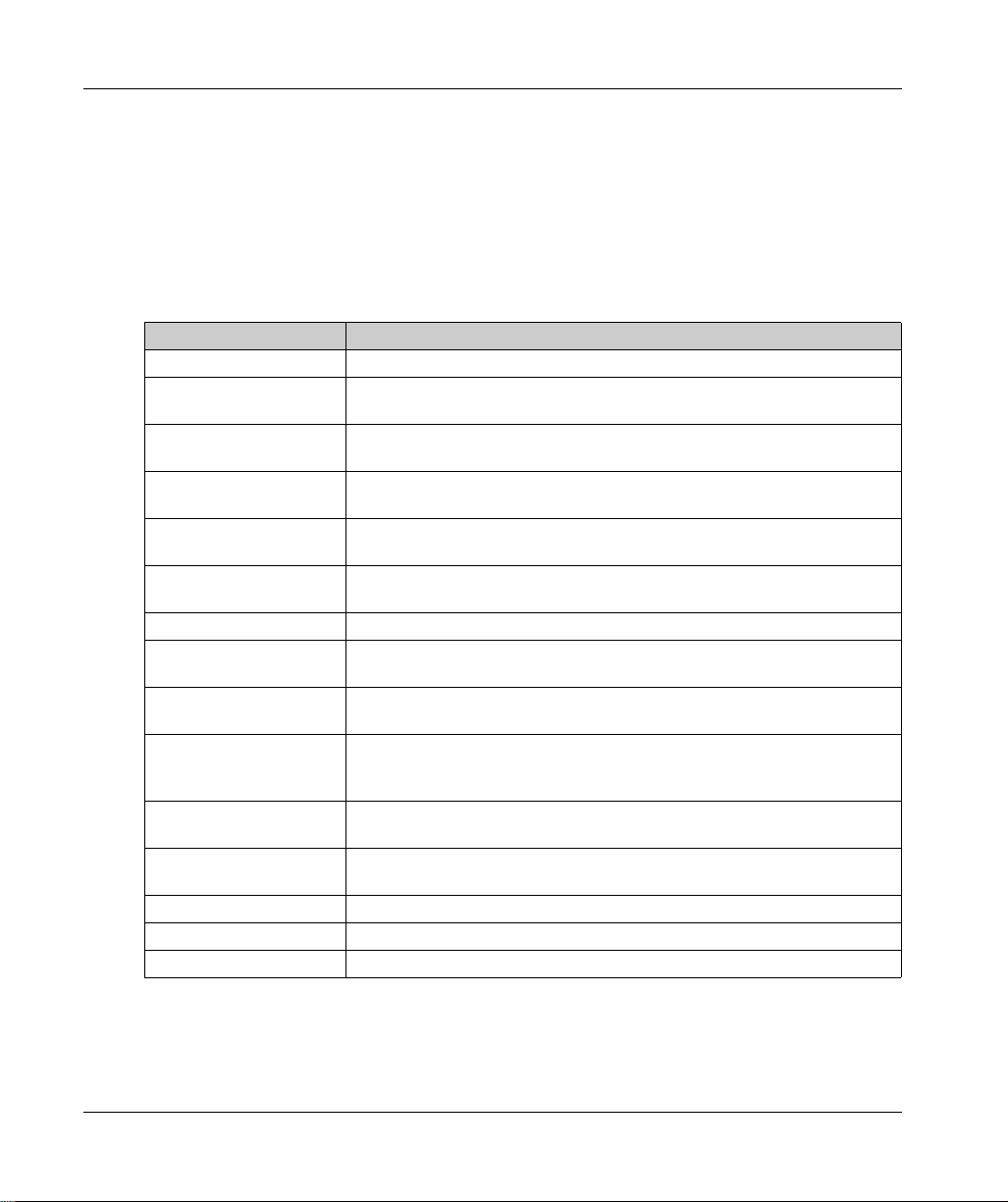
Title of Documentation Reference Number
Modicon M251 Logic Controller - Programming Guide
EcoStruxure Machine Expert Industrial Ethernet User Guide
Modicon TM3 Digital I/O Modules - Hardware Guide
Modicon TM3 Expert I/O Modules - Hardware Guide
Modicon TM3 Safety Modules - Hardware Guide
EIO0000003089 (ENG)
EIO0000003090 (FRE)
EIO0000003091 (GER)
EIO0000003092 (SPA)
EIO0000003093 (ITA)
EIO0000003094 (CHS)
EIO0000003053 (ENG)
EIO0000003054 (FRE)
EIO0000003055 (GER)
EIO0000003056 (SPA)
EIO0000003057 (ITA)
EIO0000003058 (CHS)
EIO0000003125 (ENG)
EIO0000003126 (FRE)
EIO0000003127 (GER)
EIO0000003128 (SPA)
EIO0000003129 (ITA)
EIO0000003130 (CHS)
EIO0000003425 (TUR)
EIO0000003424 (POR)
EIO0000003137 (ENG)
EIO0000003138 (FRE)
EIO0000003139 (GER)
EIO0000003140 (SPA)
EIO0000003141 (ITA)
EIO0000003142 (CHS)
EIO0000003429 (TUR)
EIO0000003428 (POR)
EIO0000003353 (ENG)
EIO0000003354 (FRE)
EIO0000003355 (GER)
EIO0000003356 (SPA)
EIO0000003357 (ITA)
EIO0000003358 (CHS)
EIO0000003359 (POR)
EIO0000003360 (TUR)
8 EIO0000003101 12/2019
Page 9

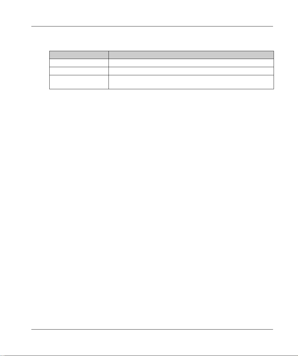
Title of Documentation Reference Number
Modicon TM3 Transmitter and Receiver Modules - Hardware Guide
EIO0000003143 (ENG)
EIO0000003144 (FRE)
EIO0000003145 (GER)
EIO0000003146 (SPA)
EIO0000003147 (ITA)
EIO0000003148 (CHS)
EIO0000003431 (TUR)
EIO0000003430 (POR)
Modicon TM3 Bus Coupler - Hardware Guide
EIO0000003635 (ENG)
EIO0000003636 (FRE)
EIO0000003637 (GER)
EIO0000003638 (SPA)
EIO0000003639 (ITA)
EIO0000003640 (CHS)
EIO0000003641 (POR)
EIO0000003642 (TUR)
Modicon TM4 Expansion Modules - Hardware Guide
EIO0000003155 (ENG)
EIO0000003156 (FRE)
EIO0000003157 (GER)
EIO0000003158 (SPA)
EIO0000003159 (ITA)
EIO0000003160 (CHS)
Modicon TM5 Fieldbus Interface - Hardware Guide
EIO0000003715 (ENG)
EIO0000003716 (FRE)
EIO0000003717 (GER)
EIO0000003718 (SPA)
EIO0000003719 (ITA)
EIO0000003720 (CHS)
M251 Logic Controller - Instruction Sheet
HRB59604
You can download these technical publications and other technical information from our website
at https://www.se.com/ww/en/download/ .
EIO0000003101 12/2019 9
Page 10

Product Related Information
HAZARD OF ELECTRIC SHOCK, EXPLOSION OR ARC FLASH
Disconnect all power from all equipment including connected devices prior to removing any
covers or doors, or installing or removing any accessories, hardware, cables, or wires except
under the specific conditions specified in the appropriate hardware guide for this equipment.
Always use a properly rated voltage sensing device to confirm the power is off where and when
indicated.
Replace and secure all covers, accessories, hardware, cables, and wires and confirm that a
proper ground connection exists before applying power to the unit.
Use only the specified voltage when operating this equipment and any associated products.
Failure to follow these instructions will result in death or serious injury.
POTENTIAL FOR EXPLOSION
Only use this equipment in non-hazardous locations, or in locations that comply with Class I,
Division 2, Groups A, B, C and D.
Do not substitute components which would impair compliance to Class I, Division 2.
Do not connect or disconnect equipment unless power has been removed or the location is
known to be non-hazardous.
Do not use the USB port(s), if so equipped, unless the location is known to be non-hazardous.
Failure to follow these instructions will result in death or serious injury.
DANGER
DANGER
10 EIO0000003101 12/2019
Page 11

WARNING
LOSS OF CONTROL
The designer of any control scheme must consider the potential failure modes of control paths
and, for certain critical control functions, provide a means to achieve a safe state during and
after a path failure. Examples of critical control functions are emergency stop and overtravel
stop, power outage and restart.
Separate or redundant control paths must be provided for critical control functions.
System control paths may include communication links. Consideration must be given to the
implications of unanticipated transmission delays or failures of the link.
Observe all accident prevention regulations and local safety guidelines.
Each implementation of this equipment must be individually and thoroughly tested for proper
1
operation before being placed into service.
Failure to follow these instructions can result in death, serious injury, or equipment damage.
1
For additional information, refer to NEMA ICS 1.1 (latest edition), "Safety Guidelines for the
Application, Installation, and Maintenance of Solid State Control" and to NEMA ICS 7.1 (latest
edition), "Safety Standards for Construction and Guide for Selection, Installation and Operation of
Adjustable-Speed Drive Systems" or their equivalent governing your particular location.
WARNING
UNINTENDED EQUIPMENT OPERATION
Only use software approved by Schneider Electric for use with this equipment.
Update your application program every time you change the physical hardware configuration.
Failure to follow these instructions can result in death, serious injury, or equipment damage.
EIO0000003101 12/2019 11
Page 12
Terminology Derived from Standards
The technical terms, terminology, symbols and the corresponding descriptions in this manual, or
that appear in or on the products themselves, are generally derived from the terms or definitions
of international standards.
In the area of functional safety systems, drives and general automation, this may include, but is not
limited to, terms such as
safety, safety function, safe state, fault, fault reset, malfunction, failure
error, error message, dangerous
Among others, these standards include:
Standard Description
IEC 61131-2:2007 Programmable controllers, part 2: Equipment requirements and tests.
ISO 13849-1:2015 Safety of machinery: Safety related parts of control systems.
General principles for design.
EN 61496-1:2013 Safety of machinery: Electro-sensitive protective equipment.
Part 1: General requirements and tests.
ISO 12100:2010 Safety of machinery - General principles for design - Risk assessment and risk
reduction
EN 60204-1:2006 Safety of machinery - Electrical equipment of machines - Part 1: General
requirements
ISO 14119:2013 Safety of machinery - Interlocking devices associated with guards - Principles
ISO 13850:2015 Safety of machinery - Emergency stop - Principles for design
IEC 62061:2015 Safety of machinery - Functional safety of safety-related electrical, electronic,
IEC 61508-1:2010 Functional safety of electrical/electronic/programmable electronic safety-
IEC 61508-2:2010 Functional safety of electrical/electronic/programmable electronic safety-
IEC 61508-3:2010 Functional safety of electrical/electronic/programmable electronic safety-
IEC 61784-3:2016 Industrial communication networks - Profiles - Part 3: Functional safety
2006/42/EC Machinery Directive
2014/30/EU Electromagnetic Compatibility Directive
2014/35/EU Low Voltage Directive
for design and selection
and electronic programmable control systems
related systems: General requirements.
related systems: Requirements for electrical/electronic/programmable
electronic safety-related systems.
related systems: Software requirements.
fieldbuses - General rules and profile definitions.
,
, etc.
12 EIO0000003101 12/2019
Page 13
In addition, terms used in the present document may tangentially be used as they are derived from
other standards such as:
Standard Description
IEC 60034 series Rotating electrical machines
IEC 61800 series Adjustable speed electrical power drive systems
IEC 61158 series Digital data communications for measurement and control – Fieldbus for use in
industrial control systems
Finally, the term
hazards, and is defined as it is for a
(
2006/42/EC
zone of operation
) and
ISO 12100:2010
may be used in conjunction with the description of specific
hazard zone
or
danger zone
in the
Machinery Directive
.
NOTE: The aforementioned standards may or may not apply to the specific products cited in the
present documentation. For more information concerning the individual standards applicable to the
products described herein, see the characteristics tables for those product references.
EIO0000003101 12/2019 13
Page 14

14 EIO0000003101 12/2019
Page 15
Modicon M251 Logic Con troller
Modicon M251 Logic Con troller Introductio n
EIO0000003101 12/2019
Modicon M251 Logic Con troller Introductio n
Part I
Modicon M251 Logic Controller Introduction
What Is in This Part?
This part contains the following chapters:
Chapter Chapter Name Page
1 M251 General Overview 17
2 M251 Features 43
3 M251 Installation 53
EIO0000003101 12/2019 15
Page 16

Modicon M251 Logic Controller Introduction
16
EIO0000003101 12/2019
Page 17
Modicon M251 Logic Con troller
M251 General Overview
EIO0000003101 12/2019
M251 General Overview
Chapter 1
M251 General Overview
Overview
This chapter provides general information about the M251 Logic Controller system architecture
and its components.
What Is in This Chapter?
This chapter contains the following topics:
M251 Logic Controller Description 18
Maximum Hardware Configuration 20
TM2 Expansion Modules 23
TM3 Expansion Modules 27
TM3 Bus Couplers 36
TM4 Expansion Modules 37
TM5 Fieldbus Interfaces 38
TM5 CANopen Fieldbus Interfaces 39
TM7 CANopen Fieldbus Interfaces 40
Accessories 41
Topic Page
EIO0000003101 12/2019 17
Page 18

M251 General Overview
M251 Logic Controller Description
Overview
The M251 Logic Controller has various powerful features and can service a wide range of
applications.
Software configuration, programming, and commissioning are achieved with the EcoStruxure
Machine Expert software described in the EcoStruxure Machine Expert Programming Guide
(see EcoStruxure Machine Expert, Programming Guide)
Programming Guide.
Programming Languages
The M251 Logic Controller is configured and programmed with the EcoStruxure Machine Expert
software, which supports the following IEC 61131-3 programming languages:
IL: Instruction list
ST: Structured text
FBD: Function block diagram
SFC: Sequential function chart
LD: Ladder diagram
EcoStruxure Machine Expert software can also be used to program this controller using CFC
(continuous function chart) language.
Power Supply
The power supply of the M251 Logic Controller is 24 Vdc
and in the M251 Logic Controller
(seepage78)
.
Real Time Clock
The M251 Logic Controller includes a Real Time Clock (RTC) system
Run/Stop
The M251 Logic Controller can be operated externally by the following:
a hardware Run/Stop switch
an EcoStruxure Machine Expert software command
Memory
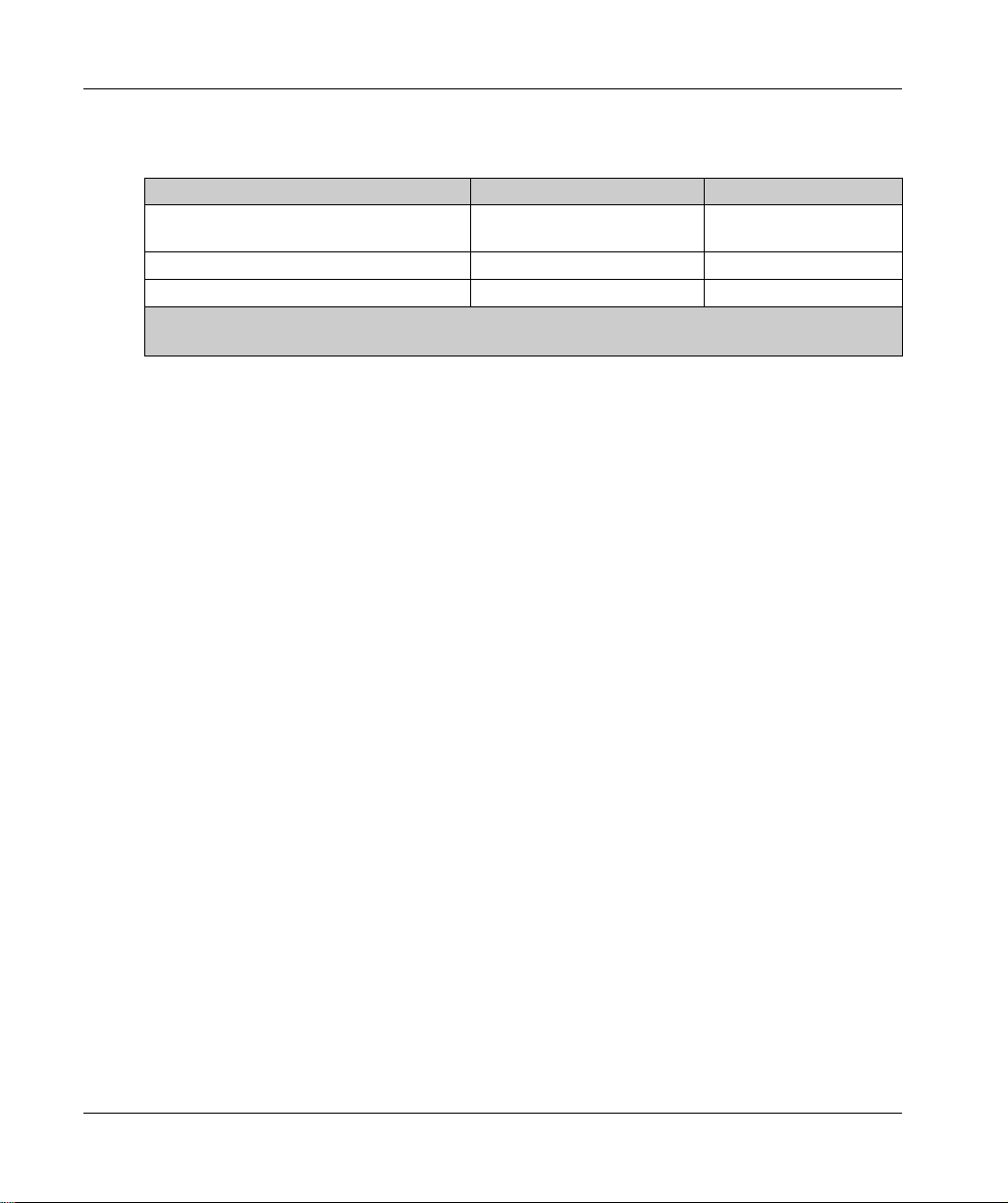
This table describes the different types of memory:
Memory Type Size Used
RAM 64 Mbytes, of which 8 Mbytes
Flash 128 Mbytes To save the program and data in case of a
18
(seepage48)
available for the application
(see page 44)
To execute the application.
power interruption.
.
EIO0000003101 12/2019
Page 19

Removable Storage
M251 Logic Controllers include an embedded SD card slot
The main uses of the SD card are:
Initializing the controller with a new application
Updating the controller firmware
Applying post configuration files to the controller
Applying recipes
Receiving data logging files
Embedded Communication Features
The M251 Logic Controller native communication ports include (depending on the controller
reference):
CANopen Master
Ethernet
USB Mini-B
Serial Line
(seepage101)
(see page 105)
(see page 106)
Expansion Module and Bus Coupler Compatibility
Refer to the compatibility tables in the EcoStruxure Machine Expert - Compatiblity and Migration
User Guide.
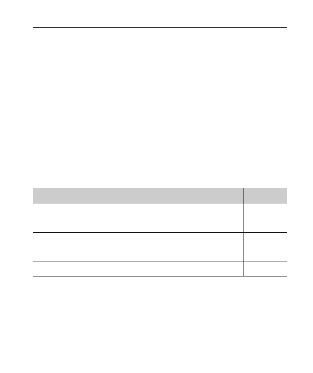
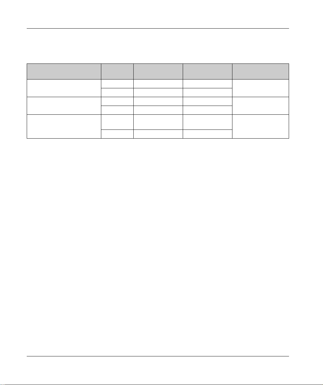
M251 Logic Controllers
(see page 49)
M251 General Overview
.
Reference Digital Inputs Digital Outputs Communication Ports
TM251MESC
(see page 87)
TM251MESE
(see page 91)
EIO0000003101 12/2019 19
0 0 1 serial line port
1 USB mini-B programming port
1 dual port Ethernet switch
1 CANopen port
0 0 1 serial line port
1 USB mini-B programming port
1 dual port Ethernet switch
1 Ethernet port for fieldbus
Page 20
M251 General Overview
Maximum Hardware Configuration
Introduction
The M251 Logic Controller is a control system that offers a scalable solution with optimized
configurations and an expandable architecture.
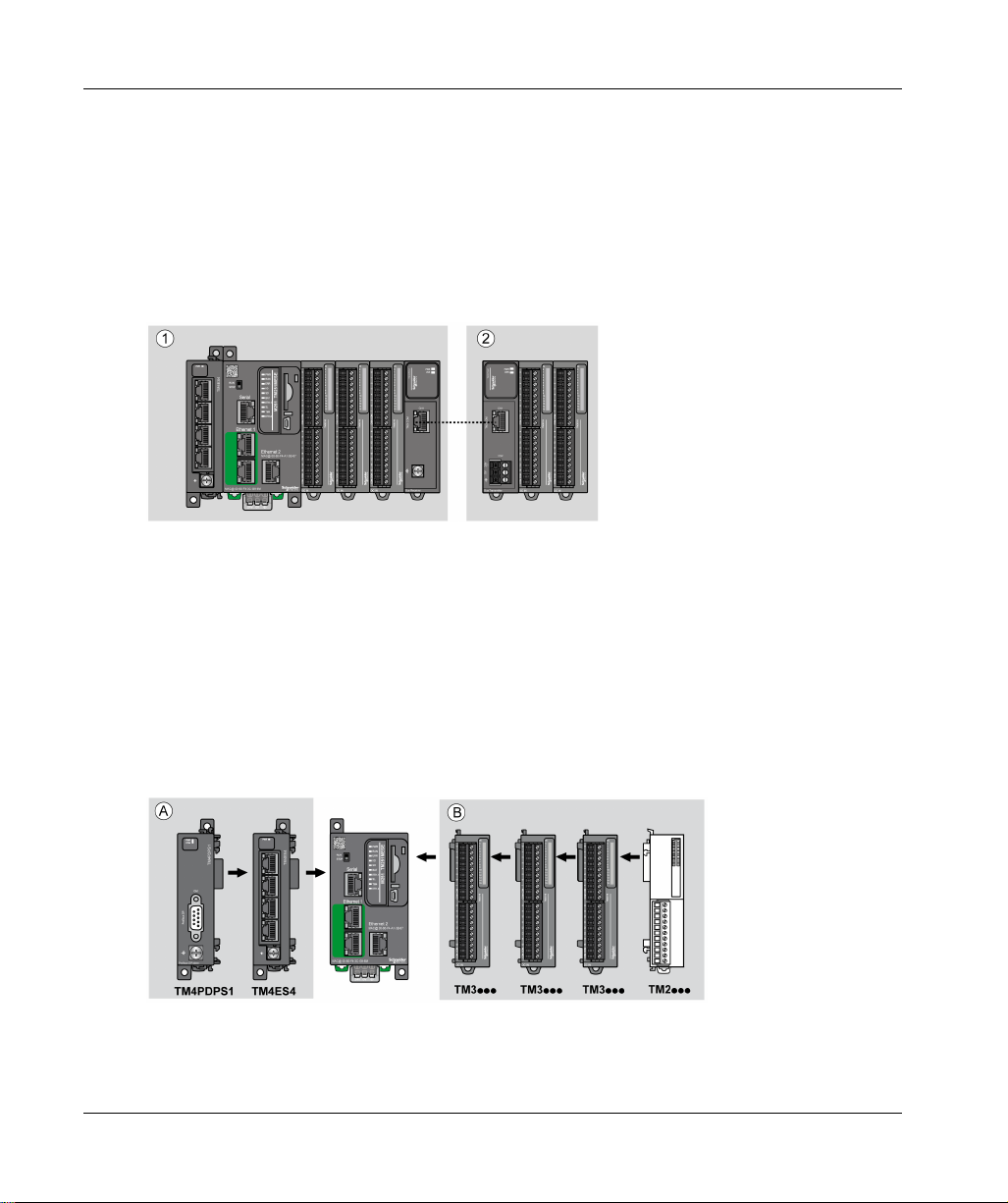
Local and Remote Configuration Principle
The following figure defines the local and remote configurations:
(1) Local configuration
(2) Remote configuration
M251 Logic Controller Local Configuration Architecture
Optimized local configuration and flexibility are provided by the association of:
M251 Logic Controller
TM4 expansion modules
TM3 expansion modules
TM2 expansion modules
Application requirements determine the architecture of your M251 Logic Controller configuration.
The following figure represents the components of a local configuration:
20
(A) Expansion modules (3 maximum)
(B) Expansion modules (7 maximum)
EIO0000003101 12/2019
Page 21
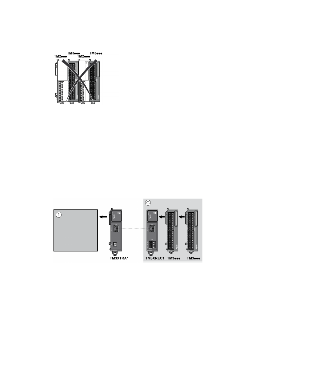
NOTE: It is prohibited to mount a TM2 module before any TM3 module as indicated in the following
figure:
M251 Logic Controller Remote Configuration Architecture
Optimized remote configuration and flexibility are provided by the association of:
M251 Logic Controller
TM4 expansion modules
TM3 expansion modules
TM3 transmitter and receiver modules
Application requirements determine the architecture of your M251 Logic Controller configuration.
NOTE: You cannot use TM2 modules in configurations that include the TM3 transmitter and
receiver modules.
The following figure represents the components of a remote configuration:
M251 General Overview
(1) Logic controller and modules
(C) TM3 expansion modules (7 maximum)
EIO0000003101 12/2019 21
Page 22
M251 General Overview
Maximum Number of Modules
The following table shows the maximum configuration supported:
References Maximum Type of Configuration
TM251•••• 7 TM3 / TM2 expansion
TM251•••• 3 TM4 expansion modules Local
TM3XREC1 7 TM3 expansion modules Remote
NOTE: TM3 transmitter and receiver modules are not included in a count of the maximum number of
expansion modules.
NOTE: The configuration with its TM4, TM3, and TM2 expansion modules is validated by
EcoStruxure Machine Expert software in the Configuration window.
NOTE: In some environments, the maximum configuration populated by high consumption
modules, coupled with the maximum distance allowable between the TM3 transmitter and receiver
modules, may present bus communication issues although the EcoStruxure Machine Expert
software allows for the configuration. In such a case you will need to analyze the power
consumption of the modules chosen for your configuration, as well as the minimum cable distance
required by your application, and possibly seek to optimize your choices.
Local
modules
22
EIO0000003101 12/2019
Page 23
TM2 Expansion Modules
Overview
You can expand the number of I/Os of your M251 Logic Controller by adding TM2 I/O expansion
modules.
The following types of electronic modules are supported:
TM2 digital I/O expansion modules
TM2 analog I/O expansion modules
For more information, refer to the following documents:
TM2 Digital I/O Expansion Modules Hardware Guide
TM2 Analog I/O Expansion Modules Hardware Guide
NOTE: TM2 modules can only be used in the local configuration, and only if there is no TM3
transmitter and receiver modules present in the configuration.
NOTE: It is prohibited to mount a TM2 module before any TM3 module. The TM2 modules must
be mounted and configured at the end of the local configuration.
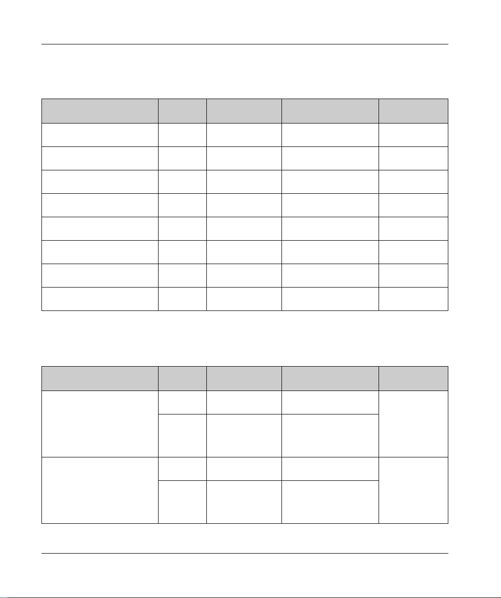
TM2 Digital Input Expansion Modules
The following table shows the compatible TM2 digital input expansion modules with the
corresponding channel type, nominal voltage/current, and terminal type:
M251 General Overview
Reference Channels Channel Type Voltage
Current
TM2DAI8DT 8 Regular inputs 120 Vac
7.5 mA
TM2DDI8DT 8 Regular inputs 24 Vdc
7mA
TM2DDI16DT 16 Regular inputs 24 Vdc
7mA
TM2DDI16DK 16 Regular inputs 24 Vdc
5mA
TM2DDI32DK 32 Regular inputs 24 Vdc
5mA
EIO0000003101 12/2019 23
Terminal Type
Removable screw
terminal block
Removable screw
terminal block
Removable screw
terminal block
HE10 (MIL 20)
connector
HE10 (MIL 20)
connector
Page 24
M251 General Overview
TM2 Digital Output Expansion Modules
The following table shows the compatible TM2 digital output expansion modules with the
corresponding channel type, nominal voltage/current, and terminal type:
Reference Channels Channel type Voltage
Current
TM2DRA8RT 8 Relay outputs 30 Vdc / 240 Vac
TM2DRA16RT 16 Relay outputs 30 Vdc / 240 Vac
TM2DDO8UT 8 Regular transistor
outputs (sink)
TM2DDO8TT 8 Regular transistor
outputs (source)
TM2DDO16UK 16 Regular transistor
outputs (sink)
TM2DDO16TK 16 Regular transistor
outputs (source)
TM2DDO32UK 32 Regular transistor
outputs (sink)
TM2DDO32TK 32 Regular transistor
outputs (source)
2 A max
2 A max
24 Vdc
0.3 A max per output
24 Vdc
0.5 A max per output
24 Vdc
0.1 A max per output
24 Vdc
0.4 A max per output
24 Vdc
0.1 A max per output
24 Vdc
0.4 A max per output
TM2 Digital Mixed Input/Output Expansion Modules
The following table shows the compatible TM2 digital mixed I/O expansion modules with the
corresponding channel type, nominal voltage/current, and terminal type:
Reference Channels Channel type Voltage
Current
TM2DMM8DRT 4 Regular inputs 24 Vdc
7mA
4 Relay outputs 24 Vdc / 240 Vac
TM2DMM24DRF 16 Regular inputs 24 Vdc
8 Relay outputs 24 Vdc / 240 Vac
7 A maximum per
common line / 2 A
maximum per output
7 mA
7 A maximum per
common line / 2 A
maximum per output
Terminal type
Removable screw
terminal block
Removable screw
terminal block
Removable screw
terminal block
Removable screw
terminal block
HE10 (MIL 20)
connector
HE10 (MIL 20)
connector
HE10 (MIL 20)
connector
HE10 (MIL 20)
connector
Terminal type
Removable screw
terminal block
Non-removable
spring terminal
block
24
EIO0000003101 12/2019
Page 25
TM2 Analog Input Expansion Modules
The following table shows the compatible TM2 analog input expansion modules with the
corresponding channel type, nominal voltage/current, and terminal type:
M251 General Overview
Reference Channels Channel type Voltage
Current
TM2AMI2HT 2 High-level inputs 0...10 Vdc
4...20 mA
TM2AMI2LT 2 Low-level inputs Thermocouple type
J,K,T
TM2AMI4LT 4 Analog inputs 0...10 Vdc
0...20 mA
PT100/1000
Ni100/1000
TM2AMI8HT 8 Analog inputs 0...20 mA
0...10 Vdc
TM2ARI8HT 8 Analog inputs NTC / PTC Removable screw
TM2ARI8LRJ 8 Analog inputs PT100/1000 RJ11 connector
TM2ARI8LT 8 Analog inputs PT100/1000 Removable screw
Terminal Type
Removable screw
terminal block
Removable screw
terminal block
Removable screw
terminal block
Removable screw
terminal block
terminal block
terminal block
TM2 Analog Output Expansion Modules
The following table shows the compatible TM2 analog output expansion modules with the
corresponding channel type, nominal voltage/current, and terminal type:
Reference Channels Channel type Voltage
Current
TM2AMO1HT 1 Analog outputs 0...10 Vdc
4...20 mA
TM2AVO2HT 2 Analog outputs +/- 10 Vdc Removable screw
Terminal Type
Removable screw
terminal block
terminal block
EIO0000003101 12/2019 25
Page 26
M251 General Overview
TM2 Analog Mixed Input/Output Expansion Modules
The following table shows the compatible TM2 analog mixed I/O expansion modules with the
corresponding channel type, nominal voltage/current, and terminal type:
Reference Channels Channel type Voltage
Current
TM2AMM3HT 2 Analog inputs 0...10 Vdc 4...20 mA Removable screw
1 Analog outputs 0...10 Vdc 4...20 mA
TM2AMM6HT 4 Analog inputs 0...10 Vdc 4...20 mA Removable screw
2 Analog outputs 0...10 Vdc 4...20 mA
TM2ALM3LT 2 Low-level inputs Thermo J,K,T,
PT100
1 Analog outputs 0...10 Vdc 4...20 mA
Terminal Type
terminal block
terminal block
Removable screw
terminal block
26
EIO0000003101 12/2019
Page 27

TM3 Expansion Modules
Introduction
The range of TM3 expansion modules includes:
Digital modules, classified as follows:
Input modules
Output modules
Mixed input/output modules
Analog modules, classified as follows:
Input modules
Output modules
Mixed input/output modules
Expert modules
Safety modules
Transmitter and Receiver modules
For more information, refer to the following documents:
TM3 Digital I/O Modules Hardware Guide
TM3 Analog I/O Modules Hardware Guide
TM3 Expert I/O Modules Hardware Guide
TM3 Safety Modules Hardware Guide
TM3 Transmitter and Receiver Modules Hardware Guide
(see page 27)
(see page 31)
(see page 34)
(see page 34)
M251 General Overview
(see page 28)
(see page 30)
(see page 32)
(see page 33)
(seepage35)
TM3 Digital Input Modules
The following table shows the TM3 digital input expansion modules, with corresponding channel
type, nominal voltage/current, and terminal type:
Reference Channels Channel Type Voltage
Current
TM3DI8A 8 Regular inputs 120 Vac
7.5 mA
TM3DI8 8 Regular inputs 24 Vdc
7mA
TM3DI8G 8 Regular inputs 24 Vdc
7mA
TM3DI16 16 Regular inputs 24 Vdc
7mA
EIO0000003101 12/2019 27
Terminal Type / Pitch
Removable screw
terminal block /
5.08 mm
Removable screw
terminal block /
5.08 mm
Removable spring
terminal block /
5.08 mm
Removable screw
terminal blocks /
3.81 mm
Page 28

M251 General Overview
Reference Channels Channel Type Voltage
Current
TM3DI16G 16 Regular inputs 24 Vdc
7mA
TM3DI16K 16 Regular inputs 24 Vdc
5mA
TM3DI32K 32 Regular inputs 24 Vdc
5mA
TM3 Digital Output Modules
The following table shows the TM3 digital output expansion modules, with corresponding channel
type, nominal voltage/current, and terminal type:
Reference Channels Channel Type Voltage
Current
TM3DQ8R 8 Relay outputs 24 Vdc / 240 Vac
7 A maximum per
common line / 2 A
maximum per output
TM3DQ8RG 8 Relay outputs 24 Vdc / 240 Vac
TM3DQ8T 8 Regular transistor
outputs (source)
TM3DQ8TG 8 Regular transistor
outputs (source)
TM3DQ8U 8 Regular transistor
outputs (sink)
TM3DQ8UG 8 Regular transistor
outputs (sink)
TM3DQ16R 16 Relay outputs 24 Vdc / 240 Vac
7 A maximum per
common line / 2 A
maximum per output
24 Vdc
4 A maximum per
common line/0.5 A
maximum per output
24 Vdc
4 A maximum per
common line/0.5 A
maximum per output
24 Vdc
4 A maximum per
common line/0.5 A
maximum per output
24 Vdc
4 A maximum per
common line/0.5 A
maximum per output
8 A maximum per
common line / 2 A
maximum per output
Terminal Type / Pitch
Removable spring
terminal blocks /
3.81 mm
HE10 (MIL 20)
connector
HE10 (MIL 20)
connector
Terminal Type / Pitch
Removable screw
terminal block /
5.08 mm
Removable spring
terminal block /
5.08 mm
Removable screw
terminal block /
5.08 mm
Removable spring
terminal block /
5.08 mm
Removable screw
terminal block /
5.08 mm
Removable spring
terminal block /
5.08 mm
Removable screw
terminal blocks /
3.81 mm
28
EIO0000003101 12/2019
Page 29

M251 General Overview
Reference Channels Channel Type Voltage
Current
TM3DQ16RG 16 Relay outputs 24 Vdc / 240 Vac
8 A maximum per
common line / 2 A
maximum per output
TM3DQ16T 16 Regular transistor
outputs (source)
24 Vdc
8 A maximum per
common line / 0.5 A
maximum per output
TM3DQ16TG 16 Regular transistor
outputs (source)
24 Vdc
8 A maximum per
common line / 0.5 A
maximum per output
TM3DQ16U 16 Regular transistor
outputs (sink)
24 Vdc
8 A maximum per
common line / 0.5 A
maximum per output
TM3DQ16UG 16 Regular transistor
outputs (sink)
24 Vdc
8 A maximum per
common line / 0.5 A
maximum per output
TM3DQ16TK 16 Regular transistor
outputs (source)
24 Vdc
2 A maximum per
common line / 0.1 A
maximum per output
TM3DQ16UK 16 Regular transistor
outputs (sink)
24 Vdc
2 A maximum per
common line / 0.1 A
maximum per output
TM3DQ32TK 32 Regular transistor
outputs (source)
24 Vdc
2 A maximum per
common line / 0.1 A
maximum per output
TM3DQ32UK 32 Regular transistor
outputs (sink)
24 Vdc
2 A maximum per
common line / 0.1 A
maximum per output
Terminal Type / Pitch
Removable spring
terminal blocks /
3.81 mm
Removable screw
terminal blocks /
3.81 mm
Removable spring
terminal blocks /
3.81 mm
Removable screw
terminal blocks /
3.81 mm
Removable spring
terminal blocks /
3.81 mm
HE10 (MIL 20)
connector
HE10 (MIL 20)
connector
HE10 (MIL 20)
connectors
HE10 (MIL 20)
connectors
EIO0000003101 12/2019 29
Page 30
M251 General Overview
TM3 Digital Mixed Input/Output Modules
This following table shows the TM3 mixed I/O modules, with corresponding channel type, nominal
voltage/current, and terminal type:
Reference Channels Channel Type Voltage
Current
TM3DM8R 4 Regular inputs 24 Vdc
7mA
4 Relay outputs 24 Vdc / 240 Vac
7 A maximum per
common line / 2 A
maximum per output
TM3DM8RG 4 Regular inputs 24 Vdc
7mA
4 Relay outputs 24 Vdc / 240 Vac
7 A maximum per
common line / 2 A
maximum per output
TM3DM24R 16 Regular inputs 24 Vdc
7mA
8 Relay outputs 24 Vdc / 240 Vac
7 A maximum per
common line / 2 A
maximum per output
TM3DM24RG 16 Regular inputs 24 Vdc
7mA
8 Relay outputs 24 Vdc / 240 Vac
7 A maximum per
common line / 2 A
maximum per output
Terminal Type / Pitch
Removable screw
terminal block /
5.08 mm
Removable spring
terminal block /5.08 mm
Removable screw
terminal
blocks / 3.81 mm
Removable spring
terminal
blocks / 3.81 mm
30
EIO0000003101 12/2019
Page 31

TM3 Analog Input Modules
The following table shows the TM3 analog input expansion modules, with corresponding
resolution, channel type, nominal voltage/current, and terminal type:
M251 General Overview
Reference Resolution Channels Channel
Type
TM3AI2H 16 bit, or
15 bit + sign
TM3AI2HG 16 bit, or
15 bit + sign
TM3AI4 12 bit, or
11 bit + sign
TM3AI4G 12 bit, or
11 bit + sign
TM3AI8 12 bit, or
11 bit + sign
TM3AI8G 12 bit, or
11 bit + sign
TM3TI4 16 bit, or
15 bit + sign
2 inputs 0...10 Vdc
2 inputs 0...10 Vdc
4 inputs 0...10 Vdc
4 inputs 0...10 Vdc
8 inputs 0...10 Vdc
8 inputs 0...10 Vdc
4 inputs 0...10 Vdc
Mode Terminal Type /
Pitch
Removable screw
-10…+10 Vdc
0...20 mA
4...20 mA
-10…+10 Vdc
0...20 mA
4...20 mA
-10…+10 Vdc
0...20 mA
4...20 mA
-10…+10 Vdc
0...20 mA
4...20 mA
-10…+10 Vdc
0...20 mA
4...20 mA
0...20 mA extended
4...20 mA extended
-10…+10 Vdc
0...20 mA
4...20 mA
0...20 mA extended
4...20 mA extended
-10…+10 Vdc
0...20 mA
4...20 mA
Thermocouple
PT100/1000
NI100/1000
terminal block /
5.08 mm
Removable spring
terminal block /
5.08 mm
Removable screw
terminal block /
3.81 mm
Removable spring
terminal blocks /
3.81 mm
Removable screw
terminal block /
3.81 mm
Removable spring
terminal blocks /
3.81 mm
Removable screw
terminal block /
3.81 mm
EIO0000003101 12/2019 31
Page 32

M251 General Overview
Reference Resolution Channels Channel
Type
TM3TI4G 16 bit, or
15 bit + sign
TM3TI4D 16 bit, or
15 bit + sign
TM3TI4DG 16 bit, or
15 bit + sign
TM3TI8T 16 bit, or
15 bit + sign
TM3TI8TG 16 bit, or
15 bit + sign
4 inputs 0...10 Vdc
4 inputs Thermocouple Removable screw
4 inputs Thermocouple Removable spring
8 inputs Thermocouple
8 inputs Thermocouple
TM3 Analog Output Modules
The following table shows the TM3 analog output modules, with corresponding resolution, channel
type, nominal voltage/current, and terminal type:
Mode Terminal Type /
Pitch
Removable spring
-10…+10 Vdc
0...20 mA
4...20 mA
Thermocouple
PT100/1000
NI100/1000
NTC/PTC
Ohmmeter
NTC/PTC
Ohmmeter
terminal blocks /
3.81 mm
terminal block /
3.81 mm
terminal blocks /
3.81 mm
Removable screw
terminal block /
3.81 mm
Removable spring
terminal blocks /
3.81 mm
Reference Resolution Channels Channel
Type
TM3AQ2 12 bit, or
11 bit + sign
TM3AQ2G 12 bit, or
11 bit + sign
TM3AQ4 12 bit, or
11 bit + sign
TM3AQ4G 12 bit, or
11 bit + sign
32
2 outputs 0...10 Vdc
2 outputs 0...10 Vdc
4 outputs 0...10 Vdc
4 outputs 0...10 Vdc
Mode Terminal Type / Pitch
Removable screw
-10…+10 Vdc
0...20 mA
4...20 mA
-10…+10 Vdc
0...20 mA
4...20 mA
-10…+10 Vdc
0...20 mA
4...20 mA
-10…+10 Vdc
0...20 mA
4...20 mA
terminal block /
5.08 mm
Removable spring
terminal block /
5.08 mm
Removable screw
terminal block /
5.08 mm
Removable spring
terminal block /
5.08 mm
EIO0000003101 12/2019
Page 33

TM3 Analog Mixed Input/Output Modules
This following table shows the TM3 analog mixed I/O modules, with corresponding resolution,
channel type, nominal voltage/current, and terminal type:
M251 General Overview
Reference Resolution Channels Channel
Type
TM3AM6 12 bit, or
11 bit + sign
TM3AM6G 12 bit, or
11 bit + sign
TM3TM3 16 bit, or
15 bit + sign
12 bit, or
11 bit + sign
TM3TM3G 16 bit, or
15 bit + sign
12 bit, or
11 bit + sign
4 inputs 0...10 Vdc
2 outputs
4 inputs 0...10 Vdc
2 outputs
2 inputs 0...10 Vdc
1 outputs 0...10 Vdc
2 inputs 0...10 Vdc
1 outputs 0...10 Vdc
Mode Terminal Type / Pitch
Removable screw
-10...+10 Vdc
0...20 mA
4...20 mA
-10...+10 Vdc
0...20 mA
4...20 mA
-10...+10 Vdc
0...20 mA
4...20 mA
Thermocouple
PT100/1000
NI100/1000
-10...+10 Vdc
0...20 mA
4...20 mA
-10...+10 Vdc
0...20 mA
4...20 mA
Thermocouple
PT100/1000
NI100/1000
-10...+10 Vdc
0...20 mA
4...20 mA
terminal block /
3.81 mm
Removable spring
terminal block /
3.81 mm
Removable screw
terminal block /
5.08 mm
Removable spring
terminal block /
5.08 mm
EIO0000003101 12/2019 33
Page 34

M251 General Overview
TM3 Expert Modules
The following table shows the TM3 expert expansion modules, with corresponding terminal types:
Reference Description Terminal Type / Pitch
TM3XTYS4
(see Modicon TM3,
Expert I/O Modules,
Hardware Guide)
TM3XHSC202
(see Modicon TM3,
Expert I/O Modules,
Hardware Guide)
TM3XHSC202G
(see Modicon TM3,
Expert I/O Modules,
Hardware Guide)
TM3 Safety Modules
This table contains the TM3 safety modules, with the corresponding channel type, nominal
voltage/current, and terminal type:
TeSys module 4 front connectors RJ-45
1 removable power supply
connector / 5.08 mm
High Speed Counting (HSC) module Removable screw terminal
blocks / 3.81 mm
High Speed Counting (HSC) module Removable spring terminal
blocks / 3.81 mm
Reference Function
Category
TM3SAC5R 1 function,
up to
category 3
TM3SAC5RG 1 function,
up to
category 3
TM3SAF5R 1 function,
up to
category 4
(1)
Depending on external wiring
(2)
Non-monitored start
34
Channels Channel type Voltage
Current
(1)
1 or 2
(2)
Start
3 in parallel Relay outputs
(1)
1 or 2
(2)
Start
3 in parallel Relay outputs
(1)
2
Start Input
3 in parallel Relay outputs
Safety input 24 Vdc
Input
100 mA maximum
24 Vdc / 230 Vac
Normally open
6 A maximum per output
Safety input 24 Vdc
Input
100 mA maximum
24 Vdc / 230 Vac
Normally open
6 A maximum per output
Safety inputs 24 Vdc
100 mA maximum
24 Vdc / 230 Vac
Normally open
6 A maximum per output
Terminal type
3.81 mm (0.15 in.) and
5.08 mm (0.20 in.),
removable screw
terminal block
3.81 mm (0.15 in.) and
5.08 mm (0.20 in.),
removable spring
terminal block
3.81 mm (0.15 in.) and
5.08 mm (0.20 in.),
removable screw
terminal block
EIO0000003101 12/2019
Page 35

M251 General Overview
Reference Function
Category
TM3SAF5RG 1 function,
up to
category 4
TM3SAFL5R 2 functions,
up to
category 3
TM3SAFL5RG 2 functions,
up to
category 3
TM3SAK6R 3 functions,
up to
category 4
TM3SAK6RG 3 functions,
up to
category 4
(1)
Depending on external wiring
(2)
Non-monitored start
Channels Channel type Voltage
Current
(1)
2
Start Input
3 in parallel Relay outputs
(1)
2
Start Input
3 in parallel Relay outputs
(1)
2
Start Input
3 in parallel Relay outputs
(1)
1 or 2
Start Input
3 in parallel Relay outputs
(1)
1 or 2
Start Input
3 in parallel Relay outputs
Safety inputs 24 Vdc
100 mA maximum
24 Vdc / 230 Vac
Normally open
6 A maximum per output
Safety inputs 24 Vdc
100 mA maximum
24 Vdc / 230 Vac
Normally open
6 A maximum per output
Safety inputs 24 Vdc
100 mA maximum
24 Vdc / 230 Vac
Normally open
6 A maximum per output
Safety inputs 24 Vdc
100 mA maximum
24 Vdc / 230 Vac
Normally open
6 A maximum per output
Safety inputs 24 Vdc
100 mA maximum
24 Vdc / 230 Vac
Normally open
6 A maximum per output
Terminal type
3.81 mm (0.15 in.) and
5.08 mm (0.20 in.),
removable spring
terminal block
3.81 mm (0.15 in.) and
5.08 mm (0.20 in.),
removable screw
terminal block
3.81 mm (0.15 in.) and
5.08 mm (0.20 in.),
removable spring
terminal block
3.81 mm (0.15 in.) and
5.08 mm (0.20 in.),
removable screw
terminal block
3.81 mm (0.15 in.) and
5.08 mm (0.20 in.),
removable spring
terminal block
TM3 Transmitter and Receiver Modules
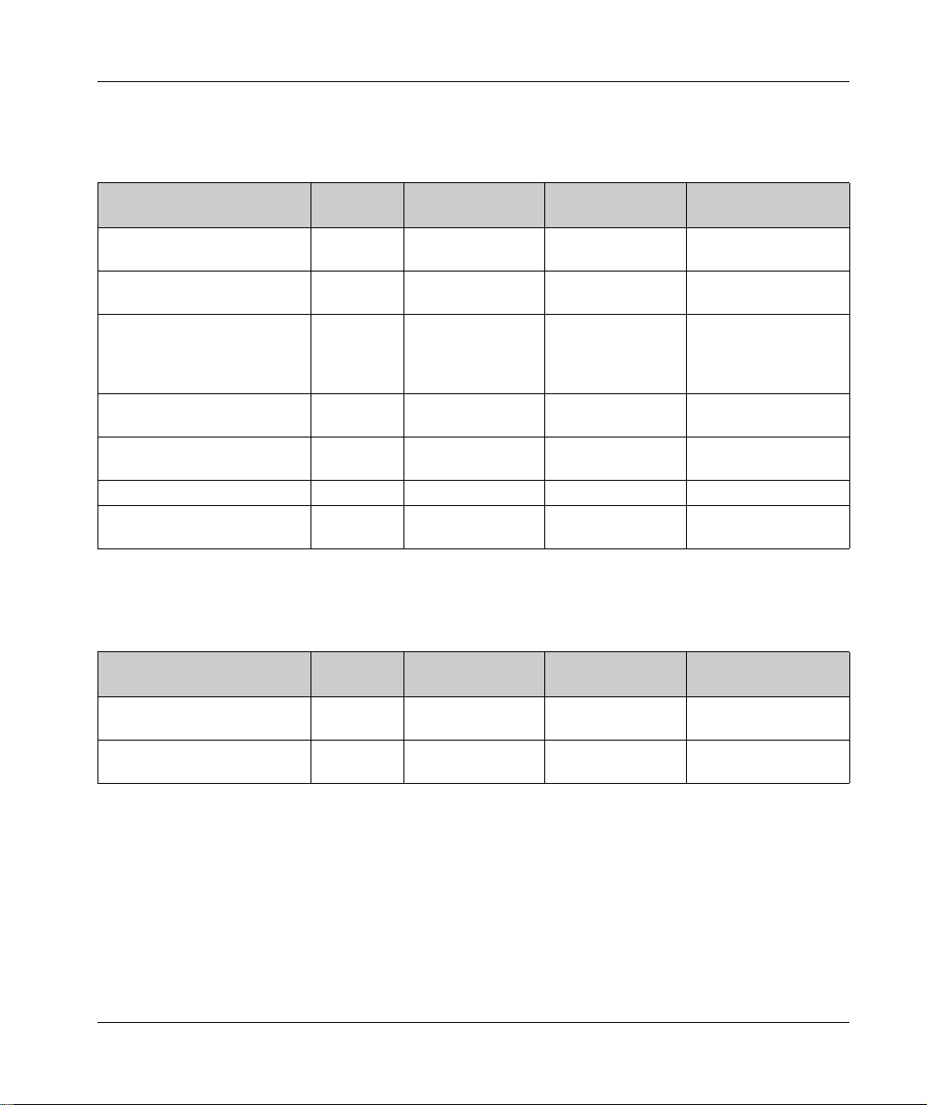
The following table shows the TM3 transmitter and receiver expansion modules:
Reference Description Terminal Type / Pitch
TM3XTRA1 Data transmitter module for remote I/O 1 front connector RJ-45
TM3XREC1 Data receiver module for remote I/O 1 front connector RJ-45
EIO0000003101 12/2019 35
1 screw for functional ground
connection
Power supply connector /
5.08 mm
Page 36

M251 General Overview
TM3 Bus Couplers
Introduction
The TM3 bus coupler is a device designed to manage fieldbus communication when using TM2
and TM3 expansion modules in a distributed architecture.
For more information, refer to the Modicon TM3 Bus Coupler Hardware Guide
Bus Coupler, Hardware Guide)
Modicon TM3 Bus Couplers
The following table shows the TM3 bus couplers, with ports and terminal types:
Reference Port Communication type Terminal type
TM3BCEIP 2 isolated switched
TM3BCSL 2 isolated ports Serial Line
(see Modicon TM3
.
Ethernet ports
1 USB mini-B port USB 2.0 USB mini-B
1 USB mini-B port USB 2.0 USB mini-B
EtherNet/IP
Modbus TCP
Modbus
RJ45
RJ45
36
EIO0000003101 12/2019
Page 37

TM4 Expansion Modules
Introduction
The range of TM4 expansion modules includes communication modules.
For more information, refer to the TM4 Expansion Modules Hardware Guide.
TM4 Expansion Modules
The following table shows the TM4 expansion module features:
Module reference Type Terminal type
TM4ES4 Ethernet communication 4 RJ45 connectors
TM4PDPS1 PROFIBUS DP slave communication 1 SUB-D 9 pins female connector
NOTE: The TM4ES4 module has two applications: expansion or standalone. For more information, refer to
TM4 Compatibility.
M251 General Overview
1 screw for functional ground connection
1 screw for functional ground connection
EIO0000003101 12/2019 37
Page 38

M251 General Overview
TM5 Fieldbus Interfaces
Introduction
The TM5 fieldbus interfaces are devices designed to manage EtherNet/IP communication when
using TM5 System and TM7 expansion modules with a controller in a distributed architecture.
For more information, refer to the Modicon TM5 System Interface – Hardware Guide.
TM5 Fieldbus Interfaces
The following table shows the TM5 fieldbus interfaces with ports and terminal type:
Reference Port Communication type Terminal type
TM5NEIP1 2 Ethernet switched ports EtherNet/IP RJ45
38
EIO0000003101 12/2019
Page 39

TM5 CANopen Fieldbus Interfaces
Introduction
The TM5 fieldbus module is a CANopen interface with built-in power distribution and is the first
TM5 distributed I/O island.
For more information, refer to the Modicon TM5 CANopen Interface Hardware Guide.
Modicon TM5 CANopen Fieldbus Interfaces
The following table shows the TM5 CANopen fieldbus interfaces:
Reference Communication type Terminal type
TM5NCO1 CANopen 1 SUB-D 9, male
M251 General Overview
EIO0000003101 12/2019 39
Page 40

M251 General Overview
TM7 CANopen Fieldbus Interfaces
Introduction
The TM7 fieldbus modules are CANopen interfaces with 24 Vdc digital configurable input or output
on 8 or 16 channels.
For more information, refer to the Modicon TM7 CANopen Interface I/O Blocks Hardware Guide.
Modicon TM7 CANopen Fieldbus Interfaces
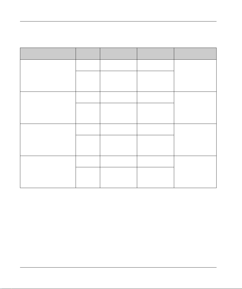
The following table shows the TM7 CANopen fieldbus interfaces:
Reference Number of channels Voltage/Current Communication type Terminal type
TM7NCOM08B 8 inputs
8 outputs
TM7NCOM16A 16 inputs
16 outputs
TM7NCOM16B 16 inputs
16 outputs
24 Vdc / 4 mA
24 Vdc / 500 mA
24 Vdc / 4 mA
24 Vdc / 500 mA
24 Vdc / 4 mA
24 Vdc / 500 mA
CANopen M8 Connector
CANopen M8 Connector
CANopen M12 Connector
40
EIO0000003101 12/2019
Page 41

M251 General Overview
Accessories
Overview
This section describes the accessories and cables.
Accessories
Reference Description Use Quantity
TMASD1 SD Card
(see page 49)
TMAT2PSET Set of 5 removable
screw terminal block
NSYTRAAB35 End brackets Helps secure the controller or receiver module and
TM2XMTGB Grounding Bar Connects the cable shield and the module to the
TM200RSRCEMC Shielding take-up
clip
Use to update the controller firmware, initialize a
controller with a new application or clone a
controller, manage user files, etc.,.
Connects 24 Vdc power supply. 1
their expansion modules on a top hat section rail
(DIN rail).
functional ground.
Mounts and connects the ground to the cable
shielding.
Cables
1
1
1
25 pack
Reference Description Details Length
TCSXCNAMUM3P Terminal port/USB
port cordset
TCSMCN3M4F3C2 RS-232 serial link
cordset
1 RJ45 connector
and 1 SUB-D 9
connector
TCSMCN3M4M3S2 RS-232 serial link
cordset
1 RJ45 connector
and 1 SUB-D 9
connector
EIO0000003101 12/2019 41
From the USB mini-B port on the M251 Logic
Controller to USB port on the PC terminal.
For DTE terminal (printer). 3 m
For DCE terminal (modem, converter). 3 m
3m
(10 ft)
(9.84 ft)
(9.84 ft)
Page 42

M251 General Overview
Reference Description Details Length
490NTW000•• Ethernet shielded
cable for DTE
connections
Standard cable, equipped with RJ45
connectors at each end for DTE.
CE compliant.
490NTW000••U Standard cable, equipped with RJ45
connectors at each end for DTE.
UL compliant.
TCSECE3M3M••S4 Cable for harsh environment, equipped with
RJ45 connectors at each end.
CE compliant.
TCSECU3M3M••S4 Cable for harsh environment, equipped with
RJ45 connectors at each end.
UL compliant.
2, 5, 12, 40, or 80 m
(6.56, 16.4, 39.37,
131.23 or 262.47 ft)
2, 5, 12, 40, or 80 m
(6.56, 16.4, 39.37,
131.23, or 262.47 ft)
1, 2, 3, 5, or 10 m
(3.28, 6.56, 9.84, 16.4,
32.81 ft)
1, 2, 3, 5, or 10 m
(3.28, 6.56, 9.84, 16.4,
32.81 ft)
42
EIO0000003101 12/2019
Page 43

Modicon M251 Logic Con troller
M251 Features
EIO0000003101 12/2019
M251 Features
Chapter 2
M251 Features
Overview
This chapter describes the Modicon M251 Logic Controller features.
What Is in This Chapter?
This chapter contains the following topics:
Real Time Clock (RTC) 44
Run/Stop 48
SD Card 49
Topic Page
EIO0000003101 12/2019 43
Page 44

M251 Features
Real Time Clock (RTC)
Overview
The M251 Logic Controller includes an RTC to provide system date and time information, and to
support related functions requiring a real-time clock. To continue keeping time when power is off,
a non-rechargeable battery is required (see reference below). A battery LED on the front panel of
the controller indicates if the battery is depleted or absent.
This table shows how RTC drift is managed:
RTC Characteristics Description
RTC drift Less than 60 seconds per month without any user calibration at 25 °C
Battery
The controller has one battery.
In the event of a power interruption, the backup battery maintains the RTC for the controller.
This table shows the characteristics of the battery:
Characteristics Description
Use In the event of a transient power outage, the battery powers the RTC.
Backup life At least 2 years at 25 °C maximum (77 °F). At higher temperatures, the time
Battery monitoring Yes
Replaceable Yes
Controller battery type Lithium carbon monofluoride, type Panasonic BR2032
(77 °F)
is reduced.
44
EIO0000003101 12/2019
Page 45

Installing and Replacing the Battery
While lithium batteries are preferred due to their slow discharge and long life, they can present
hazards to personnel, equipment and the environment and must be handled properly.
EXPLOSION, FIRE, OR CHEMICAL BURNS
Replace with identical battery type.
Follow all the instructions of the battery manufacturer.
Remove all replaceable batteries before discarding unit.
Recycle or properly dispose of used batteries.
Protect battery from any potential short-circuit.
Do not recharge, disassemble, heat above 100 °C (212 °F), or incinerate.
Use your hands or insulated tools to remove or replace the battery.
Maintain proper polarity when inserting and connecting a new battery.
Failure to follow these instructions will result in death or serious injury.
To install or replace the battery, follow these steps:
Step Action
1 Remove power from your controller.
2 Use an insulated screw-driver to pull out the battery holder.
M251 Features
DANGER
3 Side out the battery holder of the controller
EIO0000003101 12/2019 45
Page 46

M251 Features
Step Action
4 Remove the battery from the battery holder.
5 Insert the new battery into the battery holder in accordance with the polarity markings on the
battery.
46
6 Replace the battery holder on the controller and verify that the latch clicks into place.
EIO0000003101 12/2019
Page 47

M251 Features
Step Action
7 Slide in the battery holder of the controller.
8 Power up your M251 Logic Controller.
9 Set the internal clock. For further details on the internal clock, refer to M251 Logic Controller
Programming Guide
(see Modicon M251 Logic Controller, Programming Guide)
.
NOTE: Replacement of the battery in the controllers other than with the type specified in this
documentation may present a risk of fire or explosion.
WARNING
IMPROPER BATTERY CAN PROVOKE FIRE OR EXPLOSION
Replace battery only with identical type: Panasonic Type BR2032.
Failure to follow these instructions can result in death, serious injury, or equipment damage.
EIO0000003101 12/2019 47
Page 48

M251 Features
Run/Stop
Run/Stop
The M251 Logic Controller can be operated externally by the following:
a hardware Run/Stop switch
an EcoStruxure Machine Expert software command.
The M251 Logic Controller has a Run/Stop hardware switch, which puts the controller in a RUN or
STOP state.
48
EIO0000003101 12/2019
Page 49

SD Card
Overview
When handling the SD card, follow the instructions below to help prevent internal data on the SD
card from being corrupted or lost or an SD card malfunction from occurring:
LOSS OF APPLICATION DATA
Do not store the SD card where there is static electricity or probable electromagnetic fields.
Do not store the SD card in direct sunlight, near a heater, or other locations where high
Do not bend the SD card.
Do not drop or strike the SD card against another object.
Keep the SD card dry.
Do not touch the SD card connectors.
Do not disassemble or modify the SD card.
Use only SD cards formatted using FAT or FAT32.
Failure to follow these instructions can result in equipment damage.
The M251 Logic Controller does not recognize NTFS formatted SD cards. Format the SD card on
your computer using FAT or FAT32.
When using the M251 Logic Controller and an SD card, observe the following to avoid losing
valuable data:
Accidental data loss can occur at any time. Once data is lost it cannot be recovered.
If you forcibly extract the SD card, data on the SD card may become corrupted.
Removing an SD card that is being accessed could damage the SD card, or corrupt its data.
If the SD card is not positioned correctly when inserted into the controller, the data on the card
M251 Features
NOTICE
temperatures can occur.
and the controller could become damaged.
NOTICE
LOSS OF APPLICATION DATA
Backup SD card data regularly.
Do not remove power or reset the controller, and do not insert or remove the SD card while it
is being accessed.
Failure to follow these instructions can result in equipment damage.
EIO0000003101 12/2019 49
Page 50

M251 Features
This figure shows the SD card slot:
It is possible to set the Write-Control Tab to prevent write operations to the SD card. Push the tab
up, as shown in the example on the right-hand side, to release the lock and enable writing to the
SD card. Before using an SD card, read the manufacturer's instructions.
50
EIO0000003101 12/2019
Page 51

Step Action
1 Insert the SD card into the SD card slot:
2 Push until you hear it “click”:
M251 Features
SD Card Slot Characteristics
Topic Characteristics Description
Supported type Standard Capacity SD (SDSC)
High Capacity SDHC
Global memory Size 16 GB max.
EIO0000003101 12/2019 51
Page 52

M251 Features
TMASD1 Characteristics
Characteristics Description
Card removal durability Minimum 1000 times
File retention time 10 years @ 25 °C (77 °F)
Flash type SLC NAND
Memory size 256 MB
Ambient operation temperature –10 … +85°C (14...185 °F)
Storage temperature –25 … +85°C (–13...185 °F)
Relative humidity 95% max. non-condensing
Write/Erase cycles 3,000,000 (approximately)
NOTE: The TMASD1 has been rigorously tested in association with the logic controller. For other
commercially available cards, consult your local sales representative.
NOTE: The SD card can be used directly on your PC.
52
EIO0000003101 12/2019
Page 53

Modicon M251 Logic Con troller
M251 Installation
EIO0000003101 12/2019
M251 Installation
Chapter 3
M251 Installation
Overview
This chapter provides installation safety guidelines, device dimensions, mounting instructions, and
environmental specifications.
What Is in This Chapter?
This chapter contains the following sections:
Section Topic Page
3.1 M251 Logic Controller General Rules for Implementing 54
3.2 M251 Logic Controller Installation 59
3.3 M251 Electrical Requirements 74
EIO0000003101 12/2019 53
Page 54

M251 Installation
M251 Logic Controller G eneral Rules for Implementing
Section 3.1
M251 Logic Controller General Rules for Implementing
What Is in This Section?
This section contains the following topics:
Environmental Characteristics 55
Certifications and Standards 58
Topic Page
54
EIO0000003101 12/2019
Page 55

Environmental Characteristics
Enclosure Requirements
M251 Logic Controller system components are designed as Zone B, Class A industrial equipment
according to IEC/CISPR Publication 11. If they are used in environments other than those
described in the standard, or in environments that do not meet the specifications in this manual,
the ability to meet electromagnetic compatibility requirements in the presence of conducted and/or
radiated interference may be reduced.
All M251 Logic Controller system components meet European Community (CE) requirements for
open equipment as defined by IEC/EN 61131-2. You must install them in an enclosure designed
for the specific environmental conditions and to minimize the possibility of unintended contact with
hazardous voltages. Use metal enclosures to improve the electromagnetic immunity of your M251
Logic Controller system. Use enclosures with a keyed locking mechanism to minimize
unauthorized access.
Environmental Characteristics
All the M251 Logic Controller module components are electrically isolated between the internal
electronic circuit and the input/output channels within the limits set forth and described by these
environmental characteristics. For more information on electrical isolation, see the technical
specifications of your particular controller found later in the current document. This equipment
meets CE requirements as indicated in the table below. This equipment is intended for use in a
Pollution Degree 2 industrial environment.
M251 Installation
WARNING
UNINTENDED EQUIPMENT OPERATION
Do not exceed any of the rated values specified in the environmental and electrical characteristics
tables.
Failure to follow these instructions can result in death, serious injury, or equipment damage.
EIO0000003101 12/2019 55
Page 56

M251 Installation
The following table shows the general environmental characteristics:
Characteristic Minimum
Tested Range
Specification
Standard compliance IEC/EN 61131-2
–
IEC/EN 61010-2201
Ambient operating temperature – Horizontal
–10...55 °C (14...131 °F)
installation
– Vertical installation –10...35 °C (14...95 °F)
Storage temperature – –25...70 °C (- 13...158 °F)
Relative humidity – Transport and
10...95 % (non-condensing)
storage
Operation 10...95 % (non-condensing)
Degree of pollution IEC/EN 60664-1 2
Degree of protection IEC/EN 61131-2 IP20 with protective covers in place
Corrosion immunity – Atmosphere free from corrosive gases
Operating altitude – 0...2000 m (0...6560 ft)
Storage altitude – 0...3000 m (0...9843 ft)
Vibration resistance IEC/EN 61131-2 Panel mounting or
mounted on a top
hat section rail (DIN
rail)
3.5 mm (0.13 in) fixed amplitude
from 5...8.4 Hz
2
9.8 m/s
(32.15 ft/s2) (1 gn) fixed
acceleration from 8.4...150 Hz
10 mm (0.39 in) fixed amplitude
from 5...8.7 Hz
29.4 m/s
2
(96.45 ft/s2) (3 gn) fixed
acceleration from 8.7...150 Hz
Mechanical shock resistance –
147 m/s
2
or 482.28 ft/s2 (15 gn) for a duration of 11 ms
NOTE: The tested ranges may indicate values beyond that of the IEC Standard. However, our internal standards
define what is necessary for industrial environments. In all cases, we uphold the minimum specification if indicated.
56
EIO0000003101 12/2019
Page 57

Electromagnetic Susceptibility
The M251 Logic Controller system meets electromagnetic susceptibility specifications as indicated
in the following table:
Characteristic Minimum Specification Tested Range
Electrostatic discharge IEC/EN 61000-4-2 8 kV (air discharge)
4 kV (contact discharge)
Radiated electromagnetic
field
Fast transients burst IEC/EN 61000-4-4 24 Vdc main
Surge immunity IEC/EN 61000-4-5
Induced electromagnetic field IEC/EN 61000-4-6 10 Vrms (0.15...80 MHz)
Conducted emission IEC 61000-6-4
Radiated emission IEC 61000-6-4 30...230 MHz: 40 dBμV/m QP
1 Common Mode
2 Differential Mode
IEC/EN 61000-4-3 10 V/m (80...1000 MHz)
3 V/m (1.4...2 GHz)
1 V/m (2...3 GHz)
2kV (CM
power lines
24 Vdc I/Os 2 kV (clamp)
Relay output 1 kV (clamp)
Digital I/Os 1 kV (clamp)
Communication
1kV (clamp)
line
IEC/EN 61131-2
–
DC Power lines 0.5 kV 0.5 kV
CM
Relay Outputs – –
24 Vdc I/Os – –
Shielded cable
1kV –
(between shield
and ground)
10...150 kHz: 120...69 dBμV/m QP
150...1500 kHz: 79...63 dBμV/m QP
1.5...30 MHz: 63 dBμV/m QP
230...1000 MHz: 47 dBμV/m QP
1
1
and DM2)
M251 Installation
2
DM
NOTE: The tested ranges may indicate values beyond that of the IEC Standard. However, our internal standards
define what is necessary for industrial environments. In all cases, we uphold the minimum specification if indicated.
EIO0000003101 12/2019 57
Page 58

M251 Installation
Certifications and Standards
Introduction
The M251 Logic Controllers are designed to conform to the main national and international
standards concerning electronic industrial control devices:
IEC/EN 61131-2
UL 508
CSA 22.2 n° 142
CSA E61131-2
The M251 Logic Controllers have obtained the following conformity marks:
CE
cULus
CSA
For product compliance and environmental information (RoHS, REACH, PEP, EOLI, etc.), go to
www.schneider-electric.com/green-premium
.
58
EIO0000003101 12/2019
Page 59

M251 Logic Controller Installation
Section 3.2
M251 Logic Controller Installation
What Is in This Section?
This section contains the following topics:
Installation and Maintenance Requirements 60
M251 Logic Controller Mounting Positions and Clearances 63
Top Hat Section Rail (DIN rail) 66
Installing and Removing the Controller with Expansions 70
Direct Mounting on a Panel Surface 73
M251 Installation
Topic Page
EIO0000003101 12/2019 59
Page 60

M251 Installation
Installation and Maintenance Requirements
Before Starting
Read and understand this chapter before beginning the installation of your system.
The use and application of the information contained herein require expertise in the design and
programming of automated control systems. Only you, the user, machine builder or integrator, can
be aware of all the conditions and factors present during installation and setup, operation, and
maintenance of the machine or process, and can therefore determine the automation and
associated equipment and the related safeties and interlocks which can be effectively and properly
used. When selecting automation and control equipment, and any other related equipment or
software, for a particular application, you must also consider any applicable local, regional or
national standards and/or regulations.
Pay particular attention in conforming to any safety information, different electrical requirements,
and normative standards that would apply to your machine or process in the use of this equipment.
Disconnecting Power
All options and modules should be assembled and installed before installing the control system on
a mounting rail, onto a mounting plate or in a panel. Remove the control system from its mounting
rail, mounting plate or panel before disassembling the equipment.
HAZARD OF ELECTRIC SHOCK, EXPLOSION OR ARC FLASH
Disconnect all power from all equipment including connected devices prior to removing any
covers or doors, or installing or removing any accessories, hardware, cables, or wires except
under the specific conditions specified in the appropriate hardware guide for this equipment.
Always use a properly rated voltage sensing device to confirm the power is off where and when
indicated.
Replace and secure all covers, accessories, hardware, cables, and wires and confirm that a
proper ground connection exists before applying power to the unit.
Use only the specified voltage when operating this equipment and any associated products.
Failure to follow these instructions will result in death or serious injury.
DANGER
60
EIO0000003101 12/2019
Page 61

Programming Considerations
UNINTENDED EQUIPMENT OPERATION
Only use software approved by Schneider Electric for use with this equipment.
Update your application program every time you change the physical hardware configuration.
Failure to follow these instructions can result in death, serious injury, or equipment damage.
Operating Environment
In addition to the Environmental Characteristics, refer to Product Related Information in the
beginning of the present document for important information regarding installation in hazardous
locations for this specific equipment.
UNINTENDED EQUIPMENT OPERATION
Install and operate this equipment according to the conditions described in the Environmental
Characteristics.
Failure to follow these instructions can result in death, serious injury, or equipment damage.
M251 Installation
WARNING
WARNING
EIO0000003101 12/2019 61
Page 62

M251 Installation
Installation Considerations
UNINTENDED EQUIPMENT OPERATION
Use appropriate safety interlocks where personnel and/or equipment hazards exist.
Install and operate this equipment in an enclosure appropriately rated for its intended
environment and secured by a keyed or tooled locking mechanism.
Use the sensor and actuator power supplies only for supplying power to the sensors or
actuators connected to the module.
Power line and output circuits must be wired and fused in compliance with local and national
regulatory requirements for the rated current and voltage of the particular equipment.
Do not use this equipment in safety-critical machine functions unless the equipment is
otherwise designated as functional safety equipment and conforming to applicable regulations
and standards.
Do not disassemble, repair, or modify this equipment.
Do not connect any wiring to reserved, unused connections, or to connections designated as
No Connection (N.C.).
Failure to follow these instructions can result in death, serious injury, or equipment damage.
NOTE: JDYX2 or JDYX8 fuse types are UL-recognized and CSA approved.
WARNING
62
EIO0000003101 12/2019
Page 63

M251 Logic Controller Mounting Positions and Clearances
Introduction
This section describes the correct mounting positions for the M251 Logic Controller.
NOTE: Keep adequate spacing for proper ventilation and to maintain the operating temperature
specified in the Environmental Characteristics
Correct Mounting Position
To obtain optimal operating characteristics, the M251 Logic Controller should be mounted
horizontally on a vertical plane as shown in the figure below:
Acceptable Mounting Positions
The M251 Logic Controller can also be mounted vertically on a vertical plane as shown below.
(seepage55)
.
M251 Installation
NOTE: Expansion modules must be mounted above the controller.
EIO0000003101 12/2019 63
Page 64

M251 Installation
Incorrect Mounting Position
The M251 Logic Controller should only be positioned as shown in the Correct Mounting Position
figure. The figures below show the incorrect mounting positions.
Minimum Clearances
UNINTENDED EQUIPMENT OPERATION
Place devices dissipating the most heat at the top of the cabinet and ensure adequate
ventilation.
Avoid placing this equipment next to or above devices that might cause overheating.
Install the equipment in a location providing the minimum clearances from all adjacent
structures and equipment as directed in this document.
Install all equipment in accordance with the specifications in the related documentation.
Failure to follow these instructions can result in death, serious injury, or equipment damage.
WARNING
64
The M251 Logic Controller has been designed as an IP20 product and must be installed in an
enclosure. Clearances must be respected when installing the product.
There are 3 types of clearances to consider:
The M251 Logic Controller and all sides of the cabinet (including the panel door).
The M251 Logic Controller terminal blocks and the wiring ducts to help reduce potential
electromagnetic interference between the controller and the duct wiring.
The M251 Logic Controller and other heat generating devices installed in the same cabinet.
EIO0000003101 12/2019
Page 65

M251 Installation
The following figure shows the minimum clearances that apply to all M251 Logic Controller
references:
EIO0000003101 12/2019 65
Page 66

M251 Installation
Top Hat Section Rail (DIN rail)
Dimensions of Top Hat Section Rail DIN Rail
You can mount the controller or receiver and their expansions on a 35 mm (1.38 in.) top hat section
rail (DIN rail). The DIN rail can be attached to a smooth mounting surface or suspended from a EIA
rack or mounted in a NEMA cabinet.
Symmetric Top Hat Section Rails (DIN Rail)
The following illustration and table indicate the references of the top hat section rails (DIN rail) for
the wall-mounting range:
66
Reference Type Rail Length (B)
NSYSDR50A A 450 mm (17.71 in.)
NSYSDR60A A 550 mm (21.65 in.)
NSYSDR80A A 750 mm (29.52 in.)
NSYSDR100A A 950 mm (37.40 in.)
EIO0000003101 12/2019
Page 67

M251 Installation
The following illustration and table indicate the references of the symmetric top hat section rails
(DIN rail) for the metal enclosure range:
Reference Type Rail Length (B-12 mm)
NSYSDR60 A 588 mm (23.15 in.)
NSYSDR80 A 788 mm (31.02 in.)
NSYSDR100 A 988 mm (38.89 in.)
NSYSDR120 A 1188 mm (46.77 in.)
The following illustration and table indicate the references of the symmetric top hat section rails
(DIN rail) of 2000 mm (78.74 in.):
Reference Type Rail Length
NSYSDR200
NSYSDR200D
1
2
A 2000 mm (78.74 in.)
A
1 Unperforated galvanized steel
2 Perforated galvanized steel
EIO0000003101 12/2019 67
Page 68

M251 Installation
Double-Profile Top Hat Section Rails (DIN rail)
The following illustration and table indicate the references of the double-profile top hat section rails
(DIN rails) for the wall-mounting range:
Reference Type Rail Length (B)
NSYDPR25 W 250 mm (9.84 in.)
NSYDPR35 W 350 mm (13.77 in.)
NSYDPR45 W 450 mm (17.71 in.)
NSYDPR55 W 550 mm (21.65 in.)
NSYDPR65 W 650 mm (25.60 in.)
NSYDPR75 W 750 mm (29.52 in.)
68
EIO0000003101 12/2019
Page 69

M251 Installation
The following illustration and table indicate the references of the double-profile top hat section rails
(DIN rail) for the floor-standing range:
Reference Type Rail Length (B)
NSYDPR60 F 588 mm (23.15 in.)
NSYDPR80 F 788 mm (31.02 in.)
NSYDPR100 F 988 mm (38.89 in.)
NSYDPR120 F 1188 mm (46.77 in.)
EIO0000003101 12/2019 69
Page 70

M251 Installation
Installing and Removing the Controller with Expansions
Overview
This section describes how to install and remove the controller with its expansion modules from a
top hat section rail (DIN rail).
To assemble expansion modules to a controller or receiver module, or to other modules, refer to
the respective expansion modules hardware guide(s).
Installing a Controller with its Expansions on a DIN Rail
The following procedure describes how to install a controller with its expansion modules on a top
hat section rail (DIN rail):
Step Action
1 Fasten the top hat section rail (DIN rail) to a panel surface using screws.
2 Position the top groove of the controller and its expansion modules on the top
edge of the DIN rail and press the assembly against the top hat section rail
(DIN rail) until you hear the top hat section rail (DIN rail) clip snap into place.
70
EIO0000003101 12/2019
Page 71

Step Action
3 Place 2 terminal block end clamps on both sides of the controller and
expansion module assembly.
AB1AB8P35
NOTE: Type ABB8P35 or equivalent terminal block end clamps help
minimize sideways movement and improve the shock and vibration
characteristics of the controller and expansion module assembly.
M251 Installation
EIO0000003101 12/2019 71
Page 72

M251 Installation
Removing a Controller with its Expansions from a Top Hat Section Rail (DIN Rail)
The following procedure describes how to remove a controller with its expansion modules from a
top hat section rail (DIN rail):
Step Action
1 Remove all power from your controller and expansion modules.
2 Insert a flat screwdriver into the slot of the top hat section rail (DIN rail) clip.
72
3 Pull down the DIN rail clip.
4 Pull the controller and its expansion modules from the top hat section rail (DIN rail)
from the bottom.
EIO0000003101 12/2019
Page 73

Direct Mounting on a Panel Surface
Overview
This section shows how to install M251 Logic Controller on a panel surface using the mounting
holes.
Mounting Hole Layout
This diagram shows the mounting hole layout for M251 Logic Controller:
M251 Installation
EIO0000003101 12/2019 73
Page 74

M251 Installation
M251 Electrical Requirements
Section 3.3
M251 Electrical Requirements
What Is in This Section?
This section contains the following topics:
Wiring Best Practices 75
DC Power Supply Characteristics and Wiring 78
Grounding the M251 System 82
Topic Page
74
EIO0000003101 12/2019
Page 75

Wiring Best Practices
Overview
This section describes the wiring guidelines and associated best practices to be respected when
using the M251 Logic Controller system.
HAZARD OF ELECTRIC SHOCK, EXPLOSION OR ARC FLASH
Disconnect all power from all equipment including connected devices prior to removing any
covers or doors, or installing or removing any accessories, hardware, cables, or wires except
under the specific conditions specified in the appropriate hardware guide for this equipment.
Always use a properly rated voltage sensing device to confirm the power is off where and when
indicated.
Replace and secure all covers, accessories, hardware, cables, and wires and confirm that a
proper ground connection exists before applying power to the unit.
Use only the specified voltage when operating this equipment and any associated products.
Failure to follow these instructions will result in death or serious injury.
LOSS OF CONTROL
The designer of any control scheme must consider the potential failure modes of control paths
and, for certain critical control functions, provide a means to achieve a safe state during and
after a path failure. Examples of critical control functions are emergency stop and overtravel
stop, power outage and restart.
Separate or redundant control paths must be provided for critical control functions.
System control paths may include communication links. Consideration must be given to the
implications of unanticipated transmission delays or failures of the link.
Observe all accident prevention regulations and local safety guidelines.
Each implementation of this equipment must be individually and thoroughly tested for proper
operation before being placed into service.
Failure to follow these instructions can result in death, serious injury, or equipment damage.
M251 Installation
DANGER
WARNING
1
1
For additional information, refer to NEMA ICS 1.1 (latest edition), "Safety Guidelines for the
Application, Installation, and Maintenance of Solid State Control" and to NEMA ICS 7.1 (latest
edition), "Safety Standards for Construction and Guide for Selection, Installation and Operation of
Adjustable-Speed Drive Systems" or their equivalent governing your particular location.
EIO0000003101 12/2019 75
Page 76

M251 Installation
Wiring Guidelines
This rules must be applied when wiring a M251 Logic Controller system:
Communication wiring must be kept separate from the power wiring. Route these 2 types of
wiring in separate cable ducting.
Verify that the operating conditions and environment are within the specification values.
Use proper wire sizes to meet voltage and current requirements.
Use copper conductors (required).
Use twisted pair, shielded cables for networks, and fieldbus.
Use shielded, properly grounded cables for all communication connections. If you do not use
shielded cable for these connections, electromagnetic interference can cause signal degradation.
Degraded signals can cause the controller or attached modules and equipment to perform in an
unintended manner.
UNINTENDED EQUIPMENT OPERATION
Use shielded cables for all communication signals.
Ground cable shields for all communication signals at a single point
Route communication separately from power cables.
Failure to follow these instructions can result in death, serious injury, or equipment damage.
1
Multipoint grounding is permissible if connections are made to an equipotential ground plane
dimensioned to help avoid cable shield damage in the event of power system short-circuit currents.
For more details, refer to Grounding Shielded Cables
NOTE: Surface temperatures may exceed 60 °C (140 °F).
To conform to IEC 61010 standards, route primary wiring (wires connected to power mains)
separately and apart from secondary wiring (extra low voltage wiring coming from intervening
power sources). If that is not possible, double insulation is required such as conduit or cable gains.
WARNING
(see page 83)
1
.
.
76
EIO0000003101 12/2019
Page 77

Rules for Removable Screw Terminal Block
The following tables show the cable types and wire sizes for a 5.08 pitch removable screw terminal
block (power supply):
The use of copper conductors is required.
LOOSE WIRING CAUSES ELECTRIC SHOCK
Tighten connections in conformance with the torque specifications.
Failure to follow these instructions will result in death or serious injury.
FIRE HAZARD
Use only the correct wire sizes for the maximum current capacity of the power supplies.
Failure to follow these instructions will result in death or serious injury.
M251 Installation
DANGER
DANGER
EIO0000003101 12/2019 77
Page 78

M251 Installation
DC Power Supply Characteristics and Wiring
Overview
This section provides the characteristics and the wiring diagrams of the DC power supply.
DC Power Supply Voltage Range
If the specified voltage range is not maintained, outputs may not switch as expected. Use
appropriate safety interlocks and voltage monitoring circuits.
DANGER
FIRE HAZARD
Use only the correct wire sizes for the maximum current capacity of the I/O channels and
power supplies.
For relay output (2 A) wiring, use conductors of at least 0.5 mm
rating of at least 80 °C (176 °F).
For common conductors of relay output wiring (7 A), or relay output wiring greater than 2 A,
use conductors of at least 1.0 mm2 (AWG 16) with a temperature rating of at least 80 °C
(176 °F).
Failure to follow these instructions will result in death or serious injury.
2
(AWG 20) with a temperature
78
WARNING
UNINTENDED EQUIPMENT OPERATION
Do not exceed any of the rated values specified in the environmental and electrical characteristics
tables.
Failure to follow these instructions can result in death, serious injury, or equipment damage.
EIO0000003101 12/2019
Page 79

DC Power Supply Requirements
The M251 Logic Controllerand associated I/O (TM2, TM3, with a nominal voltage of 24 Vdc. The
24 Vdc power supplies must be rated Safety Extra Low Voltage (SELV) or Protective Extra Low
Voltage (PELV) according to IEC 61140. These power supplies are isolated between the electrical
input and output circuits of the power supply.
POTENTIAL OF OVERHEATING AND FIRE
Do not connect the equipment directly to line voltage.
Use only isolating PELV power supplies and circuits to supply power to the equipment
Failure to follow these instructions can result in death, serious injury, or equipment damage.
1
For compliance to UL (Underwriters Laboratories) requirements, the power supply must also
conform to the various criteria of NEC Class 2, and be inherently current limited to a maximum
power output availability of less than 100 VA (approximately 4 A at nominal voltage), or not
inherently limited but with an additional protection device such as a circuit breaker or fuse meeting
the requirements of clause 9.4 Limited-energy circuit of UL 61010-1. In all cases, the current limit
should never exceed that of the electric characteristics and wiring diagrams for the equipment
described in the present documentation. In all cases, the power supply must be grounded, and you
must separate Class 2 circuits from other circuits. If the indicated rating of the electrical characteristics or wiring diagrams are greater than the specified current limit, multiple Class 2 power
supplies may be used.
WARNING
M251 Installation
1
.
Controller DC Characteristics
This table shows the characteristics of the DC power supply required for the controller:
Characteristic Value
Rated voltage 24 Vdc
Power supply voltage range 19.2...28.8 Vdc
Power interruption time 10 ms at 24 Vdc
Maximum inrush current 50 A
Power consumption
Isolation between DC power supply and internal
logic
between DC power supply and protective
earth ground (PE)
(1) Controller + 7 TM3 expansion modules
EIO0000003101 12/2019 79
32.6 W, max. 40.4 W
Not isolated
500 Vac
(1)
Page 80

M251 Installation
Power Interruption
The duration of power interruptions where the M251 Logic Controller is able to continue normal
operation varies depending upon the load to the power supply of the controller, but a minimum of
10 ms is maintained as specified by IEC standards.
When planning the management of the power supplied to the controller, you must consider the
power interruption duration due to the fast cycle time of the controller.
There could potentially be many scans of the logic and consequential updates to the I/O image
table during the power interruption, while there is no external power supplied to the inputs, the
outputs or both depending on the power system architecture and power interruption
circumstances.
UNINTENDED EQUIPMENT OPERATION
Individually monitor each source of power used in the controller system including input power
supplies, output power supplies and the power supply to the controller to allow appropriate
system shutdown during power system interruptions.
The inputs monitoring each of the power supply sources must be unfiltered inputs.
Failure to follow these instructions can result in death, serious injury, or equipment damage.
DC Power Supply Wiring Diagram
This figure shows the power supply terminal block removal procedure:
WARNING
80
EIO0000003101 12/2019
Page 81

The following figure shows the wiring of the DC power supply:
* Type T fuse
M251 Installation
For more information, refer to the 5.08 pitch Rules for Removable Screw Terminal block
(see page 77)
.
EIO0000003101 12/2019 81
Page 82

M251 Installation
Grounding the M251 System
Overview
To help minimize the effects of electromagnetic interference, cables carrying fieldbus
communication signals must be shielded.
UNINTENDED EQUIPMENT OPERATION
Use shielded cables for communication signals.
Ground cable shields for communication signals at a single point
Always comply with local wiring requirements regarding grounding of cable shields.
Failure to follow these instructions can result in death, serious injury, or equipment damage.
1
Multipoint grounding is permissible if connections are made to an equipotential ground plane
dimensioned to help avoid cable shield damage in the event of power system short-circuit currents.
The use of shielded cables requires compliance with the following wiring rules:
For protective ground connections (PE), metal conduit or ducting can be used for part of the
shielding length, provided there is no break in the continuity of the ground connections. For
functional ground (FE), the shielding is intended to attenuate electromagnetic interference and
the shielding must be continuous for the length of the cable. If the purpose is both functional and
protective, as is often the case for communication cables, the cable must have continuous
shielding.
Wherever possible, keep cables carrying one type of signal separate from the cables carrying
other types of signals or power.
WARNING
1
.
Protective Ground (PE) on the Backplane
The protective ground (PE) should be connected to the conductive backplane by a heavy-duty
wire, usually a braided copper cable with the maximum allowable cable section.
82
EIO0000003101 12/2019
Page 83

Shielded Cables Connections
Cables carrying fieldbus communication signals must be shielded. The shielding must be securely
connected to ground. The fieldbus communication cable shields must be connected to the
protective ground (PE) with a connecting clamp secured to the conductive backplane of your
installation.
The shielding of the Modbus cable must be connected to the protective ground (PE).
HAZARD OF ELECTRIC SHOCK
The grounding terminal connection (PE) must be used to provide a protective ground at all
times.
Make sure that an appropriate, braided ground cable is attached to the PE/PG ground terminal
before connecting or disconnecting the network cable to the equipment.
Failure to follow these instructions will result in death or serious injury.
ACCIDENTAL DISCONNECTION FROM PROTECTIVE GROUND (PE)
Do not use the TM2XMTGB Grounding Plate to provide a protective ground (PE).
Use the TM2XMTGB Grounding Plate only to provide a functional ground (FE).
Failure to follow these instructions can result in death, serious injury, or equipment damage.
M251 Installation
DANGER
WARNING
EIO0000003101 12/2019 83
Page 84

M251 Installation
84
EIO0000003101 12/2019
Page 85

Modicon M251 Logic Con troller
Modicon M251 Logic Con troller
EIO0000003101 12/2019
Modicon M251 Logic Con troller
Part II
Modicon M251 Logic Controller
What Is in This Part?
This part contains the following chapters:
Chapter Chapter Name Page
4 TM251MESC 87
5 TM251MESE 91
EIO0000003101 12/2019 85
Page 86

Modicon M251 Logic Controller
86
EIO0000003101 12/2019
Page 87

Modicon M251 Logic Con troller
TM251MESC
EIO0000003101 12/2019
TM251MESC
Chapter 4
TM251MESC
TM251MESC Presentation
Description
This figure shows the different components of the TM251MESC logic controller:
N° Description Refer to
1 Dual port Ethernet switch Ethernet port
(see page 101)
2 CANopen port CANopen port
3 Serial line port / Type RJ45 (RS-232 or RS-485) Serial Line
4 Run/Stop switch Run/Stop
(see page 106)
(see page 48)
5 Status LEDs –
6 TM4 bus connector TM4 Expansion Modules
7 TM3/TM2 bus connector TM3 Expansion Modules
8 SD card slot SD Card
9 USB mini-B programming port / For terminal connection to a
programming PC (EcoStruxure Machine Expert)
EIO0000003101 12/2019 87
USB Mini-B Programming Port
(see page 105)
(see page 49)
(see page 37)
(see page 27)
Page 88

TM251MESC
N° Description Refer to
10 Surface mounting lugs –
11 Clip-on lock for 35 mm (1.38 in.) top hat section rail (DIN-rail) Top Hat Section Rail
12 24 Vdc power supply DC Power supply Characteristics and
Wiring
(see page 78)
13 Protective cover (SD card slot and USB mini-B programming
port)
14 Locking hook (Hook not included) –
15 Battery holder Real Time Clock (RTC)
–
(see page 66)
(see page 44)
Status LEDs
This figure shows the status LEDs:
The following table describes the system status LEDs:
Label Function
Type
PWR Power Green On Indicates that power is applied.
RUN Machine
status
88
Color Status Description
Off Indicates that power is removed.
Green On Indicates that the controller is running a valid application.
Flashing Indicates that the controller has a valid application that is
stopped.
1 flash Indicates that the controller has paused at BREAKPOINT.
Off Indicates that the controller is not programmed
EIO0000003101 12/2019
Page 89

TM251MESC
Label Function
Type
ERR Internal Error Red On Indicates that an operating system error has been detected
I/O I/O error Red On Indicates device errors on the serial line, SD card, TM4 bus,
SD SD card
access
BAT Battery Red On Indicates that the battery needs to be replaced.
ETH Ethernet port
status
SL Serial line Green On Indicates the status of serial line
TM4 Error on TM4
bus
CAN-R CANopen
running
status
CAN-E CANopen
error
Color Status Description
Fast flashing Indicates that the controller has detected an internal error
Slow flashing Indicates either that a minor error has been detected if RUN
is ON or that no application has been detected
TM3 bus, Ethernet port(s) or CANopen port.
Green On Indicates that the SD card is being accessed
Flashing Indicates that the battery charge is low.
Green On Indicates that the ethernet port is connected and the IP
3 flashes Indicates that the ethernet port is not connected.
4 flashes Indicates that the IP address is already in used.
5 flashes Indicates that the module is waiting for BOOTP or DHCP
6 flashes Indicates that the configured IP address is not valid.
address is defined.
sequence.
(see page 108)
Off Indicates no serial communication
Red On Indicates that an error has been detected on the TM4 bus
Off Indicates that no error has been detected on the TM4 bus
Green On Indicates that the CANopen bus is operational.
Off Indicates that the CANopen master is configured.
Flashing Indicates that the CANopen bus is being initialized.
1 flash per
second
Red On Indicates that the CANopen bus is stopped (BUS OFF).
Off Indicates no CANopen detected error.
Flashing Indicates that the CANopen bus is not valid.
1 flash per
second
2 flashes per
second
Indicates that the CANopen bus is stopped.
Indicates that the controller has detected that the maximum
number of error frames has been reached or exceeded.
Indicates that the controller has detected either a Node
Guarding or a Heartbeat event.
NOTE: All the LEDs flash when the logic controller is being identified. For more details, refer to the
EcoStruxure Machine Expert Programming Guide.
EIO0000003101 12/2019 89
Page 90

TM251MESC
Dimensions
This figures shows the external dimensions of the logic controller:
90
EIO0000003101 12/2019
Page 91

Modicon M251 Logic Con troller
TM251MESE
EIO0000003101 12/2019
TM251MESE
Chapter 5
TM251MESE
TM251MESE Presentation
Description
This figure shows the different components of the TM251MESE logic controller:
N° Description Refer to
1 Dual port Ethernet switch Ethernet port
2 Ethernet port 2 Ethernet ports
3 Serial line port / Type RJ45 (RS-232 or RS-485) Serial Line
4 Run/Stop switch Run/Stop
(see page 101)
(see page 103)
(see page 106)
(see page 48)
5 Status LEDs –
6 TM4 bus connector TM4 Expansion Modules
7 TM3/TM2 bus connector TM3 Expansion Modules
8 SD card slot SD Card
9 USB mini-B programming port / For terminal connection to a
programming PC (EcoStruxure Machine Expert)
EIO0000003101 12/2019 91
USB Mini-B Programming Port
(see page 105)
(see page 49)
(see page 37)
(see page 27)
Page 92

TM251MESE
N° Description Refer to
10 Surface mounting lugs –
11 Clip-on lock for 35 mm (1.38 in.) top hat section rail (DIN-rail) Top Hat Section Rail
12 24 Vdc power supply DC Power supply Characteristics and
Wiring
(see page 78)
13 Protective cover (SD card slot and USB mini-B programming
port)
14 Locking hook (Hook not included) –
15 Battery holder Real Time Clock (RTC)
–
(see page 66)
(see page 44)
Status LEDs
This figure shows the status LEDs:
The following table describes the system status LEDs:
Label Function
Type
PWR Power Green On Indicates that power is applied.
RUN Machine
status
92
Color Status Description
Off Indicates that power is removed.
Green On Indicates that the controller is running a valid application.
Flashing Indicates that the controller has a valid application that is
stopped.
1 flash Indicates that the controller has paused at BREAKPOINT.
Off Indicates that the controller is not programmed
EIO0000003101 12/2019
Page 93

TM251MESE
Label Function
Type
ERR Internal Error Red On Indicates that an operating system error has been detected
I/O I/O error Red On Indicates device errors on the serial line, SD car d, T M4 b us,
SD SD card
access
BAT Battery Red On Indicates that the battery needs to be replaced.
ETH.1
ETH.2
SL Serial line Green On Indicates the status of serial line
TM4 Error on TM4
Ethernet port
status
bus
Color Status Description
Fast flashing Indicates that the controller has detected an internal error
Slow flashing Indicates either that a minor error has been detected if RUN
is ON or that no application has been detected
TM3 bus, Ethernet port(s) or CANopen port.
Green On Indicates that the SD card is being accessed
Flashing Indicates that the battery charge is low.
Green On Indicates that the Ethernet port is connected and the IP
address is defined.
3 flashes Indicates that the Ethernet port is not connected.
4 flashes Indicates that the IP address is already in use.
5 flashes Indicates that the module is waiting for BOOTP or DHCP
sequence.
6 flashes Indicates that the configured IP address is not valid.
(see page 108)
Off Indicates no serial communication
Red On Indicates that an error has been detected on the TM4 bus
Off Indicates that no error has been detected on the TM4 bus
NOTE: All the LEDs flash when the logic controller is being identified. For more details, refer to the
EcoStruxure Machine Expert Programming Guide.
EIO0000003101 12/2019 93
Page 94

TM251MESE
Dimensions
This figure shows the external dimensions of the logic controller:
94
EIO0000003101 12/2019
Page 95

Modicon M251 Logic Con troller
Modicon M251 Logic Controller Communication
EIO0000003101 12/2019
Modicon M251 Logic Controller Communication
Part III
Modicon M251 Logic Controller Communication
What Is in This Part?
This part contains the following chapters:
Chapter Chapter Name Page
6 Integrated Communication Ports 97
7 Connecting the M251 Logic Controller to a PC 109
EIO0000003101 12/2019 95
Page 96

Modicon M251 Logic Controller Communication
96
EIO0000003101 12/2019
Page 97

Modicon M251 Logic Con troller
Integrated Communication Ports
EIO0000003101 12/2019
Integrated Communication Ports
Chapter 6
Integrated Communication Ports
What Is in This Chapter?
This chapter contains the following topics:
CAN Port 98
Ethernet Port 101
TM251MESE Specific Considerations 103
USB Mini-B Programming Port 105
Serial Line 106
Topic Page
EIO0000003101 12/2019 97
Page 98

Integrated Communication Ports
CAN Port
CANopen Capabilities
The Modicon M251 Logic Controller CANopen master has the following features:
Feature Description
Maximum number of slaves on the bus 63 CANopen slave devices
Maximum length of CANopen fieldbus cables According to the CAN specification (see Transmission
Maximum number of PDOs managed by the master 252 TPDOs + 252 RPDOs
For each additional CANopen slave:
the application size increases by an average of 10 kbytes, which conceivably could result in
exceeding memory limits.
the configuration initialization time at the startup increases, which conceivably could result in
watchdog timeout.
Although EcoStruxure Machine Expert does not restrict you from doing so, do not exceed more
than 63 CANopen slave modules (and/or 252 TPDOs and 252 RPDOs) in order to have a sufficient
performance tolerance and avoid any performance degradation.
UNINTENDED EQUIPMENT OPERATION
Do not connect more than 63 CANopen slave devices to the controller to avoid system overload
watchdog condition.
Failure to follow these instructions can result in death, serious injury, or equipment damage.
Speed and Cable Length
WARNING
(see page 100)
).
98
NOTICE
DEGRADATION OF PERFORMANCE
Do not exceed more than 252 TPDOs and 252 RPDOs for the Modicon M251 Logic Controller.
Failure to follow these instructions can result in equipment damage.
EIO0000003101 12/2019
Page 99

J1939 Capabilities
The Modicon M251 Logic Controller J1939 master has the following features:
Feature Description
Maximum number of ECUs (slaves) on the
bus
Maximum length of J1939 fieldbus cables According to the CAN specification (see Transmission Speed
Maximum number of PGNs managed by the
master
For each additional ECU with approximately 10 configured (single frame) Parameter Group
Numbers (PGNs):
the application size increases by an average of 15 Kbytes. This figure includes the memory
consumed by implicitly-generated variables for configured Suspected Parameter Numbers
(SPNs). This application size increase could result in exceeding memory limits.
the number of input bits (%I) used on the logic controller increases in proportion to the number
and size of PGNs configured as "TX Signals" in a non-local ECU or "RX Signals" in a local ECU.
the number of output bits (%Q) used on the logic controller increases in proportion to the number
and size of PGNs configured as "TX Signals" in a local ECU.
NOTE: Thoroughly test your application regarding the number of configured J1939 ECUs
connected to the controller, and the number of PGNs configured on each ECU, to avoid a system
overload watchdog condition or performance degradation.
For more information, refer to J1939 Interface Configuration
Programming Guide)
Integrated Communication Ports
Limited only by the address range of 0...253 for Electronic
Control Units (ECUs).
and Cable Length
must be configured to run at 250 Kbps.
Given implicitly by the maximum number of input bits (%I) and
output bits (%Q) available on the Modicon M251 Logic
Controller: 4096 input bits and 4096 output bits. This results in
a maximum of 512 single-packet PGNs (most PGNs are
single-packet, containing 8 bytes of data).
(see page 100)
). For J1939, the CAN bus
(see Modicon M251 Logic Controller,
.
CAN Wiring Diagram
The CAN plug is a male sub-D9 terminal block:
* To be connected externally to the protective earth
EIO0000003101 12/2019 99
Page 100

Integrated Communication Ports
Pin Signal Description
1– Reserved
2 CAN_L CAN_L bus line
3 CAN_GND CAN ground
4– Reserved
5 (CAN_SHLD) Optional CAN shield
6 GND Ground
7 CAN_H CAN_H bus line
8– Reserved
9 (CAN_V+) Optional CAN external positive supply
UNINTENDED EQUIPMENT OPERATION
Do not connect wires to unused terminals and/or terminals indicated as “No Connection (N.C.)”.
Failure to follow these instructions can result in death, serious injury, or equipment damage.
Transmission Speed and Cable Length
Transmission speed is limited by the bus length and the type of cable used.
The following table describes the relationship between the maximum transmission speed and the
bus length (on a single CAN segment without a repeater):
WARNING
100
Maximum transmission baud rate Bus length
1000 Kbps 20 m (65 ft)
800 Kbps 40 m (131 ft)
500 Kbps 100 m (328 ft)
250 Kbps 250 m (820 ft)
125 Kbps 500 m (1,640 ft)
50 Kbps 1000 m (3280 ft)
20 Kbps 2500 m (16,400 ft)
NOTE: The CAN cable must be shielded.
EIO0000003101 12/2019
 Loading...