

Page 1
ILA1B, ILA1F, ILA1R
Lexium Integrated Drive
Product manual
V2.00, 09.2008
0198441113562, V2.00, 09.2008
Page 2

Important information ILA1B, ILA1F, ILA1R
Important information
This manual is part of the product.
Carefully read this manual and observe all instructions.
Keep this manual for future reference.
Hand this manual and all other pertinent product documentation over to
all users of the product.
Carefully read and observe all safety instructions and the chapter "Before you begin - safety information".
Some products are not available in all countries.
For information on the availability of products, please consult the catalog.
Subject to technical modifications without notice.
All details provided are technical data which do not constitute warranted
qualities.
Most of the product designations are registered trademarks of their respective owners, even if this is not explicitly indicated.
2 Lexium Integrated Drive
0198441113562, V2.00, 09.2008
Page 3

ILA1B, ILA1F, ILA1R Table of Contents
Table of Contents
Important information. . . . . . . . . . . . . . . . . . . . . . . . . . . . . . . . . 2
Table of Contents . . . . . . . . . . . . . . . . . . . . . . . . . . . . . . . . . . . . 3
Writing conventions and symbols. . . . . . . . . . . . . . . . . . . . . . . 9
1 Introduction . . . . . . . . . . . . . . . . . . . . . . . . . . . . . . . . . . . . . . . . 11
1.1 About this manual . . . . . . . . . . . . . . . . . . . . . . . . . . . . . 11
1.2 Unit overview. . . . . . . . . . . . . . . . . . . . . . . . . . . . . . . . . 11
1.3 Components and interfaces . . . . . . . . . . . . . . . . . . . . . 12
1.3.1 Components . . . . . . . . . . . . . . . . . . . . . . . . . . . . . . . 13
1.3.2 Interfaces . . . . . . . . . . . . . . . . . . . . . . . . . . . . . . . . . 14
1.4 Name plate . . . . . . . . . . . . . . . . . . . . . . . . . . . . . . . . . . 15
1.5 Type code . . . . . . . . . . . . . . . . . . . . . . . . . . . . . . . . . . . 16
1.6 Documentation and literature references . . . . . . . . . . . 17
1.7 Declaration of conformity. . . . . . . . . . . . . . . . . . . . . . . . 18
1.8 TÜV certificate for functional safety. . . . . . . . . . . . . . . . 19
2 Before you begin - safety information. . . . . . . . . . . . . . . . . . . 21
2.1 Qualification of personnel . . . . . . . . . . . . . . . . . . . . . . . 21
2.2 Intended use . . . . . . . . . . . . . . . . . . . . . . . . . . . . . . . . . 21
2.3 Hazard categories . . . . . . . . . . . . . . . . . . . . . . . . . . . . . 22
2.4 Basic information. . . . . . . . . . . . . . . . . . . . . . . . . . . . . . 23
2.5 Functional safety . . . . . . . . . . . . . . . . . . . . . . . . . . . . . . 24
2.6 Standards and terminology . . . . . . . . . . . . . . . . . . . . . . 25
3 Technical Data . . . . . . . . . . . . . . . . . . . . . . . . . . . . . . . . . . . . . . 27
3.1 Certifications . . . . . . . . . . . . . . . . . . . . . . . . . . . . . . . . . 27
3.2 Ambient conditions . . . . . . . . . . . . . . . . . . . . . . . . . . . . 27
3.3 Mechanical data . . . . . . . . . . . . . . . . . . . . . . . . . . . . . . 29
3.3.1 Degree of protection . . . . . . . . . . . . . . . . . . . . . . . . . 29
3.3.2 Mounting position . . . . . . . . . . . . . . . . . . . . . . . . . . . 29
3.3.3 Dimensions. . . . . . . . . . . . . . . . . . . . . . . . . . . . . . . . 31
3.4 Electrical Data . . . . . . . . . . . . . . . . . . . . . . . . . . . . . . . . 32
3.4.1 Supply Voltage VDC at CN1. . . . . . . . . . . . . . . . . . . 32
3.4.2 Fieldbus at CN2 . . . . . . . . . . . . . . . . . . . . . . . . . . . . 32
3.4.3 Reference value supply to CN2 . . . . . . . . . . . . . . . . 33
3.4.4 Fieldbus at CN3 . . . . . . . . . . . . . . . . . . . . . . . . . . . . 33
3.4.5 24V signals to CN4. . . . . . . . . . . . . . . . . . . . . . . . . . 33
3.4.6 STO safety function at CN5 and CN6. . . . . . . . . . . . 33
0198441113562, V2.00, 09.2008
Lexium Integrated Drive 3
Page 4

Table of Contents ILA1B, ILA1F, ILA1R
3.5 Conditions for UL 508C . . . . . . . . . . . . . . . . . . . . . . . . 34
4 Basics . . . . . . . . . . . . . . . . . . . . . . . . . . . . . . . . . . . . . . . . . . . . . 35
4.1 Functional safety. . . . . . . . . . . . . . . . . . . . . . . . . . . . . . 35
5 Engineering. . . . . . . . . . . . . . . . . . . . . . . . . . . . . . . . . . . . . . . . . 37
5.1 External power supply units . . . . . . . . . . . . . . . . . . . . . 37
5.1.1 Supply voltage . . . . . . . . . . . . . . . . . . . . . . . . . . . . . 37
5.2 Ground design . . . . . . . . . . . . . . . . . . . . . . . . . . . . . . . 39
5.3 Safety function STO ("Safe Torque Off"). . . . . . . . . . . . 40
5.3.1 Definitions . . . . . . . . . . . . . . . . . . . . . . . . . . . . . . . . 40
5.3.2 Function . . . . . . . . . . . . . . . . . . . . . . . . . . . . . . . . . . 40
5.3.3 Requirements for using the safety function . . . . . . . 41
5.3.4 Application examples STO. . . . . . . . . . . . . . . . . . . . 43
5.4 Monitoring functions . . . . . . . . . . . . . . . . . . . . . . . . . . . 44
6 Installation. . . . . . . . . . . . . . . . . . . . . . . . . . . . . . . . . . . . . . . . . . 45
6.1 Electromagnetic compatibility, EMC . . . . . . . . . . . . . . . 46
6.2 Mechanical installation . . . . . . . . . . . . . . . . . . . . . . . . . 47
6.3 Electrical installation . . . . . . . . . . . . . . . . . . . . . . . . . . . 49
6.3.1 Wiring examples . . . . . . . . . . . . . . . . . . . . . . . . . . . 50
6.3.2 Overview of all connections . . . . . . . . . . . . . . . . . . . 51
6.3.3 Connection via cable entry. . . . . . . . . . . . . . . . . . . . 52
6.3.4 Connection with industrial connectors . . . . . . . . . . . 55
6.3.5 Connection of VDC supply voltage . . . . . . . . . . . . . 55
6.3.6 PROFIBUS DP connection . . . . . . . . . . . . . . . . . . . 58
6.3.7 CAN connection . . . . . . . . . . . . . . . . . . . . . . . . . . . . 62
6.3.8 RS485 connection . . . . . . . . . . . . . . . . . . . . . . . . . . 64
6.3.9 24V signal interface connection. . . . . . . . . . . . . . . . 69
6.3.10 Connection of STO safety function . . . . . . . . . . . . . 70
6.3.11 Connection of reference signals for CAN or RS485. 72
6.3.12 Connection of reference signals for PROFIBUS DP 74
6.4 Connection accessories . . . . . . . . . . . . . . . . . . . . . . . . 77
6.4.1 Accessory "Insert kit, 3x I/O" . . . . . . . . . . . . . . . . . . 77
6.4.2 Accessory "Insert kit, 2x I/O, 1x STO in" . . . . . . . . . 77
6.4.3 Accessory "Insert kit, 1x STO in, 1x STO out" . . . . . 77
6.4.4 Accessory "Insert kit, 4x I/O, 1x STO in, 1x STO out" . .
78
6.5 Checking wiring . . . . . . . . . . . . . . . . . . . . . . . . . . . . . . 79
7 Commissioning. . . . . . . . . . . . . . . . . . . . . . . . . . . . . . . . . . . . . . 81
7.1 Preparing for commissioning . . . . . . . . . . . . . . . . . . . . 82
7.2 Running commissioning . . . . . . . . . . . . . . . . . . . . . . . . 83
7.2.1 First setup . . . . . . . . . . . . . . . . . . . . . . . . . . . . . . . . 83
7.2.2 Starting 24V signal interface . . . . . . . . . . . . . . . . . . 84
7.2.3 Setting parameters for encoder . . . . . . . . . . . . . . . . 88
4 Lexium Integrated Drive
0198441113562, V2.00, 09.2008
Page 5

ILA1B, ILA1F, ILA1R Table of Contents
7.2.4 Testing safety functions . . . . . . . . . . . . . . . . . . . . . . 90
7.2.5 Releasing the holding brake manually . . . . . . . . . . . 90
7.2.6 Testing with relative positioning . . . . . . . . . . . . . . . . 91
7.2.7 Optimizing the motor behavior . . . . . . . . . . . . . . . . . 92
7.3 Lexium CT commissioning software . . . . . . . . . . . . . . . 94
7.3.1 Firmware update via fieldbus . . . . . . . . . . . . . . . . . . 95
7.4 Controller optimization with step response . . . . . . . . . . 96
7.4.1 Controller structure . . . . . . . . . . . . . . . . . . . . . . . . . . 96
7.4.2 Checking and optimizing default settings . . . . . . . . . 97
7.4.3 Optimization . . . . . . . . . . . . . . . . . . . . . . . . . . . . . . . 98
7.4.4 Optimizing the speed controller . . . . . . . . . . . . . . . . 99
7.4.5 Setting the Posicast filter . . . . . . . . . . . . . . . . . . . . 102
7.4.6 Optimizing the position controller . . . . . . . . . . . . . . 103
8 Operation . . . . . . . . . . . . . . . . . . . . . . . . . . . . . . . . . . . . . . . . . 105
8.1 Basics . . . . . . . . . . . . . . . . . . . . . . . . . . . . . . . . . . . . . 105
8.1.1 Default parameter values . . . . . . . . . . . . . . . . . . . . 105
8.1.2 External monitoring signals . . . . . . . . . . . . . . . . . . 105
8.1.3 Positioning limits. . . . . . . . . . . . . . . . . . . . . . . . . . . 107
8.1.4 Internal monitoring signals . . . . . . . . . . . . . . . . . . . 108
8.1.5 Operating states and state transitions . . . . . . . . . . 111
8.1.6 Operating-mode-specific status information . . . . . . 112
8.1.7 Other status information . . . . . . . . . . . . . . . . . . . . . 113
8.2 Operating modes. . . . . . . . . . . . . . . . . . . . . . . . . . . . . 114
8.2.1 Operating mode Jog . . . . . . . . . . . . . . . . . . . . . . . . 116
8.2.2 Operating mode Profile velocity . . . . . . . . . . . . . . . 118
8.2.3 Operating mode Profile position . . . . . . . . . . . . . . . 120
8.2.4 Operating mode Homing. . . . . . . . . . . . . . . . . . . . . 122
8.2.5 Operating mode Electronic gear. . . . . . . . . . . . . . . 129
8.3 Functions. . . . . . . . . . . . . . . . . . . . . . . . . . . . . . . . . . . 133
8.3.1 Definition of the direction of rotation . . . . . . . . . . . . 133
8.3.2 Motion profile . . . . . . . . . . . . . . . . . . . . . . . . . . . . . 133
8.3.3 Quick Stop . . . . . . . . . . . . . . . . . . . . . . . . . . . . . . . 134
8.3.4 Programmable inputs and outputs . . . . . . . . . . . . . 135
8.3.5 Fast position capture . . . . . . . . . . . . . . . . . . . . . . . 139
8.3.6 Standstill window . . . . . . . . . . . . . . . . . . . . . . . . . . 141
8.3.7 Function of the holding brake . . . . . . . . . . . . . . . . . 142
9 Diagnostics and troubleshooting . . . . . . . . . . . . . . . . . . . . . 145
9.1 Error indication and troubleshooting . . . . . . . . . . . . . . 145
9.1.1 Diagnostics via commissioning software . . . . . . . . 145
9.1.2 Diagnostics via fieldbus . . . . . . . . . . . . . . . . . . . . . 145
9.1.3 Operation state and error indication . . . . . . . . . . . . 150
9.1.4 Reset error message . . . . . . . . . . . . . . . . . . . . . . . 150
9.1.5 Error classes and error response . . . . . . . . . . . . . . 151
9.1.6 Causes of errors and troubleshooting. . . . . . . . . . . 151
9.2 Overview of error numbers . . . . . . . . . . . . . . . . . . . . . 154
0198441113562, V2.00, 09.2008
Lexium Integrated Drive 5
Page 6

Table of Contents ILA1B, ILA1F, ILA1R
10 Parameters . . . . . . . . . . . . . . . . . . . . . . . . . . . . . . . . . . . . . . . . 157
10.1 Representation of parameters . . . . . . . . . . . . . . . . . . 157
10.2 Overview Parameters . . . . . . . . . . . . . . . . . . . . . . . . . 158
10.3 Parameter groups. . . . . . . . . . . . . . . . . . . . . . . . . . . . 159
10.3.1 Parameter group "CAN" . . . . . . . . . . . . . . . . . . . . . 159
10.3.2 Parameter group "Capture" . . . . . . . . . . . . . . . . . . 159
10.3.3 Parameter group "Commands" . . . . . . . . . . . . . . . 160
10.3.4 Parameter group "Config" . . . . . . . . . . . . . . . . . . . 161
10.3.5 Parameter group "Control". . . . . . . . . . . . . . . . . . . 163
10.3.6 Parameter group "ErrMem0" . . . . . . . . . . . . . . . . . 163
10.3.7 Parameter group "Gear". . . . . . . . . . . . . . . . . . . . . 164
10.3.8 Parameter group "Homing" . . . . . . . . . . . . . . . . . . 165
10.3.9 Parameter group "I/O" . . . . . . . . . . . . . . . . . . . . . . 166
10.3.10 Parameter group "Manual". . . . . . . . . . . . . . . . . . . 167
10.3.11 Parameter group "Motion" . . . . . . . . . . . . . . . . . . . 168
10.3.12 Parameter group "Profibus" . . . . . . . . . . . . . . . . . . 168
10.3.13 Parameter group "ProgIO0" . . . . . . . . . . . . . . . . . . 169
10.3.14 Parameter group "PTP" . . . . . . . . . . . . . . . . . . . . . 170
10.3.15 Parameter group "RS485" . . . . . . . . . . . . . . . . . . . 171
10.3.16 Parameter group "Settings" . . . . . . . . . . . . . . . . . . 172
10.3.17 Parameter group "Status" . . . . . . . . . . . . . . . . . . . 173
10.3.18 Parameter group "VEL" . . . . . . . . . . . . . . . . . . . . . 177
11 Accessories and spare parts . . . . . . . . . . . . . . . . . . . . . . . . . 179
11.1 Accessories . . . . . . . . . . . . . . . . . . . . . . . . . . . . . . . . 179
11.2 Gearboxes . . . . . . . . . . . . . . . . . . . . . . . . . . . . . . . . . 180
12 Service, maintenance and disposal . . . . . . . . . . . . . . . . . . . . 181
12.1 Service address . . . . . . . . . . . . . . . . . . . . . . . . . . . . . 182
12.2 Maintenance. . . . . . . . . . . . . . . . . . . . . . . . . . . . . . . . 182
12.2.1 Lifetime STO safety function . . . . . . . . . . . . . . . . . 182
12.3 Replacing units . . . . . . . . . . . . . . . . . . . . . . . . . . . . . . 183
12.4 Shipping, storage, disposal. . . . . . . . . . . . . . . . . . . . . 183
6 Lexium Integrated Drive
0198441113562, V2.00, 09.2008
Page 7

ILA1B, ILA1F, ILA1R Table of Contents
13 Glossary. . . . . . . . . . . . . . . . . . . . . . . . . . . . . . . . . . . . . . . . . . 185
13.1 Units and conversion tables . . . . . . . . . . . . . . . . . . . . 185
13.1.1 Length. . . . . . . . . . . . . . . . . . . . . . . . . . . . . . . . . . . 185
13.1.2 Mass . . . . . . . . . . . . . . . . . . . . . . . . . . . . . . . . . . . . 185
13.1.3 Force. . . . . . . . . . . . . . . . . . . . . . . . . . . . . . . . . . . . 185
13.1.4 Power . . . . . . . . . . . . . . . . . . . . . . . . . . . . . . . . . . . 185
13.1.5 Rotation . . . . . . . . . . . . . . . . . . . . . . . . . . . . . . . . . 186
13.1.6 Torque. . . . . . . . . . . . . . . . . . . . . . . . . . . . . . . . . . . 186
13.1.7 Moment of inertia . . . . . . . . . . . . . . . . . . . . . . . . . . 186
13.1.8 Temperature . . . . . . . . . . . . . . . . . . . . . . . . . . . . . . 186
13.1.9 Conductor cross section . . . . . . . . . . . . . . . . . . . . . 186
13.2 Terms and Abbreviations. . . . . . . . . . . . . . . . . . . . . . . 187
14 Index. . . . . . . . . . . . . . . . . . . . . . . . . . . . . . . . . . . . . . . . . . . . . 189
0198441113562, V2.00, 09.2008
Lexium Integrated Drive 7
Page 8

Table of Contents ILA1B, ILA1F, ILA1R
8 Lexium Integrated Drive
0198441113562, V2.00, 09.2008
Page 9

ILA1B, ILA1F, ILA1R Writing conventions and symbols
Writing conventions and symbols
Work steps If work steps must be performed consecutively, this sequence of steps
is represented as follows:
쮿 Special prerequisites for the following work steps
왘 Step 1
컅 Specific response to this work step
왘 Step 2
If a response to a work step is indicated, this allows you to verify that the
work step has been performed correctly.
Unless otherwise stated, the individual steps must be performed in the
specified sequence.
Bulleted lists The items in bulleted lists are sorted alphanumerically or by priority. Bul-
leted lists are structured as follows:
• Item 1 of bulleted list
• Item 2 of bulleted list
–Subitem for 2
–Subitem for 2
• Item 3 of bulleted list
Making work easier Information on making work easier is highlighted by this symbol:
Sections highlighted this way provide supplementary
information on making work easier.
Parameters Parameters are shown as follows:
Gruppe.Name Index:Subindex
SI units SI units are the original values. Converted units are shown in brackets
behind the original value; they may be rounded.
Example:
Minimum conductor cross section: 1.5 mm
2
(AWG 14)
0198441113562, V2.00, 09.2008
Lexium Integrated Drive 9
Page 10

Writing conventions and symbols ILA1B, ILA1F, ILA1R
10 Lexium Integrated Drive
0198441113562, V2.00, 09.2008
Page 11
ILA1B, ILA1F, ILA1R 1 Introduction
1 Introduction
1.1 About this manual
This manual is valid for all ILA1B, ILA1F, ILA1R standard products. This
chapter lists the type code for this product. The type code can be used
to identify whether your product is a standard product or a customized
model.
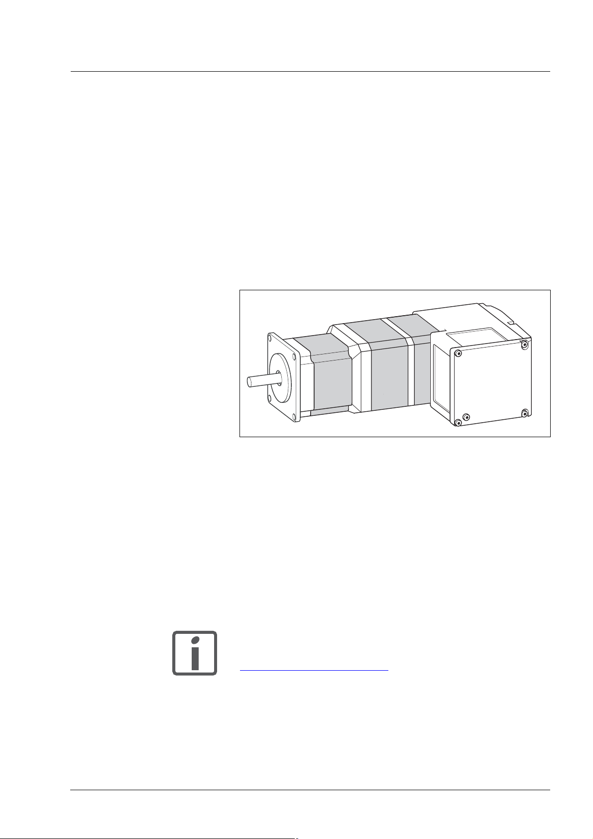
1.2 Unit overview
Figure 1.1 Device overview
The "Lexium Integrated Drive" consists of a motor and integrated electronics. The product integrates interfaces, control electronics, a holding
brake (optional) and the power stage.
Reference value supply The "Lexium Integrated Drive" moves the motor according to the com-
mands recieved by a fieldbus master, e.g. a PLC or a PC.
Safety function The integrated safety function STO (IEC 61800-5-2) meets the require-
ments of Safety Integrity Level SIL2. The safety function allows for a category 0 stop as per EN 60204-1 without external power contactors. It is
not necessary to interrupt the supply voltage. This reduces the system
costs and the response times.
The STO safety function is available as of device revision RS10 (see
nameplate).
Using the library considerably facilitates controlling the
device. The library is available for download from the
Internet.
http://www.schneider-electric.com
0198441113562, V2.00, 09.2008
Lexium Integrated Drive 11
Page 12
1 Introduction ILA1B, ILA1F, ILA1R
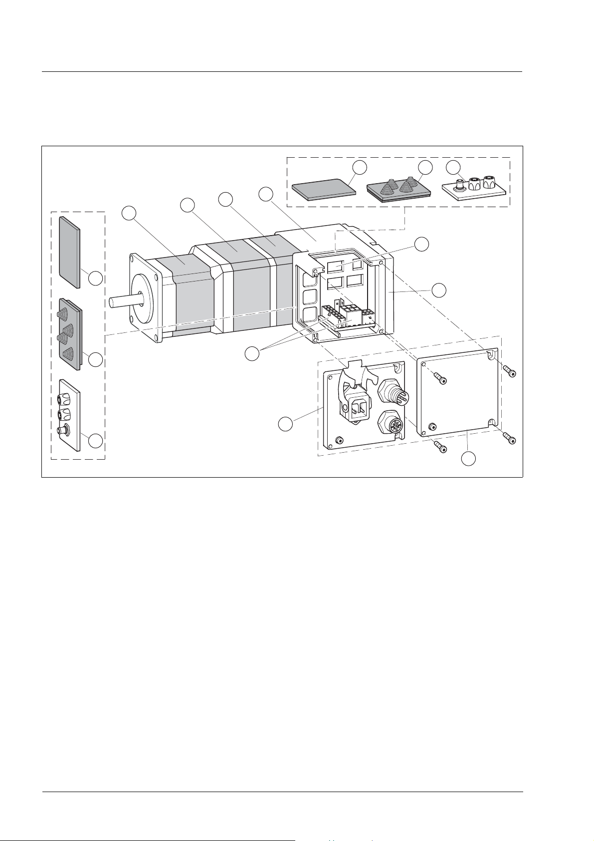
1.3 Components and interfaces
6 75
1
2
5
6
7
3
4
8
9
12
11
10
Figure 1.2 Components and interfaces
(1) Synchronous AC servo motor
(2) Holding brake (optional)
(3) Encoder
(4) Electronics housing
(5) Insert for sealing (accessory)
(6) Insert with cable entry (accessory)
(7) I/O insert with industrial connector (accessory)
(8) Switches for settings
(9) Cover of electronics housing, must not be removed
(10) Cover of connector housing, to be removed for installation
(11) Cover with industrial connector for Vdc supply voltage and IN/
OUT fieldbus connection (optional)
(12) Electrical interfaces
12 Lexium Integrated Drive
0198441113562, V2.00, 09.2008
Page 13

ILA1B, ILA1F, ILA1R 1 Introduction
1.3.1 Components
Motor The motor is a brushless AC synchronous servo motor with 3-phase
technology. The motor has a high power density due to the use of the latest magnetic materials and an optimized design.
Encoder The standard drive system operates with a singleturn encoder.
The singleturn encoder has an internal resolution of 16384 increments
per revolution.
The drive system can optionally be equipped with a multiturn encoder.
The multiturn encoder covers a range of 4096 motor revolutions.
Electronics The electronic system comprises control electronics and power stage.
They have a common power supply and are not galvanically isolated.
The drive can be parameterized and controlled via the fieldbus interface.
4 digital 24V signals are also available. Each of them can be used as an
input or output.
Holding brake The drive can optionally be equipped with an integrated holding brake.
The holding brake is controlled automatically.
0198441113562, V2.00, 09.2008
Lexium Integrated Drive 13
Page 14

1 Introduction ILA1B, ILA1F, ILA1R
1.3.2 Interfaces
Standard available interfaces:
Supply voltage VDC The supply voltage VDC supplies the control electronics and the power
stage.
The ground connections of all interfaces are galvanically
connected. For more information see chapter 5.2 "Ground
design". This chapter also provides information on
protection against reverse polarity.
Fieldbus interface Functions:
• Profibus DP connection
• CAN bus connection
• RS485 bus connection
The fieldbus interface is used for parameterizing and controlling the
drive. The fieldbus interface allows the drive to be integrated into a fieldbus network and controlled by a master such as a PLC.
The drive can be commissioned via any of the above interfaces. This requires, for example, a PC with a suitable fieldbus converter (e.g. USBCAN). The commissioning software is available for PCs; it supports the
various fieldbus versions.
The firmware can be updated via any of the interfaces.
24 V signal interface 4 digital 24V signals are available. Each of them can be used as an input
or outputs.
The 24V signals are availab le to the master controller. However, it is
also possible to parameterize special functions such as connection of
limit switches.
14 Lexium Integrated Drive
0198441113562, V2.00, 09.2008
Page 15
ILA1B, ILA1F, ILA1R 1 Introduction
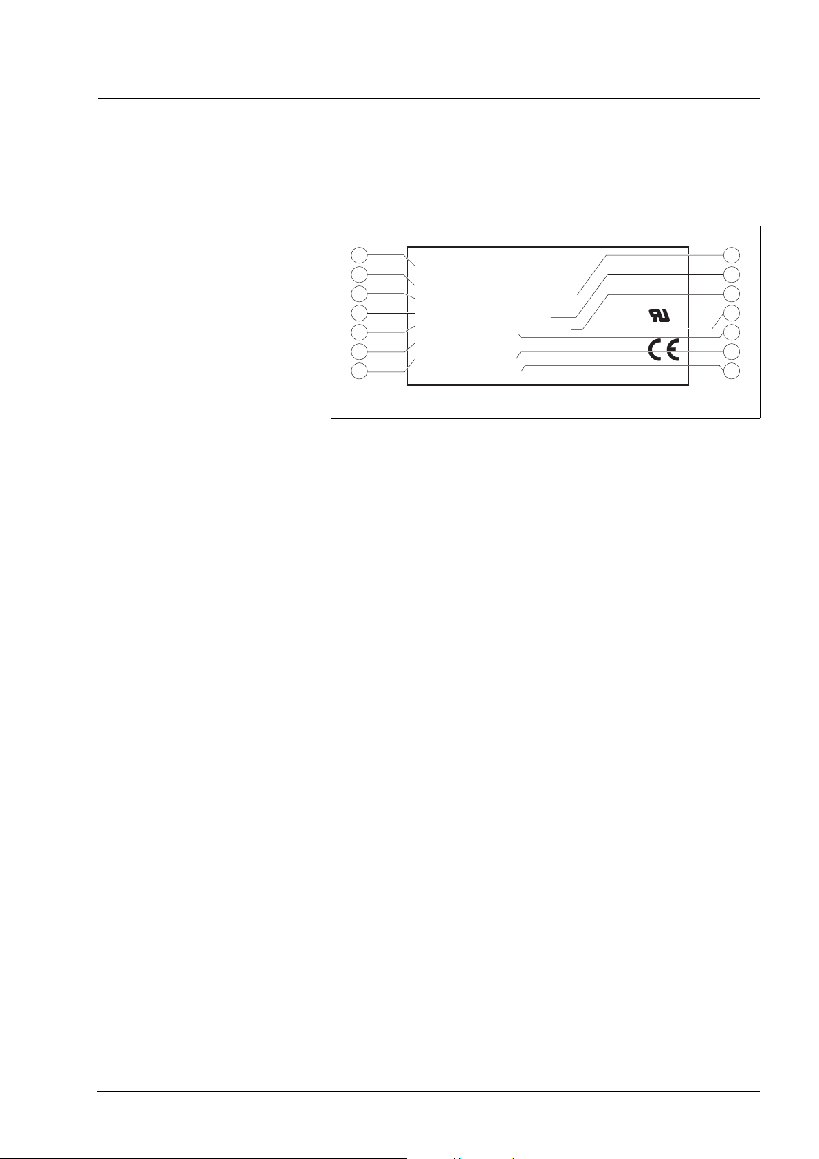
1.4 Name plate
The nameplate contains the following data:
1
2
3
4
5
6
7
Figure 1.3 Nameplate
IL ...
I ...
U
N
M
N
I
max
n
N
DOM
Insulation class
T
ambmax
PR
ID
SN
Rev
made in Germany
(1) Type code
(2) Type code (old designation)
(3) Nominal voltage
(4) Nominal torque
(5) Maximum input current
(6) Nominal speed
(7) Date of manufacture
(8) Thermal class
(9) Maximum ambient air temperature
(10) Software revision
(11) Hardware revision
(12) Firmware number
(13) Material number
(14) Serial Number
RS
8
9
10
USC
11
12
13
14
0198441113562, V2.00, 09.2008
Lexium Integrated Drive 15
Page 16

1 Introduction ILA1B, ILA1F, ILA1R
1.5 Type code
ILA 1F57 1PB1A0--
Motor
ILA = Servo motor
Supply voltage
1 = 24 ... 36 V
Communication interface
B = PROFIBUS DP
F = CANopen DS301
R = RS485
Size
57 = 57 mm
DC
Length
1 = 1 stack
2 = 2 stacks
Winding
P = Medium speed of rotation/medium torque
T = High speed of rotation/low torque
Connection version
B = Printed circuit board connector
C = Industrial connector
Position capture
1 = Servo Singleturn
2 = Servo Multiturn
Holding brake
A = Without holding brake
F = With holding brake
Gearbox
0 = Without gearbox
1)
.
2)
Reserved
1) Not available in combination with the holding brake option
2) Not available in combination with the servo multiturn option.
Customized product In the case of a customized product, position 9 is an "S".
Positions 10 ... 13 are the number of the customized product.
Example: IL••••••S1234--
16 Lexium Integrated Drive
0198441113562, V2.00, 09.2008
Page 17

ILA1B, ILA1F, ILA1R 1 Introduction
1.6 Documentation and literature references
The following manuals belong to this product:
• Product manual, describes the technical data, installation, commissioning and all operating modes and functions.
• Fieldbus manual, description required to integrate the product into
a fieldbus.
Source product manuals The current product manuals are available for download from the Inter-
net.
http://www.schneider-electric.com
Source EPLAN Macros For easier engineering, macro files and product master data are availa-
ble for download from the Internet at:
http://www.schneider-electric.com
Additional literature We recommend the following literature for more in-depth information:
• Ellis, George: Control System Design Guide. Academic Press
• Kuo, Benjamin; Golnaraghi, Farid: Automatic Control Systems. John
Wiley & Sons
0198441113562, V2.00, 09.2008
Lexium Integrated Drive 17
Page 18

1 Introduction ILA1B, ILA1F, ILA1R
1.7 Declaration of conformity
SCHNEIDER ELECTRIC MOTION DEUTSCHLAND GmbH & Co. KG
Breslauer Str. 7 D-77933 Lahr
EC DECLARATION OF CONFORMITY
EAR 2008
Y
according to EC Directive Machinery 98/37/EC
according to EC Directive EMC 2004/108/EC
according to EC Directive Low Voltage 2006/95/EC
We declare that the products listed below meet the requirements of the mentioned EC
Directives with respect to design, construction and version distributed by us. This
declaration becomes invalid with any modification on the products not authorized by us.
Designation: Motors with integrated control electronics
Type: ILA, ILE, ILS
Product number: 0x6600xxxxxxx, 0x6610xxxxxxx, 0x66206xxxxxx, 0x66307xxxxxx
0x6640xxxxxxx, 0x66606xxxxxx, 0x66707xxxxxx
Applied
harmonized
standards,
especially:
EN ISO 13849-1:2006, Performance Level "d" (category 3)
EN 61800-3:2004, second environment
EN 62061:2005, SILcl 2
EN 61508:2001, SIL 2
Applied
national standards
UL 508C
Product documentation
and technical
specifications,
especially:
Company stamp:
Date/ Signature: 10 July 2008
Name/ Department: Wolfgang Brandstätter/Development
18 Lexium Integrated Drive
0198441113562, V2.00, 09.2008
Page 19
ILA1B, ILA1F, ILA1R 1 Introduction
1.8 TÜV certificate for functional safety
0198441113562, V2.00, 09.2008
Lexium Integrated Drive 19
Page 20

1 Introduction ILA1B, ILA1F, ILA1R
20 Lexium Integrated Drive
0198441113562, V2.00, 09.2008
Page 21

ILA1B, ILA1F, ILA1R 2 Before you begin - safety information
2 Before you begin - safety information
2.1 Qualification of personnel
Only appropriately trained persons who are familiar with and understand
the contents of this manual and all other pertinent product documentation are authorized to work on and with this product. In addition, these
persons must have received safety training to recognize and avoid hazards involved. These persons must have sufficient technical training,
knowledge and experience and be able to foresee and detect potential
hazards that may be caused by using the product, by changing the settings and by the mechanical, electrical and electronic equipment of the
entire system in which the product is used.
All persons working on and with the product must be fully familiar with all
applicable standards, directives, and accident prevention regulations
when performing such work.
2.2 Intended use
This product is a motor with an integrated drive and intended for industrial use according to this manual.
The product may only be used in compliance with all applicable safety
regulations and directives, the specified requirements and the technical
data.
Prior to using the product, you must perform a risk assessment in view
of the planned application. Based on the results, the appropriate safety
measures must be implemented.
Since the product is used as a component in an entire system, you must
ensure the safety of persons by means of the design of this entire system (e.g. machine design).
Operate the product only with the specified cables and accessories. Use
only genuine accessories and spare parts.
The product must NEVER be operated in explosive atmospheres (hazardous locations, Ex areas).
Any use other than the use explicitly permitted is prohibited and can result in hazards.
Electrical equipment should be installed, operated, serviced, and maintained only by qualified personnel.
0198441113562, V2.00, 09.2008
Lexium Integrated Drive 21
Page 22

2 Before you begin - safety information ILA1B, ILA1F, ILA1R
2.3 Hazard categories
Safety instructions to the user are highlighted by safety alert symbols in
the manual. In addition, labels with symbols and/or instructions are attached to the product that alert you to potential hazards.
Depending on the seriousness of the hazard, the safety instructions are
divided into 4 hazard categories.
@ DANGER
DANGER indicates an imminently hazardous situation, which, if not
avoided, will result in death or serious injury.
@ WARNING
WARNING indicates a potentially hazardous situation, which, if not
avoided, can result in death, serious injury, or equipment damage.
@ CAUTION
CAUTION indicates a potentially hazardous situation, which, if not
avoided, can result in injury or equipment damage.
CAUTION
CAUTION used without the safety alert symbol, is used to address
practices not related to personal injury (e.g. can result in equipment
damage).
22 Lexium Integrated Drive
0198441113562, V2.00, 09.2008
Page 23

ILA1B, ILA1F, ILA1R 2 Before you begin - safety information
2.4 Basic information
@ DANGER
UNINTENDED CONSEQUENCES OF EQUIPMENT OPERATION
When the system is started, the drives are usually out of the operator's view and cannot be visually monitored.
• Only start the system if there are no persons in the hazardous
area.
Failure to follow these instructions will result in death or serious
injury.
@ WARNING
UNEXPECTED MOVEMENT
Drives may perform unexpected movements because of incorrect wiring, incorrect settings, incorrect data or other errors.
Interference (EMC) may cause unpredictable responses in the system.
• Carefully install the wiring in accordance with the EMC requirements.
• Switch off the voltage at the inputs STO_A
(PWRR_B
switching on and configuring the drive system.
• Do NOT operate the drive system with unknown settings or data.
• Perform a comprehensive commissioning test.
Failure to follow these instructions can result in death or serious
injury.
) to avoid an unexpected restart of the motor before
(PWRR_A) and STO_B
0198441113562, V2.00, 09.2008
Lexium Integrated Drive 23
Page 24

2 Before you begin - safety information ILA1B, ILA1F, ILA1R
@ WARNING
LOSS OF CONTROL
• The designer of any control scheme must consider the potential
failure modes of control paths and, for certain critical functions,
provide a means to achieve a safe state during and after a path
failure. Examples of critical control functions are EMERGENCY
STOP, overtravel stop, power outage and restart.
• Separate or redundant control paths must be provided for critical
functions.
• System control paths may include communication links. Consideration must be given to the implication of unanticipated transmission delays or failures of the link.
• Observe the accident prevention regulations and local safety
guidelines.
• Each implementation of the product must be individually and thoroughly tested for proper operation before being placed into service.
Failure to follow these instructions can result in death or serious
injury.
1) For USA: Additional information, refer to NEMA ICS 1.1 (latest edition), Safety
Guidelines for the Application, Installation, and Maintenance of Solid State Control
and to NEMA ICS 7.1 (latest edition), Safety Standards for Construction and
Guide for Selection, Installation for Construction and Operation of AdjustableSpeed Drive Systems.
1)
2.5 Functional safety
@ CAUTION
UNEXPECTED BEHAVIOR AND DESTRUCTION OF SYSTEM COMPONENTS
When you work on the wiring and when you unplug or plug in connectors, this may cause unexpected behavior and destruction of system
components.
• Switch the power supply off before working on the wiring.
Failure to follow these instructions can result in injury or equipment damage.
Using the safety functions integrated in this product requires careful
planning. For more information see chapter5.3 "Safety function STO
("Safe Torque Off")" on page 40.
24 Lexium Integrated Drive
0198441113562, V2.00, 09.2008
Page 25

ILA1B, ILA1F, ILA1R 2 Before you begin - safety information
2.6 Standards and terminology
Technical terms, terminology and the corresponding descriptions in this
manual are intended to use the terms or definitions of the pertinent
standards.
In the area of drive systems, this includes, but is not limited to, terms
such as "safety function", "safe state", "fault", "fault reset", "failure", "error", "error message", "warning", "warning message", "alarm", etc.
Among others, these standards include:
• IEC 61800 series: "Adjustable speed electrical power drive systems"
• IEC 61800-7 series: "Adjustable speed electrical power drive systems - Part 7-1: Generic interface and use of profiles for power drive
systems - Interface definition"
• IEC 61158 series: "Industrial communication networks - Fieldbus
specifications"
• IEC 61784 series: "Industrial communication networks - Profiles"
• IEC 61508 series: "Functional safety of electrical/electronic/programmable electronic safety-related systems"
Also see the glossary at the end of this manual.
0198441113562, V2.00, 09.2008
Lexium Integrated Drive 25
Page 26

2 Before you begin - safety information ILA1B, ILA1F, ILA1R
26 Lexium Integrated Drive
0198441113562, V2.00, 09.2008
Page 27

ILA1B, ILA1F, ILA1R 3 Technical Data
3 Technical Data
This chapter contains information on the ambient conditions and on the
mechanical and electrical properties of the device family and the accessories.
3.1 Certifications
Product certifications:
Certified by Assigned number Validity
TÜV Nord SAS-1728/08 2013-01-09
UL File E 153659
Certified safety function This product has the following certified safety function:
• Safety function STO "Safe Torque Off" (IEC 61800-5-2)
3.2 Ambient conditions
Ambient temperature during
operation
Ambient conditions transportation
and storage
Temperature
The maximum permissible ambient temperature during operation depends on the distance between the devices and the required power. Observe the pertinent instructions in the chapter Installation.
Operating temperature
Operating temperature with cur-
rent reduction of 2% per Kelvin
1) Limit values with flanged motor (steel plate 300x300x10 mm)
2) If the product is to be used in compliance with UL 508C, note the information pro-
vided in chapter 3.5 "Conditions for UL 508C".
1) 2)
[°C] 0 ... 50
[°C] 50 ... 65
1)
The environment during transport and storage must be dry and free from
dust. The maximum vibration and shock load must be within the specified limits.
Temperature [°C] -25 ... +70
Max. temperature of power
1)
stage
Max. temperature of motor
1) Can be read via parameter
2) Measured on the surface
2)
[°C] 105
[°C] 110
Relative humidity The following relative humidity is permissible during operation:
Relative humidity (non-condensing)
0198441113562, V2.00, 09.2008
[%] 15 ... 85
Lexium Integrated Drive 27
Page 28

3 Technical Data ILA1B, ILA1F, ILA1R
Installation altitude The installation altitude is defined as height above sea level.
Installation altitude [m] ≤1000
Vibration and shock
EMC
Vibartion, sinusoidal As per IEC/EN 60068-2-6
Shock, semi-sinusoidal As per IEC/EN 60068-2-27:
Emission IEC/EN 61800-3: Class C2
Noise immunity IEC/EN 61800-3: Second environment
0.15 mm (from 10 Hz ... 60 Hz)
20 m/s2 (from 10 Hz ... 500 Hz)
2
150 m/s
EN 61000-6-4
EN 55022: Class A
(11 ms)
28 Lexium Integrated Drive
0198441113562, V2.00, 09.2008
Page 29
ILA1B, ILA1F, ILA1R 3 Technical Data
3.3 Mechanical data
3.3.1 Degree of protection
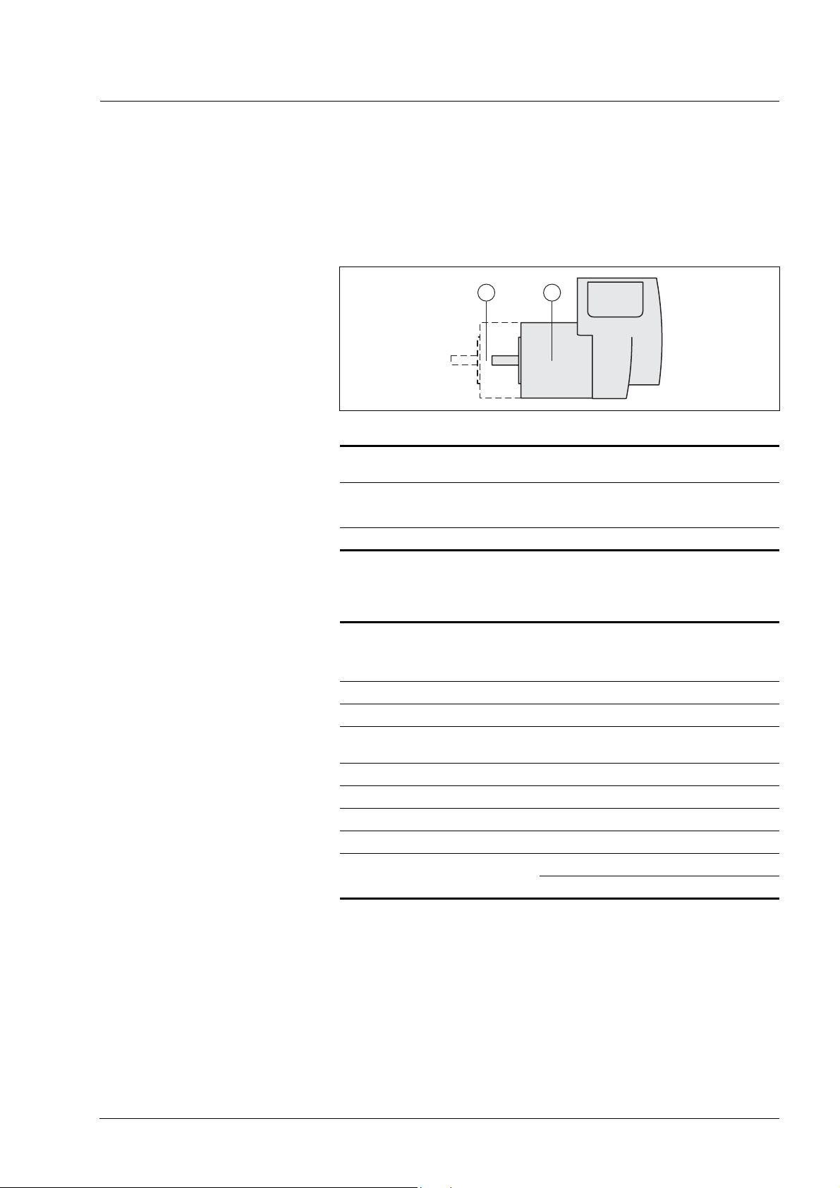
IP degree of protection The product has the following IP degree of protection as per EN 60529.
1 2
Figure 3.1 IP degree of protection
Item Degree of
protection
1 Shaft bushing
Shaft bushing with GBX gear (accessory)
2 Housing, except shaft bushing IP54
IP41
IP54
The total degree of protection is determined by the component with the
lowest degree of protection.
Overview of IP degrees of
protection
First digit Second digit
Protection against intrusion of
objects
0 No protection 0 No protection
1 External objects >50 mm 1 Vertically falling dripping water
2 External objects >12 mm 2 Dripping water falling at an angle
3 External objects >2.5 mm 3 Spraying water
4 External objects >1 mm 4 Splashing water
5 Dust-protected 5 Water jets
6 Dust-tight 6 Heavy sea
Protection against intrusion of water
(75 ° ... 90 °)
7Immersion
8Submersion
Degree of protection if STO is used You must ensure that conductive substances cannot get into the product
(pollution degree 2). If you use the safety function and conductive substances get into the product, the safety function may become inoperative.
0198441113562, V2.00, 09.2008
Lexium Integrated Drive 29
Page 30
3 Technical Data ILA1B, ILA1F, ILA1R
3.3.2 Mounting position
Mounting position The following mounting positions are defined and approved as per EN
60034-7:
• IM B5 drive shaft horizontal
• IM V1 drive shaft vertical, shaft end down
• IM V3 drive shaft vertical, shaft end up
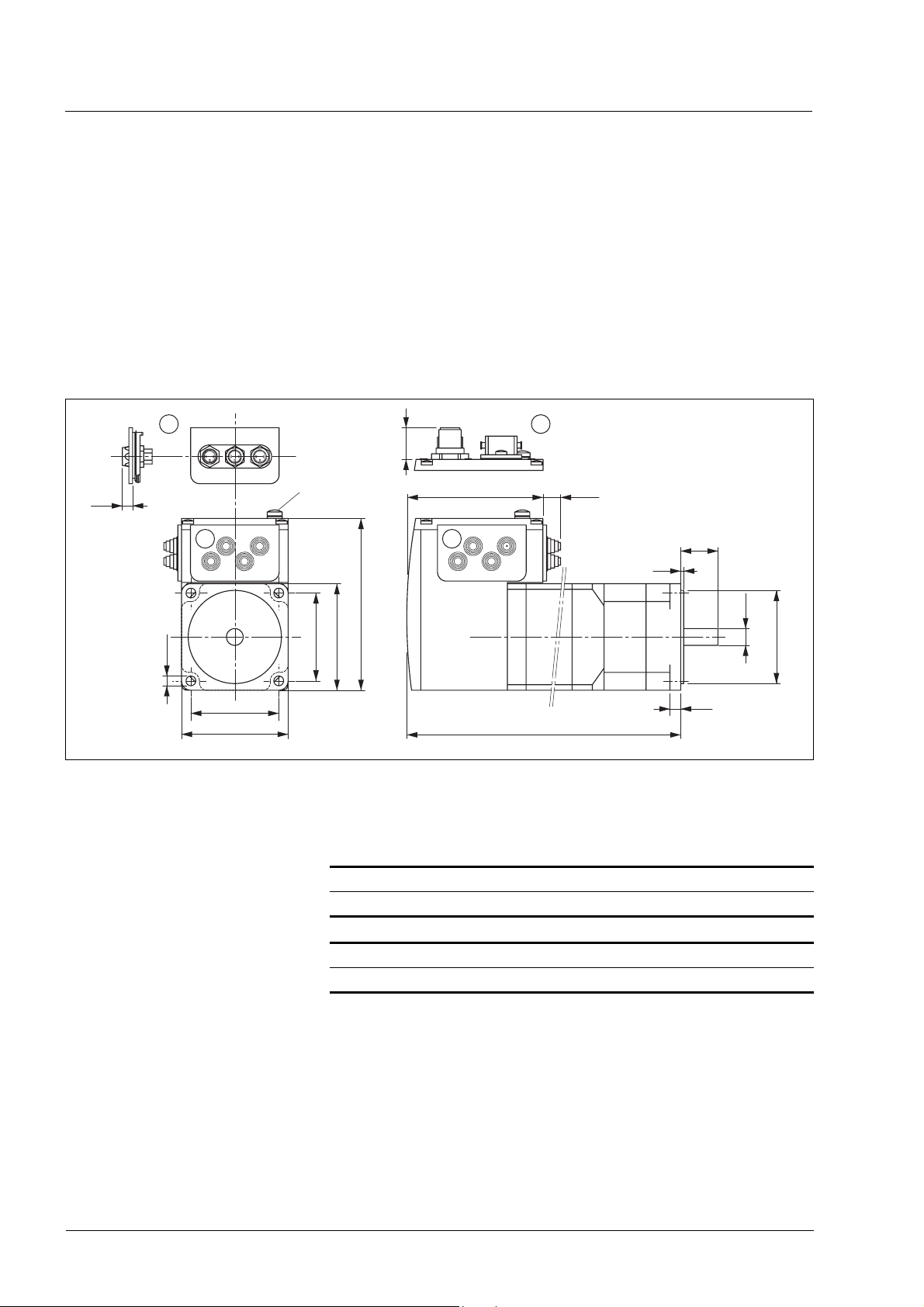
3.3.3 Dimensions
2 3
17
5.5
M4
1 1
92.2
57.2
Ø 5.2
47.14
57.2
47.14
Figure 3.2 Dimensions
(1) Insert with cable entry (accessory)
(2) Insert kit (accessory)
(3) Industrial connector (option)
Total length L
ILA••571... ••1A0 ••2A0 ••1F0
L [mm] 145.3 179.3 190.8
73
9.5
20
1.6
Ø9 j6
Ø 50 h8
5.8
L
ILA••572... ••1A0 ••2A0 ••2F0
L [mm] 163.8 197.8 209.3
30 Lexium Integrated Drive
0198441113562, V2.00, 09.2008
Page 31

ILA1B, ILA1F, ILA1R 3 Technical Data
3.4 Electrical Data
Overview of printed circuit board
connectors
Figure 3.3 Overview of printed circuit board connectors
3.4.1 Supply Voltage VDC at CN1
Nominal voltage [Vdc] 24 / 36 24 / 36
Limit values [V
Ripple at nominal voltage [Vpp] ≤3.6 ≤3.6
Max. continuous current input
Winding type P
Winding type T
Peak input current
Winding type P
Winding type T
Fuse to be connected upstream
1) The actual power requirement is often significantly lower, because the maximum
possible motor torque is usually not required for operation of a system.
2) See chapter 5.1.1 "Supply voltage"
71
82
9 3
10 4
11 5
12 6
0VDC
CN1
VDC
123
456
dc
1)
2)
[A]
[A]
[A] ≤16 ≤16
CN5
1
2
CN6
123
456
CN4CN3CN2
ILA1•571 ILA1•572
] 18 ... 40 18 ... 40
5
7.5
7
11
7
7.5
8.5
9
Inrush current current Charging current for capacitor C=1500 µF
0198441113562, V2.00, 09.2008
Lexium Integrated Drive 31
Page 32

3 Technical Data ILA1B, ILA1F, ILA1R
3.4.2 Fieldbus at CN2
CAN bus signals The CAN bus signals comply with the ISO 11898 standard and are not
galvanically isolated.
Transmission rate [kBaud] 50 / 100 / 125 / 250 / 500 / 800 /
Transmission protocol CANopen as per DS301
1000
Profibus signals The Profibus signals comply with the RS485 standard and are galvani-
cally isolated.
Transmission rate [kBaud] 9.6 / 19.2 / 45.45 / 93.75 / 187.5 /
500 / 1500 / 3000 / 6000 / 12000
Transmission protocol Profibus DP V0
3.4.3 Reference value supply to CN2
Pulse/direction, A/B/I input signals Reference signals for operating mode Electronic Gear
Symmetrical Conforming to RS422
Input frequency pulse/direction [kHz] ≤200
Input frequency A/B [kHz] ≤200
3.4.4 Fieldbus at CN3
RS485 signals The RS485 signals conform to the RS485 standard and are not galvan-
ically isolated.
3.4.5 24V signals to CN4
Signal inputs The signal inputs are galvanically connected to 0VDC and not protected
Transmission rate [kBaud] 9.6 / 19.2 / 38.4
Transmission protocol Manufacturer-specific protocol
against reverse polarity.
Logic 0 (U
Logic 1 (U
Input current (typical at 24V) [mA] 2
Debounce time IO0 ... IO3 [ms] 0.1
Debounce time IO2 and IO3
1) When the function "Fast Position Capture is used"
) [V] -3 ... +4.5
low
) [V] +15 ... +30
high
1)
[ms] 0.01
32 Lexium Integrated Drive
0198441113562, V2.00, 09.2008
Page 33

ILA1B, ILA1F, ILA1R 3 Technical Data
Signal outputs The signal outputs are galvanically connected to 0VDC and short-circuit
protected.
Nominal voltage [V] 24
Voltage range [V] 23 ... 25
Maximum current (total) [mA] 200
Maximum current per output [mA] 100
Suitable for inductive loads [mH] 1000
3.4.6 STO safety function at CN5 and CN6
The signal inputs are galvanically connected to 0VDC.
Data for maintenance plan and
safety calculations
Logic 0 (U
Logic 1 (U
Input current STO_A (PWRR_A)
(typical at 24V)
Input current STO_B
(typical at 24V)
Debounce time [ms] 1
Detection of signal difference
between STO_A (PWRR_A) and
STO_B
Response time (until shutdown of
power stage)
Permitted test pulse width of
upstream devices
) [V] -3 ... +4.5
low
) [V] +15 ... +30
high
[mA] ≤10
(PWRR_B)
(PWRR_B)
[mA] ≤3
[s] ≥1
[ms] <50
[ms] <1
Use the following data of the STO safety function for your maintenance
plan and the safety calculations:
Lifetime (IEC 61508) 20 years
SFF (IEC 61508)
Safe Failure Fraction
HFT (IEC 61508)
Hardware Fault Tolerance
Type A subsystem
Safety integrity level
IEC 61508
IEC 62061
PFH (IEC 61508)
Probability of Dangerous Hardware Failure per Hour
PL (ISO 13849-1)
Performance Level
MTTF
(EN 13849-1)
d
Mean Time to Dangerous Failure
DC (EN 13849-1)
Diagnostic Coverage
[%] 66
1
SIL2
SILCL2
[1/h] 1.84*10
d (Category 3)
4566 years
[%] 90
-9
0198441113562, V2.00, 09.2008
Lexium Integrated Drive 33
Page 34

3 Technical Data ILA1B, ILA1F, ILA1R
3.5 Conditions for UL 508C
If the product is used to comply with UL 508C, the following conditions
must be met:
Ambient temperature during
operation
Pollution degree Use in an environment with pollution degree 2.
Power supply Use only power supply units that are approved for overvoltage category
Wiring Use only 60/75 °C copper conductors.
Surrounding air temperature [°C] 0 ... +50
Surrounding air temperature with
current reduction of 2% per Kelvin
III.
[°C] 50 ... 65
34 Lexium Integrated Drive
0198441113562, V2.00, 09.2008
Page 35

ILA1B, ILA1F, ILA1R 4 Basics
4Basics
4.1 Functional safety
Automation and safety engineering are two areas that were completely
separated in the past but recently have become more and more integrated. Engineering and installation of complex automation solutions
are greatly simplified by integrated safety functions.
Usually, the safety engineering requirements depend on the application.
The level of the requirements results from the risk and the hazard potential arising from the specific application.
Working with IEC 61508
IEC 61508 standard The standard IEC 61508 "Functional safety of electrical/electronic/pro-
grammable electronic safety-related systems" covers the safety-related
function. It is not only one single component but the entire function chain
(e.g. from the sensor through the logical processing unit to the actuator)
that is considered as one single unit. This function chain must meet the
requirements of the specific safety integrity level as a whole. Systems
and components that can be used in various applications for safety tasks
with comparable risk levels can be developed on this basis.
SIL, Safety Integrity Level The standard IEC 61508 defines 4 safety integrity levels (SIL) for safety
functions. SIL1 is the lowest level and SIL4 is the highest level. A hazard
and risk analysis serves as a basis for determining the required safety
integrity level. This is used to decide whether the relevant function chain
is to be considered as a safety function and which hazard potential it
must cover.
PFH, Probability of a dangerous
hardware failure per hour
To maintain the safety function, the IEC 61508 standard requires various levels of measures for avoiding and controlling faults, depending on
the required SIL. All components of a safety function must be subjected
to a probability assessment to evaluate the effectiveness of the measures implemented for controlling faults. This assessment determines the
PFH (probability of a dangerous failure per hour) for a safety system.
This is the probability per hour that a safety system fails in a hazardous
manner and the safety function cannot be correctly executed. Depending on the SIL, the PFH must not exceed certain values for the entire
safety system. The individual PFH values of a function chain are added;
the total PFH value must not exceed the maximum value specified in the
standard.
SIL PFH at high demand or continuous demand
4 ≥10-9 ... <10
3 ≥10-8 ... <10
2 ≥10-7 ... <10
1 ≥10-6 ... <10
-8
-7
-6
-5
0198441113562, V2.00, 09.2008
Lexium Integrated Drive 35
Page 36

4 Basics ILA1B, ILA1F, ILA1R
HFT and SFF Depending on the SIL for the safety system, the IEC 61508 standard re-
quires a specific hardware fault tolerance HFT in connection with a specific proportion of safe failures SFF (safe failure fraction). The hardware
fault tolerance is the ability of a system to execute the required safety
function in spite of the presence of one or more hardware faults. The
SFF of a system is defined as the ratio of the rate of safe failures to the
total failure rate of the system. According to IEC 61508, the maximum
achievable SIL of a system is partly determined by the hardware fault tolerance HFT and the safe failure fraction SFF of the system.
SFF HFT type A subsystem HFT type B
subsystem
012 012
< 60% SIL1 SIL2 SIL3 --- SIL1 SIL2
60% ... <90% SIL2 SIL3 SIL4 SIL1 SIL2 SIL3
90% ... < 99% SIL3 SIL4 SIL4 SIL2 SIL3 SIL4
≥99% SIL3 SIL4 SIL4 SIL3 SIL4 SIL4
Fault avoidance measures Systematic errors in the specifications, in the hardware and the soft-
ware, usage faults and maintenance faults of the safety system must be
avoided to the maximum degree possible. To meet these requirements,
IEC 61508 specifies a number of measures for fault avoidance that must
be implemented depending on the required SIL. These measures for
fault avoidance must cover the entire life cycle of the safety system, i.e.
from design to decommissioning of the system.
36 Lexium Integrated Drive
0198441113562, V2.00, 09.2008
Page 37

ILA1B, ILA1F, ILA1R 5 Engineering
5 Engineering
This chapter contains information on the application of the product that
is vital in the design phase.
5.1 External power supply units
@ DANGER
ELECTRIC SHOCK CAUSED BY INCORRECT POWER SUPPLY UNIT
The VDC and +24VDC supply voltages are connected with many exposed signal connections in the drive system.
• Use a power supply unit that meets the PELV (Protective Extra
Low Voltage) requirements.
• Connect the negative output of the power supply unit to PE
(ground).
Failure to follow these instructions will result in death or serious
injury.
5.1.1 Supply voltage
General The power supply unit must be rated for the power requirements of the
drive. The input current can be found in the technical data.
The actual power requirements are often significantly lower because the
maximum possible motor torque is usually not required for normal operation of a system.
When designing the system, note that the input current of the drive is
higher during the motor acceleration phase than during constant movement.
Protection against reverse polarity In the case of reverse polarity, the supply voltage is short-circuited. The
drive is continuous short circuit-proof up to a short-circuit current of a
maximum of 15 A. If the power is supplied by a transformer power supply
unit, several hundred amperes may flow for a short period of time in the
event of reverse polarity; the drive is rated for this and will not be damaged.
Fuse: a circuit-breaker (16 A, trip characteristic B) or a blade fuse (FKS,
max. 15 A) or a fuse (5 mm x 20 mm, 10 A slow-blow).
0198441113562, V2.00, 09.2008
Lexium Integrated Drive 37
Page 38

5 Engineering ILA1B, ILA1F, ILA1R
Regeneration condition Note the following for drives with large external mass moments of inertia
or for highly dynamic applications:
Motors return regeneration energy during deceleration. The DC bus can
store a limited amount of energy in the capacitors. Connecting additional
capacitors to the DC bus increases the amount of energy that can be
stored.
If the capacity of the capacitors is exceeded, the excess energy must be
discharged via internal or external braking resistors. If the energy is not
discharged, an overvoltage monitor will shut off the power stage.
Overvoltages can be limited by adding a braking resistor with a corresponding braking resistor controller. This converts the regenerated energy to heat energy during deceleration.
Braking resistor controllers can be found in chapter 11 "Accessories and
spare parts". See the product manual for a description of the braking resistor controller.
@ CAUTION
LOSS OF CONTROL DUE TO REGENERATION CONDITION
Regeneration conditions resulting from braking or external driving
forces may increase the VDC supply voltage to an unexpected level.
Components not rated for this voltage may be destroyed or cause misoperation.
• Verify that all VDC consumers are rated for the voltage occurring
during regeneration conditions (for example limit switches).
• Use only power supply units that will not be damaged by regeneration conditions.
• Use a braking resistor controller, if necessary.
Failure to follow these instructions can result in injury or equipment damage.
24V signal power supply A constant 24V signal power supply is available for the sensor system.
It must not be connected in parallel with the 24V signal power supply of
a different drive.
38 Lexium Integrated Drive
0198441113562, V2.00, 09.2008
Page 39

ILA1B, ILA1F, ILA1R 5 Engineering
5.2 Ground design
The ground connections of all interfaces are galvanically connected, including the ground for the VDC supply voltage.
The module interfaces with galvanic isolation such as Profibus are exceptions to this.
The following points must be considered when you wire the drives in a
system:
• The voltage drop in the VDC power supply lines must be kept as low
as possible (less than 1 V). At higher ground potential differences
between different drives, the communication / control signals may
be affected.
• If the distance between the system components is greater, it is recommended to use decentralized power supply units close to the
individual drives to supply the VDC voltage. However, the ground
connections of the individual power supply units must be connected
with the largest possible conductor cross section.
• The internal 24V signal power supply must not be connected in parallel with the internal 24V signal power supply of a different drive.
• If the master controller (e.g. PLC, IPC etc.) does not have galvanically isolated outputs for the drives, you must verify that the current
of the VDC supply voltage has no path back to the power supply unit
via the master controller. Therefore, the master controller ground
may be connected to the VDC supply voltage ground at a single
point only. This is usually the case in the control cabinet. The
ground contacts of the various signal connectors in the drive are
therefore not connected; there is already a connection via the VDC
supply voltage ground.
• If the controller has a galvanically isolated interface for communication with the drives, the ground of this interface must be connected
to the signal ground of the first drive. This ground may be connected
to a single drive only to avoid ground loops. This also applies to a
galvanically isolated CAN connection.
Equipotential bonding conductors Potential differences can result in excessive currents on the cable
shields. Use equipotential bonding conductors to reduce currents on the
cable shields.
The equipotential bonding conductor must be rated for the maximum
current flowing. Practical experience has shown that the following conductor cross sections can be used:
•16mm
length of 200 m
•20mm
of more than 200 m
2
(AWG 4) for equipotential bonding conductors up to a
2
(AWG 4) for equipotential bonding conductors with a length
0198441113562, V2.00, 09.2008
Lexium Integrated Drive 39
Page 40

5 Engineering ILA1B, ILA1F, ILA1R
5.3 Safety function STO ("Safe Torque Off")
See page 35 for information on using the IEC 61508 standard..
5.3.1 Definitions
Safety function STO (IEC 61800-5-2)The safety function STO ("Safe Torque Off", "Safe Torque Off") shuts off
the motor torque safely. It is not necessary to interrupt the supply voltage. There is no monitoring for standstill.
"Power Removal" The STO safety function ("Safe Torque Off") is also known as "Power
Removal".
Category 0 stop (EN 60204-1) Stopping by immediate removal of power to the machine actuators (i.e.
an uncontrolled stop).
Category 1 stop (EN 60204-1) Controlled stop with power available to the machine actuators to achieve
the stop. Power is not interrupted until the stop is achieved.
5.3.2 Function
The STO safety function integrated into the product can be used to implement an "EMERGENCY STOP" (EN 60204-1) for category 0 stops.
With an additional, approved EMERGENCY STOP module, it is also
possible to implement category 1 stops.
Function principle The STO safety function is triggered via 2 redundant inputs. The circuits
of the two inputs must be separate so that there are always two channels.
The switching process must be simultaneous for both inputs (skew <1s).
The power stage is disabled and an error message is generated. The
motor can no longer generate torque and coasts down without braking.
A restart is possible after resetting the error message with a "Fault Reset".
The power stage is disabled and an error message is generated if only
one of the two inputs is switched off or if the skew is too great. This error
message can only be reset by switching off the product.
40 Lexium Integrated Drive
0198441113562, V2.00, 09.2008
Page 41

ILA1B, ILA1F, ILA1R 5 Engineering
5.3.3 Requirements for using the safety function
@ WARNING
LOSS OF SAFETY FUNCTION
Incorrect usage may cause a hazard due to the loss of the safety function.
• Observe the requirements for using the safety function.
Failure to follow these instructions can result in death or serious
injury.
Category 0 stop During a category 0 stop, the motor coasts down in an uncontrolled way.
If access to the machine coasting down involves a hazard (results of the
hazard and risk analysis), you must take appropriate measures.
Category 1 stop A controlled stop must be triggered with a category 1 stop. The control-
led stop is not monitored by the drive system; in the case of a power outage or an error, the stop may not be performed correctly. Final shutoff of
the motor is achieved by switching off the two inputs of the STO safety
function. The shutoff is usually controlled by a standard EMERGENCY
STOP module with a safe time delay.
Behavior of holding brake Triggering the STO safety function means that the delay time for motors
with holding brake is not effective. The motor cannot generate holding
torque to bridge the time to application of the holding brake. Especially
in the case of vertical axes it is important to verify whether additional
measures are required to avoid lowering of the load.
Vertical axes, external forces If external forces act on the motor (vertical axis) and an unwanted move-
ment, for example caused by gravity, could cause a hazard, the motor
must not be operated without additional measures for fall protection, corresponding to the required safety.
Unintended restart Note that a master controller must not trigger an unintended restart after
restoration of power (e.g. after a power outage).
Degree of protection if STO is used You must ensure that conductive substances cannot get into the product
(pollution degree 2). If you use the safety function and conductive substances get into the product, the safety function may become inoperative.
0198441113562, V2.00, 09.2008
Lexium Integrated Drive 41
Page 42

5 Engineering ILA1B, ILA1F, ILA1R
Protected cable installation If short circuits or cross circuits can be expected in connection with the
two signals of the STO safety function and if they are not detected by upstream devices, protected cable installation is required.
In the case of an unprotected cable installation, the two signals of the
STO safety function may be connected to external voltage if a cable is
damaged. If the two signals are connected to external voltage, the STO
safety function is no longer operative.
Protected cable installation possibilities:
• Use separate cables for two signals. Any additional wires in these
cables may only carry voltages according to PELV.
• Use a shielded cable. The grounded shield is designed to dissipate
the external voltage in the case of damages and to trip the fuse in
this way.
• Use a separately grounded shield. If there are other wires in the
cable, the two signals must be isolated from these wires by a
grounded, separate shield.
Data for maintenance plan and
safety calculations
Use the following data of the STO safety function for your maintenance
plan and the safety calculations:
Lifetime (IEC 61508) 20 years
SFF (IEC 61508)
Safe Failure Fraction
HFT (IEC 61508)
Hardware Fault Tolerance
Type A subsystem
Safety integrity level
IEC 61508
IEC 62061
PFH (IEC 61508)
Probability of Dangerous Hardware Failure per Hour
PL (ISO 13849-1)
Performance Level
(EN 13849-1)
MTTF
d
Mean Time to Dangerous Failure
DC (EN 13849-1)
Diagnostic Coverage
[%] 66
1
SIL2
SILCL2
[1/h] 1.84*10
d (Category 3)
4566 years
[%] 90
-9
Hazard and risk analysis As a system manufacturer you must conduct a hazard and risk analysis
of the entire system. The results must be taken into account in the application of the STO safety function.
The type of circuit resulting from the analysis may differ from the following application examples. Additional safety components may be required. The results of the hazard and risk analysis always have priority.
42 Lexium Integrated Drive
0198441113562, V2.00, 09.2008
Page 43

ILA1B, ILA1F, ILA1R 5 Engineering
5.3.4 Application examples STO
Example of category 0 stop Application without EMERGENCY STOP module, category 0 stop.
24V
24V
EMERGENCY
STOP
Figure 5.1 Example of category 0 stop
Please note:
• When the EMERGENCY STOP switch is tripped, this initiates a
category 0 stop
Example of category 1 stop Application with EMERGENCY STOP module, category 1 stop.
ENABLE
FAULT RESET
SPS/
CNC
Lexium
integrated
drive
STO_A (PWRR_A)
STO_B (PWRR_B)
24V 24V
24V24V 24V
Preventa
XPS-AV
Y+
Y64
Y74
Y84
Delayed
Undelayed
38
48
04
14
24
S11
S12
S13
S14
A2A1
EMERGENCY
STOP
37
47
57 58
03
13
23
S31
S21
S22
S32
Figure 5.2 Example of category 1 stop
Please note:
• The master controller must immediately trigger a controlled stop,
e.g. via the "Quick Stop" function.
• The inputs STO_A
switched off with a time delay. The delay is set at the EMERGENCY
STOP safety module. If the motor has not yet stopped when the
delay time has elapsed, it coasts down in an uncontrolled way
(uncontrolled stop).
ENABLE
FAULT RESET
SPS/CNC
Lexium
integrated
drive
STO_A (PWRR_A)
STO_B (PWRR_B)
(PWRR_A) and STO_B (PWRR_B) must be
• The specified minimum current and the permissible maximum current of the relay must be observed if the relay outputs of the EMERGENCY STOP module are used.
0198441113562, V2.00, 09.2008
Lexium Integrated Drive 43
Page 44

5 Engineering ILA1B, ILA1F, ILA1R
5.4 Monitoring functions
The monitoring functions in the product can help to guard the system
and reduce the risks involved in a system misoperation. These monitoring functions may not be used to protect persons.
The following monitoring functions are available:
Monitoring Task
Data link Error response if the link becomes inoperative
Limit switch signals Monitors for permissible range of travel
2
I
t limitation Power limitation in event of overloading
Tracking error Monitors for difference between actual motor position and reference position
STOP switch signal Stops motor with "Quick Stop"
Overvoltage and undervoltage Monitors for overvoltage and undervoltage of the supply voltage
Motor overload Monitors for excessively high current in the motor phases
Overtemperature Monitors the device for overtemperature
44 Lexium Integrated Drive
0198441113562, V2.00, 09.2008
Page 45

ILA1B, ILA1F, ILA1R 6 Installation
6 Installation
@ WARNING
LOSS OF CONTROL
• The designer of any control scheme must consider the potential
failure modes of control paths and, for certain critical functions,
provide a means to achieve a safe state during and after a path
failure. Examples of critical control functions are EMERGENCY
STOP, overtravel stop, power outage and restart.
• Separate or redundant control paths must be provided for critical
functions.
• System control paths may include communication links. Consideration must be given to the implication of unanticipated transmission delays or failures of the link.
• Observe the accident prevention regulations and local safety
guidelines.
• Each implementation of the product must be individually and thoroughly tested for proper operation before being placed into service.
Failure to follow these instructions can result in death or serious
injury.
1) For USA: Additional information, refer to NEMA ICS 1.1 (latest edition), Safety
Guidelines for the Application, Installation, and Maintenance of Solid State Control
and to NEMA ICS 7.1 (latest edition), Safety Standards for Construction and
Guide for Selection, Installation for Construction and Operation of AdjustableSpeed Drive Systems.
1)
@ CAUTION
RISK OF INJURY WHEN REMOVING CIRCUIT BOARD PLUGS
• When removing them note that the connectors must be unlocked.
– Supply voltage VDC:
Unlock by pulling at the plug housing
– Miscellaneous:
Unlock by pressing the locking lever
• Always hold the plug to remove it (not the cable).
Failure to follow these instructions can result in injury or equipment damage.
The chapter Engineering contains basic information that
you should know before starting the installation.
0198441113562, V2.00, 09.2008
Lexium Integrated Drive 45
Page 46

6 Installation ILA1B, ILA1F, ILA1R
6.1 Electromagnetic compatibility, EMC
@ WARNING
SIGNAL AND DEVICE INTERFERENCE
Signal interference can cause unexpected responses of device.
• Install the wiring in accordance with the EMC requirements.
• Verify compliance with the EMC requirements.
Failure to follow these instructions can result in death, serious
injury or equipment damage.
This drive system meets the EMC requirements according to the standard IEC 61800-3, if the described measures are implemented during installation. If it is operated outside this scope, note the following:
@ WARNING
HIGH-FREQUENCY INTERFERENCE
In a domestic environment this product may cause high-frequency interference that may require action to suppress interference.
EMC measures Effect
Keep cables as short as possible. Do not
install unnecessary cable loops, use short
cables from the star point in the control cabinet to the external ground connection.
Ground the product via the motor flange or
with a ground strap to the ground connection
at the cover of the connector housing.
Ground shields of digital signal wires at both
ends by connecting them to a large surface or
via conductive connector housings.
Connect large surface areas of cable shields,
use cable clamps and ground straps
Reduces capacitive and inductive interference.
Reduces emissions, increases
immunity.
Reduces interference affecting
the signal wires, reduces emissions
Reduces emissions.
The following cables must be shielded:
• Fieldbus cable
• STO safety function,
see the requirements in chapter 5.3.3 "Requirements for using the
safety function".
The following cables do not need to be shielded:
• Supply voltage VDC
• 24 V signal interface
46 Lexium Integrated Drive
0198441113562, V2.00, 09.2008
Page 47

ILA1B, ILA1F, ILA1R 6 Installation
Equipotential bonding conductors Potential differences can result in excessive currents on the cable
shields. Use equipotential bonding conductors to reduce currents on the
cable shields.
The equipotential bonding conductor must be rated for the maximum
current flowing. Practical experience has shown that the following conductor cross sections can be used:
•16mm
length of 200 m
•20mm
of more than 200 m
2
(AWG 4) for equipotential bonding conductors up to a
2
(AWG 4) for equipotential bonding conductors with a length
6.2 Mechanical installation
@ CAUTION
HOT SURFACES
Depending on the operation, the surface may heat up to more than
100°C (212°F).
• Do not allow contact with the hot surfaces.
• Do not allow flammable or heat-sensitive parts in the immediate
vicinity.
• Consider the measures for heat dissipation described.
• Check the temperature during test runs.
Failure to follow these instructions can result in injury or equipment damage.
@ CAUTION
MOTOR DAMAGE AND LOSS OF CONTROL
Shock or strong pressure applied to the motor shaft may destroy the
motor.
• Protect the motor shaft during handling and transportation.
• Avoid shocks to the motor shaft during mounting.
• Do not press parts onto the shaft. Mount parts to the shaft by
glueing, clamping, shrink-fitting or screwing.
Failure to follow these instructions can result in injury or equipment damage.
0198441113562, V2.00, 09.2008
Lexium Integrated Drive 47
Page 48

6 Installation ILA1B, ILA1F, ILA1R
@ WARNING
MOTOR WITHOUT BRAKING EFFECT
If power outage and faults cause the power stage to be switched off,
the motor is no longer stopped by the brake and may increase its
speed even more until it reaches a mechanical stop.
• Verify the mechanical situation.
• If necessary, use a cushioned mechanical stop or a suitable
brake.
Failure to follow these instructions can result in death, serious
injury or equipment damage.
@ WARNING
LOSS OF BRAKING FORCE DUE TO WEAR OR HIGH TEMPERATURE
Applying the holding brake while the motor is running will cause excessive wear and loss of the braking force. Heat decreases the braking force.
• Do not use the brake as a service brake.
• Note that "EMERGENCY STOPS" may also cause wear
• At operating temperatures of more than 80°C (176°F), do not
exceed a maximum of 50% of the specified holding torque when
using the brake.
Failure to follow these instructions can result in death, serious
injury or equipment damage.
To install a drive in locations difficult to access, it may be
useful to carry out the electrical installation first and then
install the fully wired drive.
Heat dissipation The motor may become very hot, e.g. in the case of incorrect arrange-
ment of multiple motor. The surface temperature of the motor must not
exceed 110 °C during continuous operation.
• Verify that the maximum temperature is not exceeded.
• Verify that there is sufficient heat dissipation, e.g. by means of good
ventilation or heat dissipation via the motor flange.
Mounting The motor is designed to be mounted using four M5 screws. The motor
flange must be mounted on a flat surface to avoid mechanical tension
from being transmitted to the housing.
Painted surfaces have an insulating effect. During mounting verify that
the motor flange is mounted in such a way as to allow for good conductivity (electrical and thermal).
Mounting distances No minimum clearances are required for installation. However, note that
the motor can become very hot.
Observe the bending radii of the cables used.
Ambient conditions Observe the permissible ambient conditions.
48 Lexium Integrated Drive
0198441113562, V2.00, 09.2008
Page 49

ILA1B, ILA1F, ILA1R 6 Installation
6.3 Electrical installation
@ WARNING
UNEXPECTED BEHAVIOR CAUSED BY FOREIGN OBJECTS
Foreign objects, deposits or humidity can cause unexpected behavior.
• Keep foreign objects from getting into the product.
• Do not remove the cover of the electronics housing. Only remove
the connector housing cover.
• Verify correct seat of seals and cable entries.
Failure to follow these instructions can result in death, serious
injury or equipment damage.
@ WARNING
LOSS OF SAFETY FUNCTION CAUSED BY FOREIGN OBJECTS
Conductive foreign objects, dust or liquids may cause the STO safety
function to become inoperative.
• You may not use the STO safety function unless you have protected the system against contamination by conductive substances.
Failure to follow these instructions can result in death or serious
injury.
@ CAUTION
DAMAGE TO SYSTEM COMPONENTS AND LOSS OF CONTROL
Interruptions of the negative connection of the controller supply voltage can cause excessively high voltages at the signal connections.
• Do not interrupt the negative connection between the power supply unit and load with a fuse or switch.
• Verify correct connection before switching on.
• Do not connect the controller supply voltage or change its wiring
while the is supply voltage present.
Failure to follow these instructions can result in injury or equipment damage.
The chapter Engineering contains basic information that
you should know before starting the installation.
The drive is equipped with parameter switches in the
connector housing. Set the parameter switches before
connecting the cables, because after connection they are
difficult to access.
0198441113562, V2.00, 09.2008
Lexium Integrated Drive 49
Page 50

6 Installation ILA1B, ILA1F, ILA1R
6.3.1 Wiring examples
The following figure shows a typical wiring example. The limit switches
and the reference switch are supplied via the internal 24V signal power
supply.
Lexium
integrated
drive
~
VDC
+
-
VDC
0VDC
CN4.6
+
LIMN
UBC60
STO_A (PWRR_A)
STO_B (PWRR_B)
CN4.1
CN4.4
CN5.1
CN5.2
CN4.3
CN4.5
CN4.2
+
LIMP
+
-
REF
Figure 6.1 Wiring example
The UBC60 braking resistor controller is available as an accessory, see
chapter 11 "Accessories and spare parts".
50 Lexium Integrated Drive
0198441113562, V2.00, 09.2008
Page 51

ILA1B, ILA1F, ILA1R 6 Installation
6.3.2 Overview of all connections
Overview of printed circuit board
connectors
The following figure shows the pin assignment of the interfaces with the
connector housing cover open.
CN5
1
2
71
82
9 3
10 4
11 5
12 6
0VDC
CN1
VDC
123
456
CN6
123
456
CN4CN3CN2
Figure 6.2 Overview of all connections
Connection Assignment
CN1 Supply voltage VDC
CN2 Interface for PROFIBUS DP and operating mode Electronic
CN3 Interface for CAN or RS485
CN4 24 V signal interface
CN5 Interface for STO safety function
CN6 Jumper for disabling STO safety function
Gear (reference signals)
The drive can be connected via cable entries or industrial connectors.
For connection via cable entries see page 52.
For connection via industrial connectors see page 55.
0198441113562, V2.00, 09.2008
Lexium Integrated Drive 51
Page 52

6 Installation ILA1B, ILA1F, ILA1R
6.3.3 Connection via cable entry
The cable specifications and pin assignments can be found in the chapters that describe the connections.
Preparing and fastening cables
1
A
70mm
10mm
2
D
Figure 6.3 Fastening the cable in the cable entry
B
C
(1) Unshielded cable
(2) Shielded cable
왘 Trim the cable bushings to fit the cable.
NOTE: The specified degree of protection IP54 can only be
achieved with properly trimmed cable bushings.
왘 (A) Strip the jacket of all cables; length 70 mm.
왘 (B) Shorten the shield to a rest of 10 mm.
왘 (C) Slide the shield braiding back over the cable jacket.
왘 (D) Loosen the strain relief.
왘 Push the cables though the strain relief.
왘 Glue EMC shielding foil around the shield.
왘 Pull the cable back to the strain relief.
왘 Fasten the strain relief.
Mounting connectors The table below lists the parts and data required for assembly. Connec-
tor housings and crimp contacts are included in the accessories kit. See
also chapter 11 "Accessories and spare parts".
Only use the special tool listed in the Accessories chapter
to release single crimp contacts from the connector
housing.
52 Lexium Integrated Drive
0198441113562, V2.00, 09.2008
Page 53

ILA1B, ILA1F, ILA1R 6 Installation
Connection Conductor cross section
of the crimp contact
[mm²]
CN1 0.75 ... 1.5 (AWG 18 ... 16)
2.5 ... 4.0 (AWG 12)
CN2 0.14 ... 0.6 (AWG 24 ... 20) 2.5 ... 3.0 43030-0007 69008-0982 Molex Micro-Fit 3.0
CN3 0.25 ... 1.0 (AWG 24 ... 18) 3.0 ... 3.5 39-00-0060 69008-0724 Molex Mini-Fit Jr.
CN4 0.14 ... 0.6 (AWG 24 ... 20) 2.5 ... 3.0 43030-0007 69008-0982 Molex Micro-Fit 3.0
CN5 0.14 ... 0.6 (AWG 24 ... 20) 2.5 ... 3.0 43030-0007 69008-0982 Molex Micro-Fit 3.0
Stripping
length [mm]
5 ... 65 ... 6 160773-6
Manufacturer's
crimp contact
no.
341001-6
Crimping
tool
654174-1 Tyco Electronics Positive Lock
Connector
manufacturer
Connector
type
1-926 522-1
43025-1200
39-01-2065
43025-0600
43645-0200
Prepare the cable for connection as follows:
왘 Strip the ends of the cable.
왘 Attach cable lugs and crimp contacts. Verify that you have the cor-
rect crimp contacts and the matching crimping tool.
왘 Slide the cable lugs and crimp contacts straight into the connector
until they snap in place.
햲
햳
햸
햴
햵
햸
햶
햷
Figure 6.4 Connectors, cable lugs and crimp contacts
(1) Supply voltage VDC
(2) Fieldbus IN for PROFIBUS DP
(3) Fieldbus OUT for PROFIBUS DP
(4) Fieldbus IN for CAN or RS485
(5) Fieldbus OUT for CAN or RS485
(6) 24 V signal interface
(7) Shield wire with EMC shield foil
0198441113562, V2.00, 09.2008
Lexium Integrated Drive 53
Page 54

6 Installation ILA1B, ILA1F, ILA1R
Mounting the cable entry
Figure 6.5 Inserting the cable entries
왘 Unscrew the connector housing cover.
NOTE: Shipping locks made of cardboard must not be used for
operating the drive. Replace all shipping locks by cable entries or
signal inserts.
왘 First adjust the parameter switches as these are difficult to access
once the cables are connected.
For a description of the parameter switches, see the chapters
describing the connections.
왘 Connect the plug of the assembled cable to the matching socket.
The plugs cannot be turned out of position and must click into place
when being plugged in.
Only pull the connector housing (not the cable).
왘 Plug the cable entry in one of the two cutouts provided. The side to
be used for the cable entry depends on the space available in your
system.
NOTE: The pointed corners of the cable entry must point in the
direction of the connector housing cover. Degree of protection IP54
is not reached if the cable entry is mounted the other way round.
왘 Close the cutout that is not used with a sealing insert for cutouts.
왘 Finally, screw the connector housing cover back into place.
If screws are lost use M3x12 only.
54 Lexium Integrated Drive
0198441113562, V2.00, 09.2008
Page 55

ILA1B, ILA1F, ILA1R 6 Installation
6.3.4 Connection with industrial connectors
Interface Connector used
Supply voltage VDC Hirschmann STASEI 200
Fieldbus PROFIBUS DP
in/out
Fieldbus CAN in/out Circular connector M12 , 5 poles, A-coded
24V signal inputs and out-
puts
Safety function STO "Safe
Torque Off" (IEC/EN 618005-2)
Because the requirements are different depending on the system configuration, pre-assembled cables specially designed for Ethernet fieldbus connections can be procured from various suppliers.
Information on pre-assembled cables, connector kits and recommended
suppliers can be found in chapter 11 "Accessories and spare parts".
Circular connector M12, 5 poles, B-coded
Circular connector M8, 3 poles
Circular connector M8, 4 poles
6.3.5 Connection of VDC supply voltage
ELECTRIC SHOCK CAUSED BY INCORRECT POWER SUPPLY UNIT
The VDC and +24VDC supply voltages are connected with many exposed signal connections in the drive system.
• Use a power supply unit that meets the PELV (Protective Extra
Low Voltage) requirements.
• Connect the negative output of the power supply unit to PE
(ground).
Failure to follow these instructions will result in death or serious
injury.
LOSS OF CONTROL DUE TO REGENERATION CONDITION
Regeneration conditions resulting from braking or external driving
forces may increase the VDC supply voltage to an unexpected level.
Components not rated for this voltage may be destroyed or cause misoperation.
@ DANGER
@ CAUTION
• Verify that all VDC consumers are rated for the voltage occurring
during regeneration conditions (for example limit switches).
• Use only power supply units that will not be damaged by regeneration conditions.
• Use a braking resistor controller, if necessary.
Failure to follow these instructions can result in injury or equipment damage.
0198441113562, V2.00, 09.2008
Lexium Integrated Drive 55
Page 56

6 Installation ILA1B, ILA1F, ILA1R
CAUTION
DAMAGE TO CONTACTS
The connection for the controller supply voltage at the product does
not have an inrush current limitation. If the voltage is switched on by
means of switching of contacts, damage to the contacts or contact
welding may result.
• Use a power supply unit that limits the peak value of the output
current to a value permissible for the contact.
• Switch the power input of the power supply unit instead of the
output voltage.
Failure to follow these instructions can result in equipment damage.
@ CAUTION
DAMAGE TO SYSTEM COMPONENTS AND LOSS OF CONTROL
Interruptions of the negative connection of the controller supply voltage can cause excessively high voltages at the signal connections.
• Do not interrupt the negative connection between the power supply unit and load with a fuse or switch.
• Verify correct connection before switching on.
• Do not connect the controller supply voltage or change its wiring
while the is supply voltage present.
Failure to follow these instructions can result in injury or equipment damage.
Cable specifications and terminal Two different crimp contacts are available for different conductor cross
sections, see chapter 6.3.3 "Connection via cable entry".
Minimum conductor cross section [mm2] 0.75 (AWG 18)
Maximum connection cross section [mm
Stripping length [mm] 5 ... 65 ... 6
Crimp contact 1607736-6
Minimum connection cross section
Maximum connection cross section
Crimp contact 341001-6
Minimum connection cross section
Maximum connection cross section
2
] 4.0 (AWG 12)
2
[mm
]
0.75 (AWG 18)
1.5 (AWG 16)
2
[mm
]
2.5 (AWG 12)
4.0 (AWG 12)
Unshielded cables may be used for the VDC supply voltage. Twisted pair
is not required.
왘 Use pre-assembled cables to reduce the risk of wiring errors.
왘 Verify that wiring, cables and connected interfaces meet the PELV
requirements.
56 Lexium Integrated Drive
0198441113562, V2.00, 09.2008
Page 57

ILA1B, ILA1F, ILA1R 6 Installation
Connecting the cables
Pin assignment printed circuit board
connector
왘 Note the specified technical data.
왘 Note the information provided in chapters 5.1 "External power sup-
ply units" and 5.2 "Ground design".
왘 Install fuses for the power supply cable accordance with the
selected conductor cross section / wire gauge (note the inrush currents).
CN5
1
2
71
82
9 3
10 4
11 5
12 6
0VDC
CN1
VDC
123
456
CN6
123
456
CN4CN3CN2
Figure 6.6 Pin assignment supply voltage
Pin assignment industrial connector
Signal Meaning Number
1)
VDC Supply voltage 1
OVDC Reference potential to VDC 2
1) Information relates to pre-assembled cables
You can crimp together two wires to supply multiple drives via one DC
bus. Two different crimp contacts are available for different conductor
cross sections, see chapter 6.3.3 "Connection via cable entry".
IN
VDC
21
OUT
Figure 6.7 Pin assignment supply voltage
Pin Signal Meaning Number
1 VDC Supply voltage 1
2 OVDC Reference potential to VDC 2
1) Information relates to pre-assembled cables
1 VDC
2 0VDC
1)
0198441113562, V2.00, 09.2008
Lexium Integrated Drive 57
Page 58

6 Installation ILA1B, ILA1F, ILA1R
6.3.6 PROFIBUS DP connection
Function The PROFIBUS DP interface allows you to network the product as a
slave in a Profibus network.
The drive system receives data and commands from a master bus device. Status information such as operating state and processing state is
sent to the master as acknowledgement.
The fieldbus manual for the product provides detailed description on
fieldbus networking.
Cable specifications and terminal • Shielded cable
• Twisted-pair cables
• Grounding of the shield at both ends
Maximum cable length [m] See next table
Minimum conductor cross section [mm
Maximum connection cross section [mm2] 0.6 (AWG 20)
Stripping length [mm] 2.5 ... 3.0
2
] 0.34 (AWG 24)
The maximum cable length depends on the baud rate and the signal
propagation delay. The higher the baud rate, the shorter the bus cable
needs to be.
Baud rate [kBaud] Max. cable length [m]
9.6 1200
19.2 1200
45.45 1200
93.75 1200
187.5 1000
500 400
1500 200
3000 100
6000 100
12000 100
왘 Use equipotential bonding conductors, see page 46.
왘 Use pre-assembled cables to reduce the risk of wiring errors.
왘 Verify that wiring, cables and connected interfaces meet the PELV
requirements.
Terminating resistor Both ends of the entire bus system must be terminated with a terminat-
ing resistor.
The terminating resistor is already integrated and can be activated at the
end of the network with a switch.
The diagram below shows the integrated terminating resistor.
58 Lexium Integrated Drive
0198441113562, V2.00, 09.2008
Page 59

ILA1B, ILA1F, ILA1R 6 Installation
VP
RxD/TxD-P
RxD/TxD-N
DGND
Figure 6.8 Terminating resistor
Setting address and baud rate Every device on the network is identified by a unique, adjustable node
address. Slaves on a Profibus network may have addresses in the range
from 3 to 126. Addresses 0 to 2 are reserved for master devices.
The baud rate is detected automatically.
Factory settings:
•Address: 126
• Terminating resistor: OFF
ON
OFF
1 2345678
S1
LED S2
ON
OFF
1
Bit6...................Bit0
Figure 6.9 Parameter switch
Switch setting S1: S1.2 S1.3 S1.4 S1.5 S1.6 S1.7 S1.8
Address bit: 6543210
Fieldbus address 126 (default)1111110
Fieldbus address 25 (example)0011001
Switch setting S2: S2.1
Terminating resistor on ON
Terminating resistor off OFF
LED Communication indicator
LED on Communication OK
LED off No communication
Reserved parameter switches are provided for future extensions and
must be set to OFF.
0198441113562, V2.00, 09.2008
Lexium Integrated Drive 59
Page 60

6 Installation ILA1B, ILA1F, ILA1R
NOTE: Each device must have its own unique node address, which may
only be assigned once in the network.
Pin assignment printed circuit board
connector
CN5
1
2
71
82
9 3
10 4
11 5
12 6
0VDC
CN1
VDC
123
456
CN6
123
456
CN4CN3CN2
Figure 6.10 Pin assignment of Profibus fieldbus interface
Pin Signal Meaning (Color1))
12 RxD/TxD-N Profibus interface (green) IN 8
11 RxD/TxD-P Profibus interface (red) IN 3
6 RxD/TxD-N Profibus interface (green) OUT 8
5 RxD/TxD-P Profibus interface (red) OUT 3
1) Information refers to pre-assembled cables
SUB-D
1)
Pin assignment industrial connector
IN
VDC
OUT
1
5
2
2
4
1 -
3
3
5
4
1
2 RxD/TxD-N
3 4 RxD/TxD-P
5 -
SHLD SHLD
Figure 6.11 Pin assignment of Profibus fieldbus interface
Pin Signal Meaning
2 RxD/TxD-N Profibus interface
4 RxD/TxD-P Profibus interface
5 Internally connected to housing
The shield of the cable (SHLD) must be connected to the connector
housing.
60 Lexium Integrated Drive
0198441113562, V2.00, 09.2008
Page 61

ILA1B, ILA1F, ILA1R 6 Installation
6.3.7 CAN connection
Function The CAN interface allows you to network the product as a slave in a
CANopen network as per DS301.
The drive system receives data and commands from a master bus device. Status information such as operating state and processing state is
sent to the master as acknowledgement.
The fieldbus manual for the product provides detailed description on
fieldbus networking.
Cable specifications and terminal • Shielded cable
• Twisted-pair cables
• Grounding of the shield at both ends
Maximum cable length [m] See next table
Minimum conductor cross section [mm
Maximum connection cross section [mm2] 1.0 (AWG 18)
Stripping length [mm] 3.0 ... 3.5
2
] 0.25 (AWG 22)
The maximum cable length depends on the number of network devices,
the baud rate and the signal propagation delay. The higher the baud
rate, the shorter the bus cable needs to be.
Baud rate [kBaud] Max. cable length [m]
1000 25
800 80
500 100
250 250
100 600
50 1000
왘 Use equipotential bonding conductors, see page 46.
왘 Use pre-assembled cables to reduce the risk of wiring errors.
왘 Verify that wiring, cables and connected interfaces meet the PELV
requirements.
Terminating resistor Both ends of the entire bus system must be terminated with a terminat-
ing resistor.
The terminating resistor is already integrated and can be activated at the
end of the network with a switch.
Fieldbus Terminating resistor
CAN-Bus 120 Ω between CAN_H and CAN_L
0198441113562, V2.00, 09.2008
Lexium Integrated Drive 61
Page 62

6 Installation ILA1B, ILA1F, ILA1R
Setting address and baud rate Every device on the network is identified by a unique, adjustable node
address.
Factory settings:
• Address: 127
• Baud rate: 125 kBaud
ON
OFF
res. (OFF)
ON
OFF
S1
123 4
Bit
654
High address
S3
1
234
Hex kBaud
0150
2 100
3 125
4 250
5 500
6 800
7 1000
8..F
-
ON
OFF
res. (OFF)
interface mode
(ON = "A/B", OFF = "PULSE/DIR")
terminating resistor
(ON = on)
res. (OFF)
S4
0
1
F
2
E
D
C
B
6
7
A
8
9
baud rate
S2
123 4
2103Bit
Low address
3
4
5
Figure 6.12 Parameter switch
Switch settings S1 and S2: S1.2 S1.3 S1.4 S2.1 S2.2 S2.3 S2.4
Address bit: 6543210
Fieldbus address 127 (default)1111111
Fieldbus address 25 (example)0011001
Switch setting S4 Baud rate (Kbaud)
150
2 100
3 125
4 250
5 500
6 800
7 1000
Reserved parameter switches are provided for future extensions and
must be set to OFF.
62 Lexium Integrated Drive
0198441113562, V2.00, 09.2008
Page 63

ILA1B, ILA1F, ILA1R 6 Installation
NOTE: Each device must have its own unique node address, which may
only be assigned once in the network.
Pin assignment printed circuit board
connector
Pin assignment industrial connector
CN5
1
2
71
82
9 3
10 4
11 5
12 6
0VDC
CN1
VDC
123
456
CN6
123
456
CN4CN3CN2
Figure 6.13 Pin assignment of CAN fieldbus interface
Pin Signal Meaning SUB-D
3 CAN_H CAN interface 7
6 CAN_L CAN interface 2
4 CAN_0V Internally connected to CN1.0VDC 3
1) Information relates to pre-assembled cables
1)
VDC
IN
OUT
1
5
2
2
4
1 SHLD
3
3
5
4
1
2 3 CAN_0V
4 CAN_H
5 CAN_L
1
3
4
5
Figure 6.14 Pin assignment of CAN fieldbus interface
Pin Signal Meaning
1 SHLD Shield connection
2 - internally bridged from IN to OUT
3 CAN_0V Internally connected to CN1.0VDC
4 CAN_H CAN interface
5 CAN_L CAN interface
0198441113562, V2.00, 09.2008
Lexium Integrated Drive 63
Page 64

6 Installation ILA1B, ILA1F, ILA1R
6.3.8 RS485 connection
Function The drive system is commissioned via the RS485 interface and the com-
missioning software.
In addition, the RS485 interface allows you to network the product as a
slave in an RS485 network.
The fieldbus manual for the product provides detailed description on
fieldbus networking.
Cable specifications and terminal • Shielded cable
• Twisted-pair cables
• Grounding of the shield at both ends
Maximum cable length [m] 400
Minimum conductor cross section [mm
Maximum connection cross section [mm2] 1.0 (AWG 18)
Stripping length [mm] 3.0 ... 3.5
2
] 0.25 (AWG 22)
왘 Use equipotential bonding conductors, see page 46.
왘 Use pre-assembled cables to reduce the risk of wiring errors.
왘 Verify that wiring, cables and connected interfaces meet the PELV
requirements.
Terminating resistor Both ends of the entire bus system must be terminated with a terminat-
ing resistor.
The terminating resistor is already integrated and can be activated at the
end of the network with a switch.
Fieldbus Terminating resistor
RS485 bus 120 Ω between +RS485 and –RS485
Setting address and baud rate Each device on the network is identified by a unique, adjustable node
address.
Factory settings:
• Address: 1
• Baud rate: 9600
• Data format: 7 bits
Even parity
1 stop bit
In the case of devices with CAN or Profibus fieldbus interfaces, the address and the baud rate of the RS485 interface are set via the commissioning software.
In the case of devices without CAN or Profibus fieldbus interfaces, the
address and the baud rate of the RS485 interface are set via parameter
switches.
64 Lexium Integrated Drive
0198441113562, V2.00, 09.2008
Page 65

ILA1B, ILA1F, ILA1R 6 Installation
S1
ON
OFF
res. (OFF)
123 4
Bit
4
High address
S3
ON
OFF
Figure 6.15 Parameter switch
1
234
res. (OFF)
interface mode
(ON = "A/B", OFF = "PULSE/DIR")
res. (OFF)
terminating resistor
(ON = on)
ON
OFF
Low address
S4
0
1
F
2
E
D
C
B
7
A
8
9
baud rate
S2
123 4
2103Bit
3
4
5
6
Switch settings S1 and S2: S1.4 S2.1 S2.2 S2.3 S2.4
Address bit: 4 3 2 1 0
Address 1 (Default) 0 0 0 0 1
Address 25 (example) 1 1 0 0 1
Switch setting S4 Baud rate (Kbaud) Format
0 9600 7-E-1
1 19200 7-E-1
2 38400 7-E-1
3-4 9600 7-N-1
5 19200 7-N-1
6 38400 7-N-1
7-8 9600 8-E-1
9 19200 8-E-1
A 38400 8-E-1
B-C 9600 8-N-1
D 19200 8-N-1
E 38400 8-N-1
F--
0198441113562, V2.00, 09.2008
Lexium Integrated Drive 65
Page 66

6 Installation ILA1B, ILA1F, ILA1R
Reserved parameter switches are provided for future extensions and
must be set to OFF.
NOTE: Each device must have its own unique node address, which may
only be assigned once in the network.
Pin assignment printed circuit board
connector
Pin assignment industrial connector
CN5
1
2
71
82
9 3
10 4
11 5
12 6
0VDC
CN1
VDC
123
456
CN6
123
456
CN4CN3CN2
Figure 6.16 Pin assignment RS485
Pin Signal Meaning SUB-D
2 +RS485 RS485 interface 7
5 –RS485 RS485 interface 2
4 RS485_0V Internally connected to CN1.0VDC 3
1) Information relates to pre-assembled cables
1)
1
IN
VDC
OUT
5
2
2
4
1 SHLD
3
3
5
4
1
2 3 RS485_0V
4 +RS485
5 -RS485
1
3
4
5
Figure 6.17 Pin assignment of the RS485 fieldbus interface
Pin Signal Meaning
1 SHLD Shield connection
2 - Not assigned
3 RS485_0V Internally connected to CN1.0VDC
4 +RS485 RS485 interface
5 -RS485 RS485 interface
66 Lexium Integrated Drive
0198441113562, V2.00, 09.2008
Page 67

ILA1B, ILA1F, ILA1R 6 Installation
6.3.9 24V signal interface connection
24V signal power supply The 24V signal power supply provided for constant supply of the sensor
system.
It must not be connected in parallel with the 24V signal power supply of
a different drive.
Cable specifications and terminal
parameterization The 24V signals can be configured with the parameters IO.IO0_def,
Minimum conductor cross section [mm2] 0.2 (AWG 24)
Maximum connection cross section [mm2] 0.6 (AWG 20)
Stripping length [mm] 2.5 ... 3.0
왘 Use pre-assembled cables to reduce the risk of wiring errors.
왘 Verify that wiring, cables and connected interfaces meet the PELV
requirements.
34:1 to IO.IO3_def, 34:4 as either input or output. Specific functions can also be assigned.
Function Possible
for
signal
Positive limit switch IO0 Logic level can be configured
Negative limit switch IO1 Logic level can be configured
STOP switch IO0..3 Logic level can be configured
Reference switch IO0..3 For reference movement to REF, level can
Freely usable IO0..3 Free access via fieldbus
Programmable IO0..3 see chapter 8.3.4 "Programmable inputs
Remarks
be configured
and outputs"
The external monitoring signals LIMP
, LIMN, REF and
STOP are enabled with the parameter
Settings.SignEnabl, 28:13.
Use active 0 monitoring signals if possible, because they
are failsafe. Evaluation for active 0 or 1 is set with the
parameter Settings.SignLevel, 28:14.
For more information see chapter 7 "Commissioning".
0198441113562, V2.00, 09.2008
Lexium Integrated Drive 67
Page 68

6 Installation ILA1B, ILA1F, ILA1R
Pin assignment printed circuit board
connector
CN5
1
2
71
82
9 3
10 4
11 5
12 6
0VDC
CN1
VDC
123
456
CN6
123
456
CN4CN3CN2
Figure 6.18 Pin assignment of the 24V signal interface
Pin Signal Meaning I/O
1 +24VDC_OUT The 24V signal supply may be used to supply
the sensor system (e.g. limit switches)
2 IO2 Freely usable input / output I/O
3 IO0 Freely usable input / output I/O
4 0VDC Internally connected to CN1.0VDC
5 IO3 Freely usable input / output I/O
6 IO1 Freely usable input / output I/O
O
68 Lexium Integrated Drive
0198441113562, V2.00, 09.2008
Page 69

ILA1B, ILA1F, ILA1R 6 Installation
6.3.10 Connection of STO safety function
@ WARNING
LOSS OF SAFETY FUNCTION
Incorrect usage may cause a hazard due to the loss of the safety function.
• Observe the requirements for using the safety function.
Failure to follow these instructions can result in death or serious
injury.
Requirements For information and requirements relating to the STO safety function,
see chapter 5.3 "Safety function STO ("Safe Torque Off")".
Cable specifications and terminal • Shielded cable corresponding to the requirements for protected lay-
out of wires
Minimum conductor cross section [mm2] 0.34 (AWG 20)
Maximum connection cross section [mm2] 0.6 (AWG 20)
Stripping length [mm] 2.5 ... 3.0
왘 Use equipotential bonding conductors, see page 46.
왘 Use pre-assembled cables to reduce the risk of wiring errors.
왘 Verify that wiring, cables and connected interfaces meet the PELV
requirements.
The cable available as an accessory is a special cable that is only available with a connector. The shield of the cable is connected to the
grounded housing of the drive via the metal connector. It is sufficient to
connect one end of the cable to the grounded housing.
0198441113562, V2.00, 09.2008
Lexium Integrated Drive 69
Page 70

6 Installation ILA1B, ILA1F, ILA1R
Pin assignment printed circuit board
connector
CN5
1
2
71
82
9 3
10 4
11 5
12 6
0VDC
CN1
VDC
123
456
CN6
123
456
CN4CN3CN2
Figure 6.19 Pin assignment of safety function
Pin Signal Meaning
CN5.1 STO_A (PWRR_A) Safety function STO "Safe Torque Off" (IEC/
EN 61800-5-2)
CN5.2 STO_B
CN6 Jumper plugged in: STO disabled
(PWRR_B) Safety function STO "Safe Torque Off" (IEC/
EN 61800-5-2)
Jumper removed: STO enabled
Connecting the safety function
NOTE: Jumper CN5 cannot be plugged in as long as jumper CN6 is still
plugged in (mechanical lock).
CN5
CN5
1
2
CN6
왘 Remove jumper CN6.
왘 Connect the connector to CN5.
CN6
CN5
1
2
1
2
CN6
70 Lexium Integrated Drive
0198441113562, V2.00, 09.2008
Page 71

ILA1B, ILA1F, ILA1R 6 Installation
6.3.11 Connection of reference signals for CAN or RS485
Function External reference signals for the operating mode "Electronic Gear" can
be supplied via CN2. The type of reference signal is set with parameter
switch S3.3.
The signal inputs PULSE/DIR and A/B are used in combination:
• Interface mode "PULSE/DIR"
Pulse/direction signals
• Interface mode "A/B"
AB encoder signals
Cable specifications and terminal • Shielded cable
• Twisted-pair cables
• Grounding of the shield at both ends
Maximum cable lenght
Minimum conductor cross section [mm2] 0.14 (AWG 24)
Maximum connection cross section [mm
Stripping length [mm] 2.5 ... 3.0
1) The cable length depends on the conductor cross section and the driver circuit
used
1)
[m] 100
2
] 0.6 (AWG 20)
왘 Use equipotential bonding conductors, see page 46.
왘 Use pre-assembled cables to reduce the risk of wiring errors.
왘 Verify that wiring, cables and connected interfaces meet the PELV
requirements.
Cable specifications and terminal • Shielded cable
• Twisted-pair cables
• Grounding of the shield at both ends
Maximum cable lenght
Minimum conductor cross section [mm
Maximum connection cross section [mm2] 0.6 (AWG 20)
Stripping length [mm] 2.5 ... 3.0
1) The cable length depends on the conductor cross section and the driver circuit
used
왘 Use equipotential bonding conductors, see page 46.
왘 Use pre-assembled cables to reduce the risk of wiring errors.
왘 Verify that wiring, cables and connected interfaces meet the PELV
requirements.
1)
[m] 100
2
] 0.14 (AWG 24)
0198441113562, V2.00, 09.2008
Lexium Integrated Drive 71
Page 72

6 Installation ILA1B, ILA1F, ILA1R
Signal level The inputs operate with the RS422 level and are not galvanically iso-
lated.
NC
RS422
Figure 6.20 Circuit of the signal inputs
• Logic 0
– 0 level at input "+"
– 1 level at input "-"
• Logic 1
+
-
– 1 level at input "+"
– 0 level at input "-"
Open inputs are logic 0.
Interface mode "PULSE/DIR" The motor executes an angle step with the rising edge of the PULSE sig-
nal. The direction of rotation is controlled by the DIR signal.
PULSE
DIR
1
0
>2,5µs
1
0
>2,5µs >2,5µs
>0,0µs
+ + +-
Figure 6.21 Pulse/direction signals
Signal Signal value Meaning
PULSE Rising edge Angle step
DIR 0 / open
1
Clockwise direction of rotation
Counterclockwise direction of rotation
72 Lexium Integrated Drive
0198441113562, V2.00, 09.2008
Page 73

ILA1B, ILA1F, ILA1R 6 Installation
Interface mode "A/B" In "A/B" interface mode, A/B encoder signals are supplied as reference
values.
1
A
0
1
B
0
+ -
Figure 6.22 AB encoder signals
Pin assignment printed circuit board
connector
CN5
1
2
71
82
9 3
10 4
11 5
12 6
0VDC
CN1
VDC
123
456
CN6
123
456
CN4CN3CN2
Figure 6.23 Pin assignment of the pulse/direction or A/B interface
Pin Signal Meaning
7 POS_0V Internally connected with CN1.0VDC
5 +DIR
or
+A
11 -DIR
or
-A
6 +PULSE
or
+B
12 -PULSE
or
-B
Direction of rotation "DIR"
or
Channel A of AB encoder signals
Direction of rotation "DIR"
or
Channel A of AB encoder signals
Motor step "PULSE"
or
Channel B of AB encoder signals
Motor step "PULSE"
or
Channel B of AB encoder signals
0198441113562, V2.00, 09.2008
Lexium Integrated Drive 73
Page 74

6 Installation ILA1B, ILA1F, ILA1R
6.3.12 Connection of reference signals for PROFIBUS DP
Function External reference signals for the operating mode "Electronic Gear" can
be supplied via CN2.
Cable specifications and terminal • Shielded cable
• Twisted-pair cables
• Grounding of the shield at both ends
Maximum cable lenght
Minimum conductor cross section [mm
Maximum connection cross section [mm2] 0.6 (AWG 20)
Stripping length [mm] 2.5 ... 3.0
1) The cable length depends on the conductor cross section and the driver circuit
used
왘 Use equipotential bonding conductors, see page 46.
왘 Use pre-assembled cables to reduce the risk of wiring errors.
1)
[m] 100
2
] 0.14 (AWG 24)
왘 Verify that wiring, cables and connected interfaces meet the PELV
requirements.
Signal level The inputs operate with the RS422 level and are not galvanically iso-
lated.
NC
RS422
Figure 6.24 Circuit of the signal inputs
+
-
• Logic 0
– 0 level at input "+"
– 1 level at input "-"
• Logic 1
– 1 level at input "+"
– 0 level at input "-"
Open inputs are logic 0.
The maximum frequency is 200 Hz.
74 Lexium Integrated Drive
0198441113562, V2.00, 09.2008
Page 75

ILA1B, ILA1F, ILA1R 6 Installation
Interface mode "A/B" In "A/B" interface mode, A/B encoder signals are supplied as reference
values.
1
A
0
1
B
0
+ -
Figure 6.25 AB encoder signals
Pin assignment printed circuit board
connector
0VDC
71
82
9 3
10 4
11 5
12 6
CN1
VDC
123
456
CN6
123
456
CN4CN3CN2
Figure 6.26 Pin assignment of the A/B interface
Pin Signal Meaning
7 POS_0V Internally connected to CN1.0VDC
3 +A Channel A of AB encoder signals
9 -A Channel A of AB encoder signals
2 +B Channel B of AB encoder signals
8 -B Channel B of AB encoder signals
CN5
1
2
0198441113562, V2.00, 09.2008
Lexium Integrated Drive 75
Page 76

6 Installation ILA1B, ILA1F, ILA1R
6.4 Connection accessories
6.4.1 Accessory "Insert kit, 3x I/O"
The accessory makes the signals IO0, IO1 and IO3 available outside of
the device via industrial connectors.
Figure 6.27 Pin assignment
Pin 1 is internally connected to CN4.1 (+24VDC_OUT).
Pin 3 is internally connected to CN4.4 (0VDC).
6.4.2 Accessory "Insert kit, 2x I/O, 1x STO in"
The accessory makes the signals IO0, IO1 and the signals of the STO
safety function available outside of the device via industrial connectors.
IO1 IO0
4
31431
42
13
IO3
STO_A (PWRR_A)
STO_B (PWRR_B)
IO1 IO0
4
31431431
Figure 6.28 Pin assignment
Pin 1 is internally connected to CN4.1 (+24VDC_OUT).
Pin 3 is internally connected to CN4.4 (0VDC).
6.4.3 Accessory "Insert kit, 1x STO in, 1x STO out"
The accessory makes the signals of the STO safety function available
outside of the device via industrial connectors.
STO_B (PWRR_B)
STO_A (PWRR_A)
42
13
Figure 6.29 Pin assignment
76 Lexium Integrated Drive
STO_A (PWRR_A)
STO_B (PWRR_B)
42
13
0198441113562, V2.00, 09.2008
Page 77

ILA1B, ILA1F, ILA1R 6 Installation
6.4.4 Accessory "Insert kit, 4x I/O, 1x STO in, 1x STO out"
The accessory makes the signals IO0, IO1, IO2 and IO3 and the signals of the STO safety function available outside of the device via industrial connectors.
6.5 Checking wiring
STO_B (PWRR_B)
STO_A (PWRR_A)
IO1 IO0 IO3 IO2
4
31431
42
13
STO_A (PWRR_A)
STO_B (PWRR_B)
4
42
31
13
4
31
Figure 6.30 Pin assignment
Pin 1 is internally connected to CN4.1 (+24VDC_OUT).
Pin 3 is internally connected to CN4.4 (0VDC).
Check the following:
왘 Did you properly install and connect all cables and connectors?
왘 Are there any live, exposed cables?
왘 Did you properly connect the signal wires?
왘 Did you properly install all seals (degree of protection IP54)?
0198441113562, V2.00, 09.2008
Lexium Integrated Drive 77
Page 78

6 Installation ILA1B, ILA1F, ILA1R
78 Lexium Integrated Drive
0198441113562, V2.00, 09.2008
Page 79

ILA1B, ILA1F, ILA1R 7 Commissioning
7 Commissioning
@ WARNING
UNEXPECTED MOVEMENT
When the drive is operated for the first time, there is a risk of unexpected movements caused by possible wiring errors or unsuitable parameters.
• Perform the first test run without coupled loads.
• Verify that a functioning button for EMERGENCY STOP is within
reach.
• Anticipate movements in the incorrect direction or oscillation of
the drive.
• Only start the system if there are no persons or obstructions in
the hazardous area.
Failure to follow these instructions can result in death, serious
injury or equipment damage.
@ WARNING
UNINTENDED BEHAVIOR
The behavior of the drive system is governed by numerous stored
data or settings. Unsuitable settings or data may trigger unexpected
movements or responses to signals and disable monitoring functions.
• Do NOT operate the drive system with unknown settings or data.
• Verify that the stored data and settings are correct.
• When commissioning, carefully run tests for all operating states
and potential fault situations.
• Verify the functions after replacing the product and also after
making changes to the settings or data.
• Only start the system if there are no persons or obstructions in
the hazardous area.
Failure to follow these instructions can result in death, serious
injury or equipment damage.
@ WARNING
ROTATING PARTS
Rotating parts may cause injuries and may catch clothing or hair.
Loose parts or parts that are unbalanced may be flung.
• Verify correct mounting and installation of all rotating parts.
• Use a cover to help protect against rotating parts.
Failure to follow these instructions can result in death, serious
injury or equipment damage.
0198441113562, V2.00, 09.2008
Lexium Integrated Drive 81
Page 80

7 Commissioning ILA1B, ILA1F, ILA1R
@ WARNING
MOTOR WITHOUT BRAKING EFFECT
If power outage and faults cause the power stage to be switched off,
the motor is no longer stopped by the brake and may increase its
speed even more until it reaches a mechanical stop.
• Verify the mechanical situation.
• If necessary, use a cushioned mechanical stop or a suitable
brake.
Failure to follow these instructions can result in death, serious
injury or equipment damage.
@ WARNING
FALLING PARTS
The motor may move as a result of the reaction torque; it may yyyyy
tip and fall.
• Mount the motor securely so it will not break loose during strong
acceleration.
Failure to follow these instructions can result in death, serious
injury or equipment damage.
HOT SURFACES
Depending on the operation, the surface may heat up to more than
100°C (212°F).
• Do not allow contact with the hot surfaces.
• Do not allow flammable or heat-sensitive parts in the immediate
vicinity.
• Consider the measures for heat dissipation described.
• Check the temperature during test runs.
Failure to follow these instructions can result in injury or equipment damage.
7.1 Preparing for commissioning
@ CAUTION
The following tests are required before commissioning:
왘 Wiring and connection of all cables and system components
왘 Function of the limit switch, if installed
One of the following must be available:
• Fieldbus master (e.g. PLC) or industrial PC
• Commissioning software
82 Lexium Integrated Drive
0198441113562, V2.00, 09.2008
Page 81

ILA1B, ILA1F, ILA1R 7 Commissioning
7.2 Running commissioning
7.2.1 First setup
Prepare a list with the parameters required for the functions
used.
Direction of rotation Rotation of the motor shaft in a clockwise or counterclockwise direction
of rotation. Clockwise rotation is when the motor shaft rotates clockwise
as you look at the end of the protruding motor shaft.
The direction of rotation can be reversed with the parameter
Motion.invertDir 28:6.
The new value is only activated when the drive is switched on.
왘 Save the parameter to the EEPROM
왘 Switch the supply voltage off and on.
If you invert the direction of rotation, verify once again that
the limit switches are properly wired.
• Connect the positive limit switch to IO0
• Connect the negative limit switch to IO1
The positive limit switch is the switch that is tripped by the
mechanical system if the motor shaft rotates as follows:
• Without inversion of the direction of rotation: Clockwise
• Without inversion of the direction of rotation: Counter-clockwise
Reference speed The reference speed for the motor depends on the application require-
ments.
왘 Set the reference speed with the parameter Motion.v_target0
29:23.
Acceleration/deceleration Note that when the drive decelerates, it recovers energy from the system
and the voltage may increase depending on the external torque and the
deceleration value set.
The drive has two acceleration settings:
• Acceleration/deceleration
Parameter Motion.acc, 29:26
• Deceleration for "Quick Stop"
Parameter Motion.dec_Stop, 28:21
0198441113562, V2.00, 09.2008
Lexium Integrated Drive 83
Page 82

7 Commissioning ILA1B, ILA1F, ILA1R
Setting the current limitation The motor controller limits the maximum current and, by implication, the
maximum torque of the drive to an adjustable configurable value. The
maximum possible value depends on the combination of drive power
stage, motor and gearbox.
Parameter:
• Read value: Nominal current of drive
Config.I_nomDrv, 15:1
• Read value: Maximum current of drive
Config.I_maxDrv, 15:2
• User-defined maximum current for normal operation
Settings.I_max, 15:3
• User-defined maximum current for Stop via torque ramp
Settings.I_maxStop, 15:4
Current limitation is also controlled by I
toring is described in chapter 8.1.4 "Internal monitoring signals".
Tuning the controllers The drive has an encoder and operates as a "closed loop" system. The
controller is a classic cascade controller with current, speed and positioning loops.
2
t monitoring; this type of moni-
The controller parameters are factory-set and do not need to be modified for most applications.
• Speed controller P term
Control.KPn, 15:8
• Speed controller integral action time
Control.TNn, 15:9
• Position controller P term
Control.KPp, 15:10
• Speed feed-forward control position controller
Control.KFPp, 15:11
84 Lexium Integrated Drive
0198441113562, V2.00, 09.2008
Page 83

ILA1B, ILA1F, ILA1R 7 Commissioning
7.2.2 Starting 24V signal interface
7.2.2.1 Setting the functions of the 24V signals
You can configure the 24V signals as input or output with the parameters
IO.IO0_def 34:1 to IO.IO3_def 34:4 and assign specific functions to the 24V signals.
For more information see chapter 6 "Installation".
7.2.2.2 Testing 24V signals
The following table shows the readable and writable status of the 24V
signals and the possible parameter settings.
Group.Name
Index:Subindex
dec. (hex.)
I/O.IO_act
33:1 (21:01
I/O.IO0_def
34:1 (22:01
I/O.IO1_def
34:2 (22:02
I/O.IO2_def
34:3 (22:03
I/O.IO3_def
34:4 (22:04
)
h
)
h
)
h
)
h
)
h
Description
Bit assgnment
Status of digital inputs and outputs
Assignment of bits:
Bit 0: IO0
Bit 1: IO1
Bit 2: IO2
Bit 3: IO3
Bit 4: STO_A (PWRR_A)
Bit 5: STO_B (PWRR_B)
Reading returns the status of the inputs and outputs.
Writing only changes the status of outputs.
Configuration of IO0
Value 0: Input freely usable
Value 1: Input LIMP (only with IO0)
Value 2: Input LIMN (only with IO1)
Value 3: Input STOP
Value 4: Input REF
Value 5: Input programmable
Value 128: Output freely usable
Value 130: Output programmable
Configuration of IO1
See parameter IO0_def
Configuration of IO2
See parameter IO0_def
Configuration of IO3
See parameter IO0_def
Data type
range
dec.
UINT16
0..15
UINT16
0..255
UINT16
0..255
UINT16
0..255
UINT16
0..255
Unit
Default
dec.
0
1
2
3
4
R/W
per.
R/W
R/W
per.
R/W
per.
R/W
per.
R/W
per.
Testing the signal inputs and limit
switches
Proceed as follows for testing:
왘 Trigger the limit switch or the sensor manually.
The corresponding bit in parameter IO.IO_act 33:1 must be 1
as long as the input is logic 1.
Checking the freely usable signal
outputs
Proceed as follows for testing:
왘 Write the value required to set the associated output to logic 1 to
parameter IO.IO_act 33:1.
왘 Measure the voltage at the output or check the response of the con-
nected actuator.
0198441113562, V2.00, 09.2008
Lexium Integrated Drive 85
Page 84

7 Commissioning ILA1B, ILA1F, ILA1R
7.2.2.3 Testing the function of limit switches
Group.Name
Index:Subindex
dec. (hex.)
Settings.SignEnabl
28:13 (1C:0D
Settings.SignLevel
28:14 (1C:0E
)
h
)
h
Monitoring of the LIMP
/ LIMN limit switches is activated in
the factory settings. In all drives without limit switches,
monitoring must be disabled with the parameter
Settings.SignEnabl, 23:13, value = 0.
The factory setting for the STOP input is "disabled".
Condition: The limit switch signals are monitored.
For more information see chapter 7.2.2.2 "Testing 24V signals".
Description
Bit assgnment
Activation of monitoring inputs
Bit value 0: Monitoring is not active
Bit value 1: Monitoring is active
Assignment of bits:
Bit 0: LIMP (positive limit switch)
Bit 1: LIMN (negative limit switch)
Bit 2: STOP (STOP switch)
Bit 3: REF (reference switch)
NOTE: Monitoring is only active if the I/O port is configured as
the corresponding function (parameter I/O.IO0_def to IO3_def).
Signal level for monitoring inputs
Used to define whether errors are triggered at 0 or 1 level.
Data type
range
dec.
UINT16
0..15
UINT16
0..15
Unit
Default
dec.
3
0
R/W
per.
R/W
per.
R/W
per.
Status.Sign_SR
28:15 (1C:0F
h
Bit value 0: Response at 0 level
Bit value 1: Response at 1 level
Assignment of bits:
Bit 0: LIMP
Bit 1: LIMN
Bit 2: STOP
Bit 3: REF
Stored signal status of external monitoring signals
)
Bit value 0: not activated
Bit value 1: activated
Assignment of bits:
Bit 0: LIMP
Bit 1: LIMN
Bit 2: STOP
Bit 3: REF
Bit 5: SW_LIMP
Bit 6: SW_LIMN
Bit 7: SW stop
Stored signal status of released external monitoring signals
UINT16
0..15
-
-
R/-
86 Lexium Integrated Drive
0198441113562, V2.00, 09.2008
Page 85

ILA1B, ILA1F, ILA1R 7 Commissioning
You can change enabling of the external monitoring signals LIMP
, LIMN
and STOP with the parameter Settings.SignEnabl 28:13; use the
parameter Settings.SignLevel 28:14 to change evaluation for active LOW or HIGH.
왘 Connect the limit switch that limits the working range for clockwise
rotation to LIMP
왘 Connect the limit switch that limits the working range for counter-
clockwise rotation to LIMN
왘 Verify the function of the limit switches with the parameter
.
.
Status.Sign_SR 28:15.
왘 Enable the power stage.
왘 Run a "Fault Reset".
After that, no bit may be set in parameter Status.Sign_SR
28:15.
왘 Briefly actuate the limit switch manually.
After that, the corresponding bit must be set in parameter
Status.Sign_SR 28:15.
왘 Run a "Fault Reset".
After that, no bit may be set in parameter Status.Sign_SR
28:15.
0198441113562, V2.00, 09.2008
Lexium Integrated Drive 87
Page 86

7 Commissioning ILA1B, ILA1F, ILA1R
7.2.3 Setting parameters for encoder
Setting an encoder absolute
Group.Name
Index:Subindex
dec. (hex.)
Status.p_act
31:6 (1F:06
Commands.SetEncPos
15:19 (0F:13
)
h
)
h
When starting up, the device reads the absolute position of the motor
position
from the encoder. The current absolute position can be read with the parameter Status.p_act, 31:6.
When the motor is at a standstill, the current mechanical motor position
can be defined as the new absolute position of the motor with the parameter Commands.SetEncPos, 15:19. The value can be set with
the power stage enabled or disabled. Setting the absolute position also
shifts the position of the index pulse of the encoder.
Description
Bit assgnment
Actual position of motor
The motor position captured by the encoder.
Directly set the encoder position
During writing, the current motor position Status.p_act
and the absolute position Status.p_abs are adjusted
immediately.
Permissible values:
Singleturn encoder: 0 ... 16384 -1
Multiturn encoder: 0 ... (4096 * 16384) -1
NOTE:
This command automatically disables the power stage.
Changing the value also changes the position of the virtual
index pulse.
Data type
range
dec.
INT32 Inc
INT32
See text left
Unit
Default
dec.
-
Inc
0
R/W
per.
R/-
R/W
If you have replaced the device, you must check the
absolute position of the motor. If there is a deviation or if
you replace the motor variation, you must readjust the
absolute position.
Singleturn encoder In the case of a singleturn encoder, you can shift the position of the index
pulse of the encoder by setting a new absolute position. If the position
value is 0, the index pulse is defined at the current mechanical motor position.
88 Lexium Integrated Drive
0198441113562, V2.00, 09.2008
Page 87

ILA1B, ILA1F, ILA1R 7 Commissioning
0 U
Multiturn encoder In the case of a multiturn encoder, the mechanical working range of the
motor can be shifted to the continuous range of the encoder by setting
a new absolute position.
If the motor is moved counterclockwise from the absolute position 0,
there is an underrun of the absolute position of the multiturn encoder.
However, the internal actual position keeps counting forward and delivers a negative position value. After switching off and on, the internal actual position would no longer be the negative position value, but the
absolute position of the encoder.
Overruns or underruns are discontinuous positions in the working range.
To avoid such jumps, the absolute position in the encoder must be set in
such a way that the mechanical limits are within the continuous range of
the encoder.
Position values
4096 rev
continuousdiscontinuous discontinuous
0 rev
0 U
- 4096 rev
Figure 7.1 Position values of multiturn encoder
Set the absolute position at the mechanical limit to a position value
왘
4096 rev- 4096 rev
internal actual position
absolute position encoder
Mechanical
revolutions
>0.
This achieves that the mechanical working range will be in the con-
tinuous range of the encoder.
After setting the absolute position the drive must be switched off and
switched on again.
0198441113562, V2.00, 09.2008
Lexium Integrated Drive 89
Page 88

7 Commissioning ILA1B, ILA1F, ILA1R
7.2.4 Testing safety functions
Operation with STO If you wish to use the STO safety function, carry out the following steps.
Perform the steps exactly in the sequence described.
쮿 Supply voltage switched off.
왘 Verify that the inputs STO_A (PWRR_A) and STO_B (PWRR_B) are
electrically isolated from each other. The two signals must not be
electrically connected.
쮿 Supply voltage switched on.
왘 Enable the power stage.
(Parameter Commands.driveCtrl, 28:1 bit 1)
왘 Trigger the safety function. STO_A (PWRR_A) and STO_B (PWRR_B)
must be switched off simultaneously (time offset <1s).
컅 The power stage is disabled and error message 0119
ated. (NOTE: Error message 011A
indicates a wiring error.)
h
(Parameter Status.StopFault, 32:7)
is gener-
h
Operation without STO If you do not want to use the STO safety function:
Group.Name
Index:Subindex
dec. (hex.)
Commands.driveCtrl
28:1 (1C:01
)
h
왘 Check the behavior of the drive during fault conditions.
왘 Document all tests of the safety function in your acceptance certifi-
cate.
왘 Verify that jumper CN6 is connected.
Description
Bit assgnment
Control word
Assignment of bits:
Bit 0: Disable power stage
Bit 1: Enable power stage
Bit 2: Quicktop
Bit 3: FaultReset
Bit 4: QuickStop-Release
Bits 5..15: Reserved
Default bits 0 ... 4: 0
A write access automatically triggers processing of the operating states.
Data type
range
dec.
UINT16
0..31
Unit
Default
dec.
0
R/W
per.
R/W
90 Lexium Integrated Drive
0198441113562, V2.00, 09.2008
Page 89

ILA1B, ILA1F, ILA1R 7 Commissioning
7.2.5 Releasing the holding brake manually
The drive automatically controls the integrated holding brake. However,
during commissioning it may be necessary to release the holding brake
manually.
The power supply must be on to release the holding brake manually.
@ WARNING
UNEXPECTED MOVEMENT
Manual release of the holding brake or an error may cause an unexpected movement in the system.
Power stage disabled The holding brake can be released with the parameter
Group.Name
Index:Subindex
dec. (hex.)
Commands.Brake
33:7 (21:07
)
h
• Switch off the voltage at the inputs STO_A
(PWRR_B
) to avoid an unexpected restart of the motor.
(PWRR_A) and STO_B
• Take appropriate measures to avoid damage caused by the falling loads.
• Only run the test if there are no persons or obstacles in the hazardous area.
Failure to follow these instructions can result in death or serious
injury.
Commands.Brake, 33:7 and the commissioning software when the
power stage is not enabled.
The power stage cannot be enabled with a manually released holding
brake.
Power stage enabled When the power stage is enabled, the automatic holding brake controller
is active. If the holding brake is manually released an error message is
generated.
Description
Bit assgnment
Holding brake control
Value 0: automatic
Value 1: Releasing holding brake manually
Data type
range
dec.
UINT16
0..1
Unit
Default
dec.
0
R/W
per.
R/W
NOTE: If the power stage is enabled, the value 0 is automatically set.
Status.Brake
33:8 (21:08
0198441113562, V2.00, 09.2008
)
h
Status of holding brake
Value 0: Holding brake applied
Value 1: Holding brake released
UINT16
0..1
-
-
Lexium Integrated Drive 91
R/-
Page 90

7 Commissioning ILA1B, ILA1F, ILA1R
7.2.6 Testing with relative positioning
Positioning can be tested by means of relative positioning in "Profile Position" operating mode.
@ WARNING
UNINTENDED OPERATION
• Note that any changes to the values of these parameters are executed by the drive controller immediately on receipt of the data
set.
• Verify that the system is free and ready for movement before
changing these parameters.
Failure to follow these instructions can result in death, serious
injury or equipment damage.
All speed and position values listed below relate to the
motor drive shaft (without gearbox).
Group.Name
Index:Subindex
dec. (hex.)
Commands.driveCtrl
28:1 (1C:01
PTP.p_relPTP
35:3 (23:03
PTP.v_tarPTP
35:5 (23:05
)
h
)
h
)
h
Description
Bit assgnment
Control word
Assignment of bits:
Bit 0: Disable power stage
Bit 1: Enable power stage
Bit 2: Quicktop
Bit 3: FaultReset
Bit 4: QuickStop-Release
Bits 5..15: Reserved
Default bits 0 ... 4: 0
A write access automatically triggers processing of the operating states.
Target position for relative positioning and start of positioning
Action object: write access triggers relative positioning in incre-
ments
Target speed of rotation for positioning
Positioning can be temporarily stopped with value 0.
The default value is the value of parameter
Motion.v_target0.
The maximum speed of rotation is the value of parameter
Config.n_maxDrv, 15:18.
Data type
range
dec.
UINT16
0..31
INT32 Inc
UINT16 min
Unit
Default
dec.
0
-
60
R/W
per.
R/W
R/W
-1
R/W
92 Lexium Integrated Drive
0198441113562, V2.00, 09.2008
Page 91

ILA1B, ILA1F, ILA1R 7 Commissioning
Performing the test run To perform the test run, proceed as described below.
왘 Enable the power stage.
(Parameter Commands.driveCtrl 28:1 Bit 1)
왘 Set the target speed, e.g. 600 min
(Parameter PTP.v_tarPTP 35:5)
왘 Start relative positioning, e.g. by 1000 increments.
(Parameter PTP.v_relPTP 35:3)
왘 Verify the function of the limit switches at a low speed.
7.2.7 Optimizing the motor behavior
Setting the slope of the ramps 왘 Enter the slopes of the ramp function in the parameter
Motion.acc, 29:26. The following formulas can be used to estimate the values for input:
-1
.
Physical value/
nominal value
M
M
M
L
J
total
α Angular acceleration rad/sec
Motion.acc Acceleration parameters min-1/s
Meaning Unit
Available torque of motor Nm
Load torque Nm
Mass moment of inertia kgm
2
2
Reference speed The reference speed for the motor depends on the application require-
ments.
왘 Set the reference speed with the parameter Motion.v_target0
29:23.
0198441113562, V2.00, 09.2008
Lexium Integrated Drive 93
Page 92

7 Commissioning ILA1B, ILA1F, ILA1R
Torque characteristic of the motor The available torque of the motor depends on the following factors:
•Size
• Speed
• Supply voltage (the dependency starts at a specific speed of rotation at which the torque decreases drastically)
See the characteristic curve of the motor in the catalog for the dependency of the torque on the speed.
M [Nm]
0,6
0,5
0,4
1.2
0,3
0,2
0,1
0
0 2000 4000 6000 8000 10000 12000
2
1.1
n [1/min]
Figure 7.2 Typical torque characteristic of a servo motor
(1.1) 36V peak torque
(1.2) 24V peak torque
(2) Continuous torque
At a specific speed of rotation the available torque decreases drastically
with increasing speeds. The available acceleration is reduced correspondingly.
94 Lexium Integrated Drive
0198441113562, V2.00, 09.2008
Page 93

ILA1B, ILA1F, ILA1R 7 Commissioning
7.3 Lexium CT commissioning software
The commissioning software has a graphic user interface and is used for
commissioning, diagnostics and testing settings.
Source commissioning software The latest version of the commissioning software is available for down-
load from the internet:
http://www.schneider-electric.com
Functions of the commissioning
software
System requirements The minimum hardware requirements for installation and operation of
The functions of the commissioning software include:
• Scan various fieldbuses for devices
• Extensive information on connected devices
• Display and enter device parameters
• Archive and duplicate device parameters
• Manual positioning of the motor
• Test input and output signals
• Record, evaluate and archive motion and signals
• Error diagnostics
• Optimize control behavior (servo motors only)
the software are:
• IBM-compatible PC
• Approx. 200 MB of hard disk space
•512MB RAM
• Graphics card and monitor with a resolution of at least 1024x768
pixels
• Free serial interface (RS232) or free USB interface
• Operating system Windows 2000, Windows XP Professional or
Windows Vista
• Acrobat Reader 5.0 or newer
• Internet connection (for initial installation and updates)
Online help The commissioning software offers comprehensive help functions,
which can be accessed via "? - Help Topics" or by pressing the F1 key.
Interface PC interface Required fieldbus converter Source
RS485 USB NuDAM ND-6530 http://www.acceed.com
RS485 RS232 NuDAM ND-6520 http://www.acceed.com
CAN USB PCAN-USB, Peak http://www.peak-system.com
CAN parallel PCAN-Dongle, Peak http://www.peak-system.com
PROFIBUS DP USB PROFIusb PB-USB http://www.softing.com
Profibus-DP PCMCIA Siemens CP5511/12 http://www.ad.siemens.com
Profibus-DP PCI Siemens CP5611/13 http://www.ad.siemens.com
0198441113562, V2.00, 09.2008
Lexium Integrated Drive 95
Page 94

7 Commissioning ILA1B, ILA1F, ILA1R
7.3.1 Firmware update via fieldbus
CAUTION
DAMAGE TO THE PRODUCT CAUSED BY POWER OUTAGE
If the supply voltage becomes unavailable during an update, the product will be damaged and must be sent in for repair.
• Do not switch off the supply voltage during the update.
• Update the firmware only with a reliable supply voltage.
Failure to follow these instructions can result in equipment damage.
Flashkit The Flashkitallows you to update the firmware via the relevant fieldbus.
The Flashkit supports the same fieldbus converters as the commissioning software.
Please contact your local sales office to obtain the Flashkit
and for support.
Determining the firmware version You can determine the firmware number and the firmware version with
the commissioning software by opening the device information window.
Information on the following parameters can be determined via the fieldbus:
Group.Name
Index:Subindex
dec. (hex.)
Config.PrgNo
1:1 (01:01
Config.PrgVer
1:2 (01:02
Config.OptPrgNo
13:11 (0D:0B
Config.OptPrgVer
13:12 (0D:0C
)
h
)
h
h
h
Description
Bit assgnment
Firmware number
High word: Program number
Low word: Program version
Example: PR802.10
High word: 802
Low word: 10
Firmware version
High word: Program version
Low word: Program revision
Example: V1.003
High word: 1
Low word: 3
Firmware number in option module
)
Identifies the program number of the internal Profibus interface
of drives with Profibus
Firmware version in option module
)
Identifies the program version of the internal Profibus interface
of drives with Profibus
Data type
range
dec.
UINT32 -
UINT32 -
UINT32 -
UINT32 -
Unit
Default
dec.
-
-
-
-
R/W
per.
R/-
R/-
R/-
R/-
96 Lexium Integrated Drive
0198441113562, V2.00, 09.2008
Page 95

ILA1B, ILA1F, ILA1R 7 Commissioning
7.4 Controller optimization with step response
7.4.1 Controller structure
The controller structure corresponds to the classical cascaded closed
positioning loop with current controller, speed controller and position
controller.
The controllers are tuned one after the other from the "inside to the outside" in the following sequence: current controller, speed controller, position controller. The superimposed control loop remains off.
Speed
feed-forward
KP
ref
Profile
generator
KFPP
P
ref
n
max
n
set
Posicast
filter
n
ref
Speed
controller
I
max
Model
Power stage
A/B
P/R
n
P
act
P
ref
act
n
act
P
act
Encoder
evaluation
Actual values
- Speed
- Position
M
3~
E
Figure 7.3 Controller structure
Current controller The current controller determines the torque of the motor. The current
controller is automatically optimally tuned with the stored motor data.
Speed controller The speed controller maintains the required speed of rotation of the mo-
tor by varying the output motor torque depending on the load situation.
It has a decisive influence on the speed with which the drive responds.
The dynamics of the speed controller depend on
• the moment of inertia of the drive and the controlled system
• the torque of the motor
• the stiffness and elasticity of the elements in the flow of forces
• the play of the mechanical drive elements
• the friction
Position controller The position controller reduces the position deviation to zero. The refer-
ence position for the closed positioning loop is generated by the profile
generator or by the pulse/direction input.
An optimized speed control loop is a prerequisite for good amplification
of the position controller.
0198441113562, V2.00, 09.2008
Lexium Integrated Drive 97
Page 96

7 Commissioning ILA1B, ILA1F, ILA1R
7.4.2 Checking and optimizing default settings
100%
0%
n_ref
Amplitude
n_act
100%
n_act
n_ref
Rigid
Amplitude
mechanism
0%
t
Less rigid
mechanism
t
Figure 7.4 Step responses with good control performance
The controller is properly set when the step response is approximately
identical to the signal shown. Good control performance is characterized
by
• Fast transient response
• Overshooting up to a maximum of 40%, 20% is recommended.
If the control performance does not correspond to the curve shown,
change "KPn" in increments of about 10% and then trigger another step
function:
100%
0%
n_ref
Amplitude
n_act
• If the controller is too slow: Use a higher "KPn" value.
• If the closed-loop control tends to oscillate: Use a lower "KPp"
value.
Oscillation ringing is characterized by continuous acceleration and deceleration of the motor.
100%
Control too slow
Improve with
KPn
t
n_act
n_ref
Amplitude
0%
Control oscillating
Improve with
KPn
t
Figure 7.5 Optimizing inadequate speed controller settings
If the controller performance remains unsatisfactory in
spite of optimization, contact your local sales
representative.
98 Lexium Integrated Drive
0198441113562, V2.00, 09.2008
Page 97

ILA1B, ILA1F, ILA1R 7 Commissioning
7.4.3 Optimization
You can tune the device to meet your application requirements. The
functions include:
• Selecting control loops. Higher level control loops are automatically
disconnected.
• Defining reference signals: signal type, height, frequency and starting point
• Testing control performance with the signal generator.
• Recording the control performance on screen and evaluating it with
the commissioning software.
Setting reference signals
왘 Start the tool for drive optimization in the commissioning software.
Figure 7.6 Commissioning software, optimizing controller settings
The screenshot shows the the reference signal and the responses of the
controller. Up to 2 response signals can be transmitted and displayed simultaneously.
왘 Set the reference signal to the following values in the "Signal gener-
ator" box:
• Signal type: "Positive step"
• Amplitude: 400 min
-1
• Frequency: 1Hz
• Number of repetitions: 1.
0198441113562, V2.00, 09.2008
Lexium Integrated Drive 99
Page 98

7 Commissioning ILA1B, ILA1F, ILA1R
Only the signal types "Step" and "Square" allow you to
determine the entire dynamic behavior of a control loop.
Setting recording signals Select the signals that are to be displayed as the step response of the
control loop:
• - Actual speed of motor n_act
- Reference speed of the speed controller n_ref
• Enter 1 ms in the "Timebase" field
• Select the speed controller as type. The speed controller is optimized first.
• Enter 100 in the "Measurements" field; measured data is recorded
for 100*1 ms.
Entering controller values The optimization steps described on the following pages require you to
enter control loop parameters and test their effect by triggering a step
function.
A step function is triggered as soon as you start recording in the commissioning software bar with the "Start" button (arrow icon).
You can enter controller values for optimization in the parameters window in the "Control" group.
7.4.4 Optimizing the speed controller
Optimum settings of complex mechanical control systems requires
hands-on experience with controller tuning . This includes the ability to
calculate control loop parameters and to apply identification procedures.
Less complex mechanical systems can often be successfully optimized
by means of experimental adjustment using the aperiodic limit method.
The following two parameters are used for this:
Group.Name
Index:Subindex
dec. (hex.)
Control.KPn
15:8 (0F:08
Control.TNn
15:9 (0F:09
)
h
)
h
Description
Bit assgnment
Speed controller P term
-1
Unit: [0.0001 A/min
Speed controller integral action time
Unit: [0.01 ms]
]
Data type
range
dec.
UINT16
0..32767
UINT16
100..32767
Unit
Default
dec.
A/min
ms R/W
R/W
per.
-1
R/W
per.
per.
100 Lexium Integrated Drive
0198441113562, V2.00, 09.2008
Page 99

ILA1B, ILA1F, ILA1R 7 Commissioning
Determining the mechanical
system of the system
To assess and optimize the transient response behavior of your system,
group its mechanical system into one of the following two categories..
• System with rigid mechanical system
• System with a less rigid mechanical system
Rigid
mechanical system
low elasticity higher elasticity
low backlash
Rigid coupling
Less rigid
mechanical system
high
backlash
e. g.
Belt drivee. g. Direct drive
Weak drive shaft
Elastic coupling
Determining control parameter
values for rigid mechanical systems
Figure 7.7 Rigid and less rigid mechanical systems
왘
Couple the motor and the mechanical system
왘 After mounting the motor, test the function of the limit switches, see
7.2.2.3 "Testing the function of limit switches".
Prerequisites for tuning the control performance as per the table comprise:
• Known and constant inertia of load and motor
• Rigid mechanical system
The P term "KPn" and the integral action time "TNn" depend on:
•J
: Mass moment of inertia of the load
L
•J
: Mass moment of inertia of the motor
M
왘 Determine the control parameter values using the table below:
JL= J
M
JL[kgcm2] KPn TNn KPn TNn KPn TNn
1 0.0125 8 0.008 12 0.007 16
2 0.0250 8 0.015 12 0.014 16
5 0.0625 8 0.038 12 0.034 16
10 0.125 8 0.075 12 0.069 16
20 0.25 8 0.15 12 0.138 16
JL= 5 * J
M
JL= 10 * J
M
0198441113562, V2.00, 09.2008
Lexium Integrated Drive 101
Page 100

7 Commissioning ILA1B, ILA1F, ILA1R
Determining controller values with
less rigid mechanics
For optimization purposes the P-factor of the speed controller at which
the controller adjusts the speed 'n_act' as quickly as possible without
overshooting is determined.
왘 Set the correction time TNn (TNN) to infinite TNn = 327.67 ms.
If a load torque is acting on the stationary motor, the correction time
"TNn" must be set just high enough to prevent an uncontrolled
change of the motor position.
In the case of drive systems in which the motor is under
load while at standstill, e.g. vertical axes, setting the
integral action time to "Infinite" may result in unwanted
position deviations so that the value needs to be reduced.
However, this can adversely affect optimization results.
@ WARNING
UNEXPECTED MOVEMENT
The jump function moves the motor in speed mode at constant speed
until the specified time has expired.
• Check that the selected values for speed and time do not exceed
the available distance.
• If possible, use limit switches or stop as well.
• Make sure that a functioning button for EMERGENCY STOP is
within reach.
• Make sure that the system is free and ready for the motion before
starting the function.
Failure to follow these instructions can result in death, serious
injury or equipment damage.
왘 Initiate a step function.
왘 After the first test check the maximum amplitude for the current set-
point "I_act".
Set the amplitude of the reference value just high enough so the reference value for the current "I_act" remains below the maximum value
"I_max". On the other hand, the value selected should not be too low,
otherwise friction effects of the mechanical system will determine the
performance of the control loop.
왘 Trigger another step function if you had to to modify "n_ref" and
check the amplitude of "I_act".
왘 Increase or decrease the P term in small increments until "n_act" is
obtained as fast as possible. The following diagram shows the
required transient response on the left. Overshooting - as shown on
the right - is reduced by reducing the "KPn" value.
Deviations from "n_ref" and "n_act" result from setting "TNn" to "Infinite".
102 Lexium Integrated Drive
0198441113562, V2.00, 09.2008
 Loading...