


Samsung AQV12FA, AQV09NSA, AQV09FC, AQV12NSA, AQV12FC Service Manual
...SPLIT-TYPEAIR CONDITIONER
INDOOR UNIT |
OUTDOOR UNIT |
Basic : AQV12NSAN |
|
Model: AQV09UGAN |
|
AQV12UGAN |
|
Model Code : AQV09UGAN |
AQV09UGAX |
AQV12UGAN |
AQV12UGAX |
AIR CONDITIONER |
|
CONTENTS |
|
|
Q good' sleep Mode |
|
|
Q Catechin Filter |
|
|
Q Silver Nano Evaporator |
|
|
Q Deodorizing Filter |
|
|
Q Anti-Bacterial Cross Fan |
Refer to the service manual in the GSPN(see the rear cover) for the more information.

Operating Instructions and Installation
Contents
11. Precautions ........................................................................................................................................ |
1-1 |
1-1 Precautions for the Service ............................................................................................................. |
1-1 |
1-2 Precautions for the Static Electricity and PL ................................................................................ |
1-1 |
1-3 Precautions for the Safety ............................................................................................................... |
1-2 |
12. Product Specifications ............................................................................................................... |
2-1 |
2-1 The Feature of Product .................................................................................................................... |
2-1 |
2-1-1 The Feature of Product ........................................................................................................... |
2-1 |
2-1-2 Modified items compared with Basic model ..................................................................... |
2-2 |
2-1-3 New components to be applied .......................................................................................... |
2-2 |
2-2 The Comparative Specifications of Product ................................................................................ |
2-3 |
2-3 Accessory and Option Specifications ........................................................................................... |
2-4 |
2-3-1 Accessories ............................................................................................................................... |
2-4 |
2-3-2 Filter ........................................................................................................................................... |
2-4 |
13. Disassembly and Reassembly .............................................................................................. |
|
|
3-1 |
3-1 Indoor Unit ......................................................................................................................................... |
|
|
3-2 |
3-2 Outdoor Unit ..................................................................................................................................... |
|
|
3-10 |
14. Troubleshooting ............................................................................................................................ |
|
|
4-1 |
4-1 Setting Option Setup Method ....................................................................................................... |
|
|
4-1 |
4-2 Display Error and Check Method .................................................................................................. |
|
|
4-4 |
4-2-1 Display Error mode ................................................................................................................. |
|
|
4-4 |
4-3 Fault Diagnosis by Symptom ........................................................................................................ |
|
|
4-6 |
4-3-1 Communication error ¥ When E101 or E102 is displayed ...................................... |
|
4-6 |
|
4-3-2 Indoor Temperature Sensor Error¥When |
is diplayed ....................................... |
|
4-7 |
4-3-3 Indoor Heat Exchanger Temperature Sensor Error¥When |
is diplayed ......... |
4-8 |
|
4-3-4 Indoor Fan Motor Speed Detecting Error¥When |
is diplayed ......................... |
4-9 |
|
4-3-5 MPI Error¥When E186 is displayed ................................................................................... |
|
|
4-10 |
4-3-6 Outdoor temperature sensor error ¥When E221 is displayed............................................ |
|
4-11 |
|
4-3-7 Coll temperature sensor error ¥When E237 is displayed...................................................... |
|
4-12 |
|
4-3-8 Discharge temperature sensor error ¥When E251 is displayed.......................................... |
|
4-13 |
|
4-3-9 Discharer over termperature sensor error¥When E416 is displayed................................ |
4-14 |
||
4-3-10 The outdoor unit fan error ¥When E458 is displayed............................................................. |
|
4-15 |
|
4-3-11 Compressor start error¥When E461 is displayed..................................................................... |
|
4-16 |
|
4-3-12 I_Trip error ¥When E462 is displayed........................................................................................... |
|
|
4-17 |
4-3-13 O.C.(over current)error When ¥E464 is displayed..................................................................... |
|
4-18 |
|
4-3-14 Comp Rotation error ¥When E467 is displayed........................................................................ |
|
|
4-19 |
4-3-15 Current sensor error¥When E468 is displayed......................................................................... |
|
|
4-20 |
4-3-16 DC-Link voltage sensor error¥When E469 is displayed........................................................ |
|
4-21 |
|
4-3-17 OTP error ¥When E471 is displayed............................................................................................... |
|
|
4-22 |
Samsung Electronics |
1 |

Operating Instructions and Installation
Contents
4-3-18 AC Line Zero Cross signal out error ¥When E472 is displayed .................................... |
4-22 |
4-3-19 Operation condition secession error¥When E400/441 is displayed.............................. |
4-23 |
4-3-20 Capacity miss match error ¥When E556 is displayed........................................................... |
4-23 |
4-3-21 DC-Link voltage under/over error ¥When E466 is displayed............................................. |
4-24 |
4-3-22 No Power (completely dead)-Initial diagnosis (Not displayed) ..................................... |
4-25 |
4-3-23 The outdoor unit power supply error (Not displayed)............................................................ |
4-26 |
4-3-24 When the Up/Down Louver Motor Does Not Operate. (Initial Diagnosis) (Not displayed) .... |
4-27 |
4-3-25 When the remote control is not receiving ........................................................................ |
4-28 |
4-4 PCB Inspection Method .................................................................................................................. |
4-29 |
4-4-1 Pre-inspection Notices............................................................................................................................. |
4-29 |
4-4-2 Inspection Procedure............................................................................................................................... |
4-29 |
4-4-3 Indoor Detailed Inspection Procedure ............................................................................................. |
4-29 |
4-4-4 Outdoor Detailed Inspection Procedure.......................................................................................... |
4-30 |
4-5 Main Part Inspection Method ........................................................................................................ |
4-31 |
15. Exploded Views and Parts List ............................................................................................. |
5-1 |
5-1 Indoor Unit ......................................................................................................................................... |
5-1 |
5-2 Outdoor Unit ..................................................................................................................................... |
5-3 |
5-3 Ass'y control out ................................................................................................................................................. |
5-5 |
16. |
PCB Diagram and Parts List ................................................................................................... |
6-1 |
|
6-1. Block Diagram .................................................................................................................................. |
6-1 |
|
6-1-1. Ass'y Control In PCB................................................................................................................................ |
6-1 |
|
6-1-2. Indoor MAIN PCB...................................................................................................................................... |
6-2 |
|
6-1-3. Indoor Display PCB................................................................................................................................... |
6-3 |
|
6-1-4. Outdoor main PCB.................................................................................................................................... |
6-3 |
|
6-1-5. Outdoor EMI PCB....................................................................................................................................... |
6-4 |
|
6-2. Electrical Parts List ........................................................................................................................... |
6-5 |
17. |
Wiring Diagram .............................................................................................................................. |
7-1 |
18. |
Schematic Diagram ...................................................................................................................... |
8-1 |
|
8-1.PCB Circuit Description .................................................................................................................... |
8-1 |
|
8-1-1.Indoor Unit.................................................................................................................................................... |
8-1 |
|
8-1-2.Display ............................................................................................................................................................ |
8-2 |
19. |
Reference Sheet .............................................................................................................................. |
9-1 |
|
9-1 Refrigerating Cycle Diagram .......................................................................................................... |
9-1 |
|
9-2 Index for Model Name ..................................................................................................................... |
9-2 |
|
9-3 Distribution chart of the pressure............................................................................................................... |
9-3 |
2 |
Samsung Electronics |
3. Disassembly and Reassembly
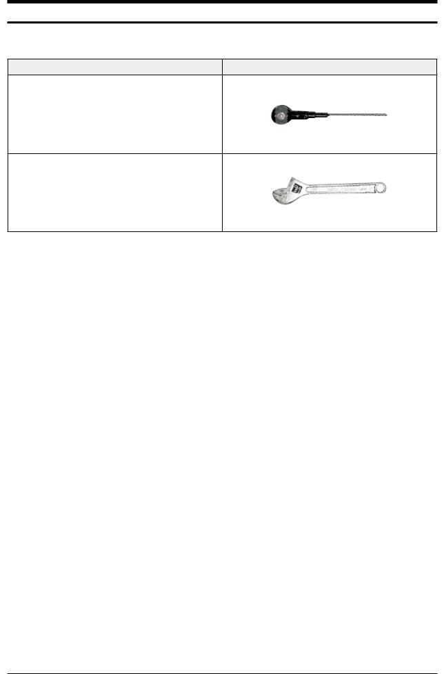
QNecessary Tools
Item |
Remark |
+SCREW DRIVER
MONKEY SPANNER
Samsung Electronics |
3-1 |

3-1 Indoor Unit
No |
Parts |
Procedure |
Remark |
|
|
|
|
1 |
PANEL-FRONT |
1) Stop the driving of air conditioner and shut off |
|
|
|
main power supply. |
|
|
|
2) Open the FRONT-GRILLE and pull out from the |
|
|
|
PANEL-FRONT. |
|
3)Detach COVER-TERMINAL from the PANELFRONT.(use + Screw Driver)
4)Loosen connector wire(white) and detach the temperature sensor wire.
5)To detach the FRONT-PANEL the main frame, unfasten 2 screw at the bottom.(use + Screw Driver)
6) Take off the FRONT-PANEL,lifting up the bottom.
3-2 |
Samsung Electronics |
Operating Instructions and Installation
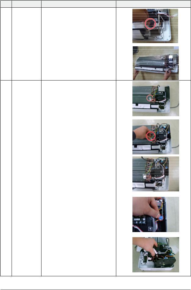
No |
Parts |
Procedure |
Remark |
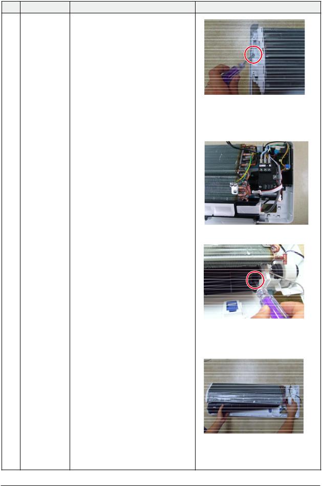
2TRAY DRAIN 1) Loosen stepping motor wire and detach the
hook of main frame.
2)To detach TRAY-DRAIN from the main frame, pull the bottom of the TRAY-DRAIN towards you.
3CONTROL IN 1) Unfasten the earth screw.(use + Screw Driver)
2)Detach the temperature sensor and Humidity sensor.
3)Detach COVER-CONTROL from the CASECONTROL.
4)Loosen MPI connector wire(yellow), and MOTOR wires(white,blue).
5)Take off the CASE-CONTROL from the main frame.
Samsung Electronics |
3-3 |
Operating Instructions and Installation
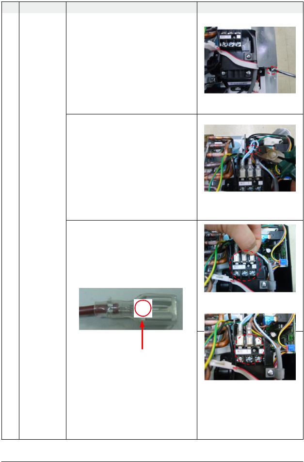
No |
Parts |
Procedure |
Remark |
|
|
|
|
4 |
PBA |
1) Unfasten the screw. |
|
2) Cut the cable tie.
3)Loosen the terminal block wires. (Total 4EA: #N(T)-2EA, #2-TEA, #3-TEA)
KCaution:
The terminal is locking type.
So, when you separate terminals, pull pressing the button.
Button
3-4 |
Samsung Electronics |
|
|
|
Operating Instructions and Installation |
|
|
|
|
No |
Parts |
Procedure |
Remark |
|
|
|
|
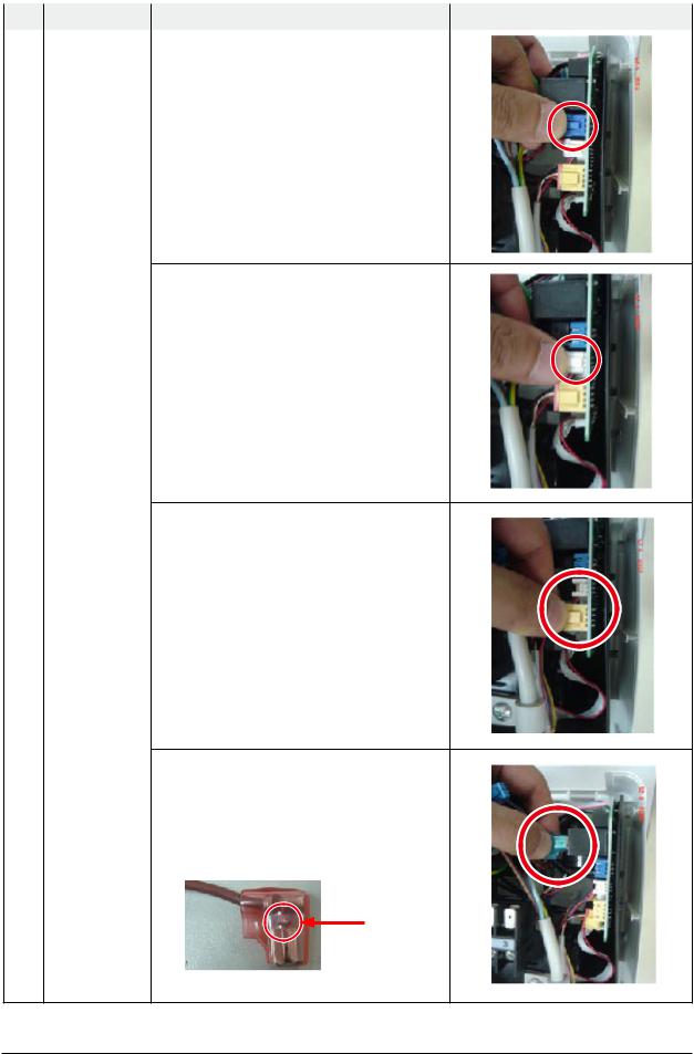
4 |
PBA |
4) Loosen the Motor Feedback connector(CN44). |
|
|
|
KCaution: |
|
|
|
When you separate the connector, |
|
|
|
pull pressing the locking button. |
|
5)Loosen the Humidity sensor connector(CN42). ¬Option connector.
KCaution:
When you separate the connector, pull pressing the locking button.
6)Loosen the MPI connector(CN81). ¬Option connector.
KCaution:
When you separate the connector, pull pressing the locking button.
7) Loosen the Relay #4 blue-connector(RY71).
KCaution:
The terminal is locking type.
So, when you separate terminals, pull pressing the button.
Button
Samsung Electronics |
3-5 |

Operating Instructions and Installation
No |
Parts |
Procedure |
Remark |
|
|
|
|
4 |
PBA |
8) Loosen the Relay #3 red-connector(RY71). |
|
|
|
KCaution: |
|
|
|
The terminal is locking type. |
|
|
|
So, when you separate terminals, |
|
|
|
pull pressing the button. |
|
Button
9) Loosen the Step motor connector.
KCaution:
When you separate the connector, pull pressing the locking button.
10) Loosen the Thermistor wire connector(CN43).
KCaution:
When you take off the PBA, don’t touch the components.
Please hold the PBA both side.
11) Loosen the Motor connector(CN71).
KCaution:
When you separate the connector, pull pressing the locking button.
3-6 |
Samsung Electronics |

|
|
|
Operating Instructions and Installation |
|
|
|
|
No |
Parts |
Procedure |
Remark |
|
|
|
|
4 |
PBA |
12) Take off the main PBA from the ASS’Y |
|
|
|
Control in. |
|
|
|
KCaution: |
|
|
|
When you take off the PBA, don’t touch |
|
|
|
the components. |
|
|
|
Please hold the PBA both side. |
|
|
|
|
|
Samsung Electronics |
3-7 |
Operating Instructions and Installation
No |
Parts |
Procedure |
Remark |
5EVAPORATOR 1) Unfasten the screw at the right side.
(use + Screw Driver)
2)Unfasten the screw at the left side. (use + Screw Driver)
3) Detach the HOLDER PIPE.
4)Take off the EVAPORATOR from the main frame.
3-8 |
Samsung Electronics |
Operating Instructions and Installation
No |
Parts |
Procedure |
Remark |
6FAN MOTOR 1) Unfasten the screw in the HOLDER-EVAP on the
&left side of evaporator.(use + Screw Driver)
CROSS FAN
2)unfasten the 3 points screws in the CASECONTROL, and then detach the CASE. (use + Screw Driver)
3) unfasten the screw a little.(use + Screw Driver)
4)Lift up the evaporator slightly and pull the CROSS-FAN to the left side.
Samsung Electronics |
3-9 |

Operating Instructions and Installation
3-2 Outdoor Unit
No |
Parts |
Procedure |
Remark |
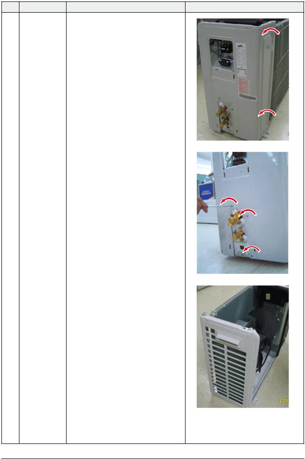
1Common Work 1) Loosen 1 fixing screw(CCW) of the Cover-Side.
(Use +Screw Driver.)
2)Loosen each 4 screws(CCW) on both right and left Cabinet Side edges and a fixing screw on the Cabinet Front lower to detach the Cabinet Front. (Use +Screw Driver.)
3) Detach the Cabinet Front like the picture on the right side.
4)Loosen 1 screw(CCW) fixed to assemble Plate Control Out with Cabinet-Side RH.
(Use +Screw Driver.)
3-10 |
Samsung Electronics |
Operating Instructions and Installation
No |
Parts |
Procedure |
Remark |
5) Loosen 2 fixing screws(CCW) on the rear side of Cabinet-Side RH. (Use +Screw Driver.)
6)Loosen 3 screws(CCW) fixed to assemble Bracket Valve with Cabinet-Side RH. (Use +Screw Driver.)
7)Loosen 2 fixing screws(CCW) of Cabinet Side LF. (Use +Screw Driver.)
Samsung Electronics |
3-11 |

Operating Instructions and Installation
No |
Parts |
Procedure |
Remark |
2Ass’y Control Out 1) Detach the Motor Wire from the PCB of Ass’y
Control Out.
2)Detach several connectors from the PCB of Ass’ y Control Out.
3) Detach 2 Connect Wires from Reactor.
4)Loosen 1 screw(CCW) fixed to assemble Ass’y Control Out with Partition.
(Use +Screw Driver.)
3-12 |
Samsung Electronics |
|
|
|
Operating Instructions and Installation |
|
|
|
|
No |
Parts |
Procedure |
Remark |
|
|
|
|
3 |
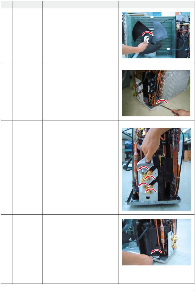
Fan |
1) Release the refrigerant at first. |
|
|
& |
2) Loosen fixing screw(CW). (Use Monkey |
|
Motor Spanner.)
3)Disassemble the pipes in both inlet and outlet with welding torch.
4)Detach the Heat Exchanger.
4Heat Exchanger 1) Loosen 2 fixing screws(CCW) on both sides.
(Use +Screw Driver.)
2)Disassemble the pipes in both inlet and outlet with welding torch.
3)Detach the Heat Exchanger.
 Before you disassemble the pipes and Condenser, be sure that there should be no refrigerant remained in the unit.
5Ass’y Valve 4-Way 1) Loosen 4 bolts(CCW) fixed to assemble Valve
&Service with Bracket Valve like the picture on Ass’y Valve EEV the right side. (Use Monkey Spanner.)
2)Disassemble the pipes assembled the suction and discharge sides of the Compressor with welding torch.
6Compressor 1) Loosen the Nut(CCW) of Terminal Cover. (Use
Monkey Spanner.)
2)Detach the Terminal Cover and detach the Connect Comp Wire from Compressor.
3)Disassemble the Felt Comp Sound.
4)Loosen the 3 bolts(CCW) at the bottom of Compressor like the picture on the right side. (Use Monkey Spanner.)
Samsung Electronics |
3-13 |

MEMO
3-14 |
Samsung Electronics |

Exploded Views and Parts List
Operating Instructions and Installation
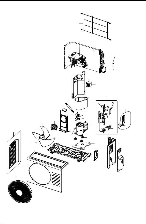
5. Exploded Views and Parts List
5-1 Indoor Unit
Samsung Electronics |
5-1 |

Exploded Views and Parts List
QParts List
No. |
Code No. |
Description |
Specification |
|
Q’TY |
SA/SNA |
||
AQV09UGAN |
AQV12UGAN |
|||||||
|
|
|
|
|
||||
|
|
|
|
|
|
|
|
|
1 |
DB94-01921B |
ASSY BACK BODY |
ASSY |
1 |
|
1 |
SA |
|
1-1 |
DB61-03656A |
BODY BACK |
HIPS |
1 |
|
1 |
SA |
|
1-2 |
DB61-03651A |
SUPPORT-EVAP RH |
HIPS |
1 |
|
1 |
SA |
|
1-3 |
DB62-05888A |
SEAL-INSUL BODY REAR |
EPS(30) |
1 |
|
1 |
SA |
|
1-4 |
DB61-03666A |
HOLDER-PIPE |
HIPS |
1 |
|
1 |
SA |
|
2 |
DB97-02851C |
ASSY-PLATE HANGER |
SGCC-M, T0.7 |
1 |
|
1 |
SA |
|
3 |
DB92-01406N |
ASSY PANEL FRONT |
ASSY |
1 |
|
1 |
SA |
|
3-1 |
DB64-02124A |
PANEL FRONT |
HIPS |
1 |
|
1 |
SA |
|
3-2 |
DB63-02143A |
FILTER-PRE L |
PP |
1 |
|
1 |
SA |
|
3-3 |
DB63-02144A |
FILTER-PRE R |
PP |
1 |
|
1 |
SA |
|
3-4 |
DB90-04375A |
ASSY CASE-PCB |
|
1 |
|
1 |
SA |
|
3-5 |
DB63-02120A |
COVER TERMINAL |
HIPS(5V) |
1 |
|
1 |
SA |
|
3-6 |
DB90-04305E |
ASSY COVER DISPLAY |
ASSY |
1 |
|
1 |
SA |
|
3-7 |
DB64-02127A |
GRILLE-AIR INLET |
HIPS |
1 |
|
1 |
SA |
|
3-8 |
DB81-01288B |
DECO-GRILLE |
HIPS |
1 |
|
1 |
SA |
|
4 |
DB93-06996B |
ASSY CONTROL IN |
ASSY |
1 |
|
1 |
SA |
|
5 |
DB90-04385A |
ASSY COVER CONTROL IN |
T0.5 |
1 |
|
1 |
SA |
|
6 |
DB94-01922A |
ASSY TRAY DRAIN |
ASSY |
1 |
|
1 |
SA |
|
6-1 |
DB63-02118A |
TRAY DRAIN |
ABS |
1 |
|
1 |
SA |
|
6-2 |
DB61-03672A |
BLADE-V |
PP |
2 |
|
2 |
SA |
|
6-3 |
DB61-03649A |
BLADE-H |
ABS |
1 |
|
1 |
SA |
|
6-4 |
DB62-05892A |
INSULATION-TRAY FR |
EPS(30) |
1 |
|
1 |
SA |
|
6-5 |
DB31-00371A |
MOTOR STEP |
DC12V,600gf.cm |
1 |
|
1 |
SA |
|
6-6 |
DB69-00839A |
CUSHION-TRAY RH |
EPS(30) |
1 |
|
1 |
SA |
|
6-7 |
DB63-02121A |
TRAY-STABILIZER |
HIPS |
1 |
|
1 |
SA |
|
6-8 |
DB94-01975A |
ASSY DRAIN-HOSE |
ASSY |
1 |
|
1 |
SA |
|
7 |
DB96-11360A |
ASSY EVAP TOTAL |
ASSY |
1 |
|
- |
SA |
|
DB96-11359A |
ASSY EVAP TOTAL |
ASSY |
- |
|
1 |
SA |
||
|
|
|||||||
7-1 |
DB61-03650A |
HOLDER-EVAP |
HIPS |
1 |
|
1 |
SA |
|
8 |
DB94-01874A |
ASSY-CROSS FAN |
ASSY ; AS +GF20% |
1 |
|
1 |
SA |
|
9 |
DB31-00531A |
MOTOR FAN |
- |
1 |
|
1 |
SA |
|
5-2 |
Samsung Electronics |

Exploded Views and Parts List
5-2 Outdoor Unit
|
|
|
|
|
|
|
|
|
|
|
|
|
|
|
|
|
|
|
|
|
|
|
|
|
|
|
|
|
|
|
|
|
|
|
|
|
|
|
|
|
|
|
|
|
|
|
|
|
|
|
|
|
|
|
|
|
|
|
|
|
|
|
|
|
|
|
|
|
|
|
|
Samsung Electronics |
5-3 |
Exploded Views and Parts List
QParts List
|
|
|
|
Q'TY |
|
|
No. |
Code No. |
Description |
Specification |
AQV09UGAX |
AQV12UGAX |
SA/SNA |
|
|
|
|
|
|
|
1 |
DB90-03870H |
ASS’Y CABI FRONT |
ASS’Y,SC-94445T |
1 |
1 |
SA |
2 |
DB63-02004A |
GUARD FAN |
HIPS,SC-90073R |
1 |
1 |
SA |
|
|
|
|
|
|
|
3 |
DB90-01330L |
ASS’Y BASE OUT |
ASS’Y,SC-94445T |
1 |
1 |
SA |
4 |
DB99-00401B |
ASS’Y BRACKET VALVE |
ASS’Y,SC-94445T |
1 |
1 |
SA |
5 |
DB67-00397A |
FAN-PROPELLER |
AS+G/F20%,ø400 |
1 |
1 |
SA |
6 |
DB60-30028A |
NUT-HEXAGON |
M6 |
1 |
1 |
SA |
7 |
DB31-00220B |
MOTOR FAN OUT |
AC Motor |
1 |
1 |
SA |
8 |
DB61-01644A |
BRACKET MOTOR |
SGCC-M |
1 |
1 |
SA |
|
|
|
|
|
|
|
9 |
DB97-02225J |
ASS’Y SUPPORT PLATE B/M |
SGCC-M |
1 |
1 |
SA |
10 |
DB94-01180D |
ASS’Y PARTITION |
ASS’Y,SGCC-M |
1 |
1 |
SA |
11 |
DB27-00041A |
REACTOR |
PPS,5mH,10A |
1 |
1 |
SA |
|
|
|
|
|
|
|
12 |
DB96-06562D |
ASS’Y COND UNIT |
ASS’Y |
1 |
- |
SA |
|
DB96-06562D |
ASS’Y COND UNIT |
ASS’Y |
- |
1 |
SA |
13 |
DB90-03818D |
COVER CONTROL |
ASS’Y |
1 |
1 |
SA |
|
|
|
|
|
|
|
14 |
DB90-01546Q |
ASS’Y CABINET SIDE RH |
ASS’Y,SC-94445T |
1 |
1 |
SA |
15 |
DB90-01332C |
ASS’Y CABINET SIDE LF |
SECC-P,SC-94445T |
1 |
1 |
SA |
17 |
G4C090LUDER |
COMPRESSOR |
ROTARY,BLDC |
1 |
1 |
SA |
17-1 |
DB63-02036A |
GROMMET ISOLATOR |
NR |
3 |
3 |
SNA |
17-2 |
DB60-30028A |
SCREW HEX |
M8 |
3 |
3 |
SNA |
17-3 |
DB60-30004A |
SCREW MACHINE |
M5 |
1 |
1 |
SNA |
17-4 |
DB63-00816A |
COVER TERMINAL |
PBT(G/F 15%) |
1 |
1 |
SNA |
17-5 |
DB63-00817A |
GASKET |
EPDM |
1 |
1 |
SNA |
18 |
DB63-01647A |
FELT COMP SIDE |
FELT+PVC Sheet |
1 |
1 |
SA |
19 |
DB63-01950A |
FELT COMP BASE |
FELT+PVC Sheet |
1 |
1 |
SA |
|
DB63-01710B |
FELT COMP UPPER |
FELT+PVC Sheet |
1 |
1 |
SA |
|
DB63-02033C |
FELT COMP SIDE OUT |
FELT+PVC Sheet |
1 |
1 |
SA |
|
DB63-02034A |
FELT COMP UPPER OUT |
FELT+PVC Sheet |
1 |
1 |
SA |
|
|
|
|
|
|
|
20 |
DB99-00967B |
ASS’Y VALVE 4WAY |
ASS’Y |
1 |
1 |
SA |
20-1 |
DB62-02286A |
4WAY VALVE |
R410A,SANHUA |
1 |
1 |
SNA |
20-2 |
DB62-02284A |
VALVE SERVICE |
R410A,SANHUA,3/8” |
1 |
1 |
SNA |
|
|
|
|
|
|
|
21 |
DB99-00968A |
ASSY-VALVE CHECK |
ASS’Y |
1 |
- |
SA |
|
DB99-00968A |
ASSY-VALVE CHECK |
ASS’Y |
- |
1 |
SA |
|
|
|
|
|
|
|
21-2 |
DB62-02283A |
VALVE SERVICE |
R410A,SANHUA,1/4” |
1 |
1 |
SNA |
|
|
|
|
|
|
|
22 |
DB93-07024C |
ASS’Y CONTROL OUT |
ASS’Y |
1 |
- |
SA |
|
DB93-07024D |
ASS’Y CONTROL OUT |
ASS’Y |
- |
1 |
SA |
23 |
DB64-02117B |
SCREEN COND BAR |
P.E.H 100% |
1 |
1 |
SA |
24 |
DB95-01358B |
THERMISTOR |
ASS’Y |
1 |
1 |
SA |
25 |
DB93-07548A |
CONNECT WIRE COMP |
ASS’Y |
1 |
1 |
SA |
5-4 |
Samsung Electronics |

Exploded Views and Parts List
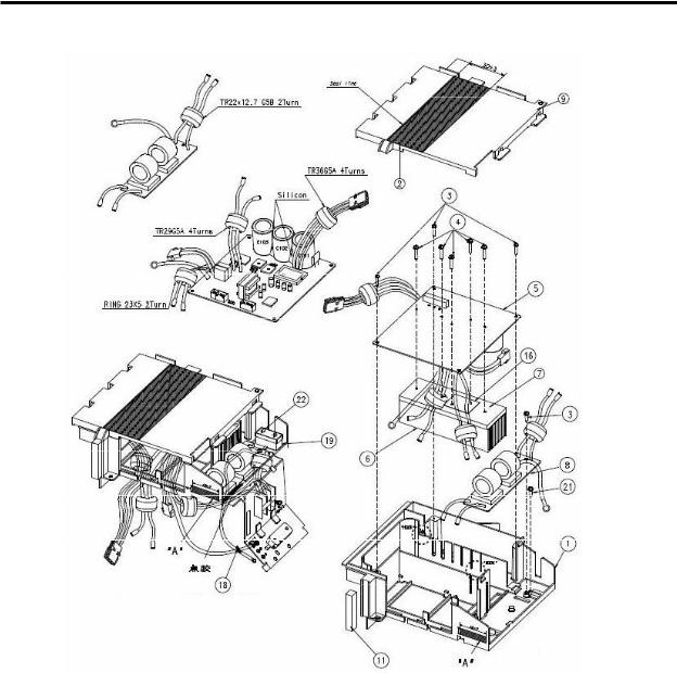
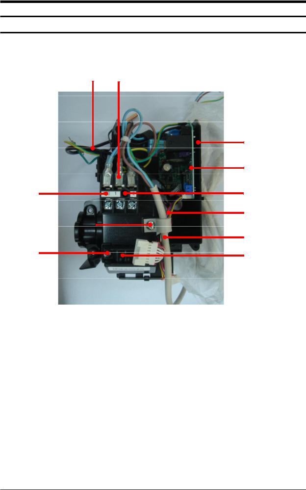
5-3 Ass'y Control Out
Ŷ$49 8*$; '% &
$49 8*$; '% '
|
NO. |
&2'( |
'(6&5,37,21 |
47< |
|
|
|
|
|
|
'% & |
'% ' |
|
|
1 |
'% $ |
&$6( &21752/ %$6( |
1 |
1 |
|
|
2 |
'% $ |
6($/ &$6( &21752/ &29(5 |
1 |
1 |
|
|
3 |
|
6&5(: |
4 |
4 |
|
|
4 |
'% $ |
$66< 6&5(: 0$&+,1( |
5 |
5 |
|
|
5 |
'% & |
$66< 3&% 287 |
1 |
0 |
|
|
|
'% ' |
$66< 3&% 287 |
0 |
1 |
|
|
6 |
'% $ |
+($7 6,1. |
1 |
1 |
|
|
7 |
'% $ |
7+(50$/ *5($6( |
0.002 |
0.002 |
|
|
8 |
'% $ |
$66< 3&% (0, |
1 |
1 |
|
|
9 |
'% $ |
&$6( &21752/ &29(5 |
1 |
1 |
|
|
10 |
'% $ |
3/$7( &21752/ 287 |
1 |
1 |
|
|
11 |
'% 3 |
6($/ &$6( &21752/ |
1 |
1 |
|
|
12 |
|
6&5(: 7$33,1* |
1 |
1 |
|
|
13 |
'% % |
7(50,1$/ %/2&. |
1 |
1 |
|
|
14 |
'% $ |
+2/'(5 :,5( &/$03 |
1 |
1 |
|
|
15 |
|
6&5(: 7$33,1* |
2 |
2 |
|
|
16 |
'% % |
,168/$725 .)5 |
1 |
1 |
|
|
17 |
|
6&5(: |
2 |
2 |
|
|
18 |
'% ' |
&$%/( 7,( |
1 |
1 |
|
|
19 |
|
& ),/0 /($' 27+(5 |
1 |
1 |
|
|
20 |
|
6&5(: 0$&+,1( |
1 |
1 |
|
|
21 |
|
6&5(: 7$33,1* |
1 |
1 |
|
|
22 |
'% $ |
58%%(5 &$3$&7,25 |
1 |
1 |
|
Samsung Electronics |
5-5 |

Exploded Views and Parts List
Operating Instructions and Installation
5. Exploded Views and Parts List
5-1 Indoor Unit
Samsung Electronics |
5-1 |

Exploded Views and Parts List
QParts List
No. |
Code No. |
Description |
Specification |
|
Q’TY |
SA/SNA |
||
AQV09UGAN |
AQV12UGAN |
|||||||
|
|
|
|
|
||||
|
|
|
|
|
|
|
|
|
1 |
DB94-01921B |
ASSY BACK BODY |
ASSY |
1 |
|
1 |
SA |
|
1-1 |
DB61-03656A |
BODY BACK |
HIPS |
1 |
|
1 |
SA |
|
1-2 |
DB61-03651A |
SUPPORT-EVAP RH |
HIPS |
1 |
|
1 |
SA |
|
1-3 |
DB62-05888A |
SEAL-INSUL BODY REAR |
EPS(30) |
1 |
|
1 |
SA |
|
1-4 |
DB61-03666A |
HOLDER-PIPE |
HIPS |
1 |
|
1 |
SA |
|
2 |
DB97-02851C |
ASSY-PLATE HANGER |
SGCC-M, T0.7 |
1 |
|
1 |
SA |
|
3 |
DB92-01406N |
ASSY PANEL FRONT |
ASSY |
1 |
|
1 |
SA |
|
3-1 |
DB64-02124A |
PANEL FRONT |
HIPS |
1 |
|
1 |
SA |
|
3-2 |
DB63-02143A |
FILTER-PRE L |
PP |
1 |
|
1 |
SA |
|
3-3 |
DB63-02144A |
FILTER-PRE R |
PP |
1 |
|
1 |
SA |
|
3-4 |
DB90-04375A |
ASSY CASE-PCB |
|
1 |
|
1 |
SA |
|
3-5 |
DB63-02120A |
COVER TERMINAL |
HIPS(5V) |
1 |
|
1 |
SA |
|
3-6 |
DB90-04305E |
ASSY COVER DISPLAY |
ASSY |
1 |
|
1 |
SA |
|
3-7 |
DB64-02127A |
GRILLE-AIR INLET |
HIPS |
1 |
|
1 |
SA |
|
3-8 |
DB81-01288B |
DECO-GRILLE |
HIPS |
1 |
|
1 |
SA |
|
4 |
DB93-06996B |
ASSY CONTROL IN |
ASSY |
1 |
|
1 |
SA |
|
5 |
DB90-04385A |
ASSY COVER CONTROL IN |
T0.5 |
1 |
|
1 |
SA |
|
6 |
DB94-01922A |
ASSY TRAY DRAIN |
ASSY |
1 |
|
1 |
SA |
|
6-1 |
DB63-02118A |
TRAY DRAIN |
ABS |
1 |
|
1 |
SA |
|
6-2 |
DB61-03672A |
BLADE-V |
PP |
2 |
|
2 |
SA |
|
6-3 |
DB61-03649A |
BLADE-H |
ABS |
1 |
|
1 |
SA |
|
6-4 |
DB62-05892A |
INSULATION-TRAY FR |
EPS(30) |
1 |
|
1 |
SA |
|
6-5 |
DB31-00371A |
MOTOR STEP |
DC12V,600gf.cm |
1 |
|
1 |
SA |
|
6-6 |
DB69-00839A |
CUSHION-TRAY RH |
EPS(30) |
1 |
|
1 |
SA |
|
6-7 |
DB63-02121A |
TRAY-STABILIZER |
HIPS |
1 |
|
1 |
SA |
|
6-8 |
DB94-01975A |
ASSY DRAIN-HOSE |
ASSY |
1 |
|
1 |
SA |
|
7 |
DB96-11360A |
ASSY EVAP TOTAL |
ASSY |
1 |
|
- |
SA |
|
DB96-11359A |
ASSY EVAP TOTAL |
ASSY |
- |
|
1 |
SA |
||
|
|
|||||||
7-1 |
DB61-03650A |
HOLDER-EVAP |
HIPS |
1 |
|
1 |
SA |
|
8 |
DB94-01874A |
ASSY-CROSS FAN |
ASSY ; AS +GF20% |
1 |
|
1 |
SA |
|
9 |
DB31-00531A |
MOTOR FAN |
- |
1 |
|
1 |
SA |
|
5-2 |
Samsung Electronics |
Exploded Views and Parts List
5-2 Outdoor Unit
|
|
|
|
|
|
|
|
|
|
|
|
|
|
|
|
|
|
|
|
|
|
|
|
|
|
|
|
|
|
|
|
|
|
|
|
|
|
|
|
|
|
|
|
|
|
|
|
|
|
|
|
|
|
|
|
|
|
|
|
|
|
|
|
|
|
|
|
|
|
|
|
Samsung Electronics |
5-3 |

Exploded Views and Parts List
QParts List
|
|
|
|
Q'TY |
|
|
No. |
Code No. |
Description |
Specification |
AQV09UGAX |
AQV12UGAX |
SA/SNA |
|
|
|
|
|
|
|
1 |
DB90-03870H |
ASS’Y CABI FRONT |
ASS’Y,SC-94445T |
1 |
1 |
SA |
2 |
DB63-02004A |
GUARD FAN |
HIPS,SC-90073R |
1 |
1 |
SA |
|
|
|
|
|
|
|
3 |
DB90-01330L |
ASS’Y BASE OUT |
ASS’Y,SC-94445T |
1 |
1 |
SA |
4 |
DB99-00401B |
ASS’Y BRACKET VALVE |
ASS’Y,SC-94445T |
1 |
1 |
SA |
5 |
DB67-00397A |
FAN-PROPELLER |
AS+G/F20%,ø400 |
1 |
1 |
SA |
6 |
DB60-30028A |
NUT-HEXAGON |
M6 |
1 |
1 |
SA |
7 |
DB31-00220B |
MOTOR FAN OUT |
AC Motor |
1 |
1 |
SA |
8 |
DB61-01644A |
BRACKET MOTOR |
SGCC-M |
1 |
1 |
SA |
|
|
|
|
|
|
|
9 |
DB97-02225J |
ASS’Y SUPPORT PLATE B/M |
SGCC-M |
1 |
1 |
SA |
10 |
DB94-01180D |
ASS’Y PARTITION |
ASS’Y,SGCC-M |
1 |
1 |
SA |
11 |
DB27-00041A |
REACTOR |
PPS,5mH,10A |
1 |
1 |
SA |
|
|
|
|
|
|
|
12 |
DB96-06562D |
ASS’Y COND UNIT |
ASS’Y |
1 |
- |
SA |
|
DB96-06562D |
ASS’Y COND UNIT |
ASS’Y |
- |
1 |
SA |
13 |
DB90-03818D |
COVER CONTROL |
ASS’Y |
1 |
1 |
SA |
|
|
|
|
|
|
|
14 |
DB90-01546Q |
ASS’Y CABINET SIDE RH |
ASS’Y,SC-94445T |
1 |
1 |
SA |
15 |
DB90-01332C |
ASS’Y CABINET SIDE LF |
SECC-P,SC-94445T |
1 |
1 |
SA |
17 |
G4C090LUDER |
COMPRESSOR |
ROTARY,BLDC |
1 |
1 |
SA |
17-1 |
DB63-02036A |
GROMMET ISOLATOR |
NR |
3 |
3 |
SNA |
17-2 |
DB60-30028A |
SCREW HEX |
M8 |
3 |
3 |
SNA |
17-3 |
DB60-30004A |
SCREW MACHINE |
M5 |
1 |
1 |
SNA |
17-4 |
DB63-00816A |
COVER TERMINAL |
PBT(G/F 15%) |
1 |
1 |
SNA |
17-5 |
DB63-00817A |
GASKET |
EPDM |
1 |
1 |
SNA |
18 |
DB63-01647A |
FELT COMP SIDE |
FELT+PVC Sheet |
1 |
1 |
SA |
19 |
DB63-01950A |
FELT COMP BASE |
FELT+PVC Sheet |
1 |
1 |
SA |
|
DB63-01710B |
FELT COMP UPPER |
FELT+PVC Sheet |
1 |
1 |
SA |
|
DB63-02033C |
FELT COMP SIDE OUT |
FELT+PVC Sheet |
1 |
1 |
SA |
|
DB63-02034A |
FELT COMP UPPER OUT |
FELT+PVC Sheet |
1 |
1 |
SA |
|
|
|
|
|
|
|
20 |
DB99-00967B |
ASS’Y VALVE 4WAY |
ASS’Y |
1 |
1 |
SA |
20-1 |
DB62-02286A |
4WAY VALVE |
R410A,SANHUA |
1 |
1 |
SNA |
20-2 |
DB62-02284A |
VALVE SERVICE |
R410A,SANHUA,3/8” |
1 |
1 |
SNA |
|
|
|
|
|
|
|
21 |
DB99-00968A |
ASSY-VALVE CHECK |
ASS’Y |
1 |
- |
SA |
|
DB99-00968A |
ASSY-VALVE CHECK |
ASS’Y |
- |
1 |
SA |
|
|
|
|
|
|
|
21-2 |
DB62-02283A |
VALVE SERVICE |
R410A,SANHUA,1/4” |
1 |
1 |
SNA |
|
|
|
|
|
|
|
22 |
DB93-07024C |
ASS’Y CONTROL OUT |
ASS’Y |
1 |
- |
SA |
|
DB93-07024D |
ASS’Y CONTROL OUT |
ASS’Y |
- |
1 |
SA |
23 |
DB64-02117B |
SCREEN COND BAR |
P.E.H 100% |
1 |
1 |
SA |
24 |
DB95-01358B |
THERMISTOR |
ASS’Y |
1 |
1 |
SA |
25 |
DB93-07548A |
CONNECT WIRE COMP |
ASS’Y |
1 |
1 |
SA |
5-4 |
Samsung Electronics |
Exploded Views and Parts List
5-3 Ass'y Control Out
Ŷ$49 8*$; '% &
$49 8*$; '% '
|
NO. |
&2'( |
'(6&5,37,21 |
47< |
|
|
|
|
|
|
'% & |
'% ' |
|
|
1 |
'% $ |
&$6( &21752/ %$6( |
1 |
1 |
|
|
2 |
'% $ |
6($/ &$6( &21752/ &29(5 |
1 |
1 |
|
|
3 |
|
6&5(: |
4 |
4 |
|
|
4 |
'% $ |
$66< 6&5(: 0$&+,1( |
5 |
5 |
|
|
5 |
'% & |
$66< 3&% 287 |
1 |
0 |
|
|
|
'% ' |
$66< 3&% 287 |
0 |
1 |
|
|
6 |
'% $ |
+($7 6,1. |
1 |
1 |
|
|
7 |
'% $ |
7+(50$/ *5($6( |
0.002 |
0.002 |
|
|
8 |
'% $ |
$66< 3&% (0, |
1 |
1 |
|
|
9 |
'% $ |
&$6( &21752/ &29(5 |
1 |
1 |
|
|
10 |
'% $ |
3/$7( &21752/ 287 |
1 |
1 |
|
|
11 |
'% 3 |
6($/ &$6( &21752/ |
1 |
1 |
|
|
12 |
|
6&5(: 7$33,1* |
1 |
1 |
|
|
13 |
'% % |
7(50,1$/ %/2&. |
1 |
1 |
|
|
14 |
'% $ |
+2/'(5 :,5( &/$03 |
1 |
1 |
|
|
15 |
|
6&5(: 7$33,1* |
2 |
2 |
|
|
16 |
'% % |
,168/$725 .)5 |
1 |
1 |
|
|
17 |
|
6&5(: |
2 |
2 |
|
|
18 |
'% ' |
&$%/( 7,( |
1 |
1 |
|
|
19 |
|
& ),/0 /($' 27+(5 |
1 |
1 |
|
|
20 |
|
6&5(: 0$&+,1( |
1 |
1 |
|
|
21 |
|
6&5(: 7$33,1* |
1 |
1 |
|
|
22 |
'% $ |
58%%(5 &$3$&7,25 |
1 |
1 |
|
Samsung Electronics |
5-5 |
6. PCB Diagram and Parts List
6-1. Block Diagram
6-1-1. Ass'y Control In : DB93-06996B
|
|
|
|
|
|
|
|
|
|
|
|
|
|
|
|
|
|
|
|
|
|
|
|
NO. |
&2'( |
|
'(6&5,37,21 |
47< |
|
1 |
'% $ |
&$6( &21752/ ,1 |
1 |
|
|
2 |
'% % |
$66< 3&% 0$,1 |
1 |
|
|
3 |
'% $ |
+2/'(5 :,5( &/$03 |
1 |
|
|
4 |
'% $ |
6&5(: |
1 |
|
|
5 |
'% $ |
6&5(: |
3 |
|
|
6 |
'% $ |
$66< 32:(5 &25' |
1 |
|
|
7 |
'% ) |
$66< 7+(50,6725 |
1 |
|
|
8 |
'% $ |
$66< & : 7 % 72 5< |
1 |
|
|
9 |
'% $ |
$66< & : /289(5 |
1 |
|
|
10 |
'% % |
7(50,1$/ %/2&. |
1 |
|
|
Samsung Electronics |
6-1 |
 Loading...