


DIGITAL 31 BAND REAL TIME ANALYZER
������������������

WARNING:To reduce the risk of fire or electric shock, do not expose this unit to rain or moisture.To reduce the hazard of electrical shock, do not remove cover or back. No user serviceable parts inside. Please refer all servicing to qualified personnel.The lightning flash with an arrowhead symbol within an equilateral triangle, is intended to alert the user to the presence of uninsulated "dangerous voltage" within the products enclosure that may be of sufficient magnitude to constitute a risk of electric shock to persons.The exclamation point within an equilateral triangle is intended to alert the user to the presence of important operating and maintenance (servicing) instructions in the literature accompanying the product.
Important Safety Instructions
1.Please read all instructions before operating the unit.
2.Keep these instructions for future reference.
3.Please heed all safety warnings.
4.Follow manufacturers instructions.
5.Do not use this unit near water or moisture.
6.Clean only with a damp cloth.
7.Do not block any of the ventilation openings. Install in accordance with the manufacturers instructions.
8.Do not install near any heat sources such as radiators, heat registers, stoves, or other apparatus (including amplifiers) that produce heat.
9.Do not defeat the safety purpose of the polarized or grounding-type plug. A polarized plug has two blades with one wider than the other. A grounding type plug has two blades and a third grounding prong.The wide blade or third prong is provided for your safety.When the provided plug does not fit your outlet, consult an electrician for replacement of the obsolete outlet.
10.Protect the power cord from being walked on and pinched particularly at plugs, convenience receptacles and at the point at which they exit from the unit.
11.Unplug this unit during lightning storms or when unused for long periods of time.
12.Refer all servicing to qualified personnel. Servicing is required when the unit has been damaged in any way, such as power supply cord or plug damage, or if liquid has been spilled or objects have fallen into the unit, the unit has been exposed to rain or moisture, does not operate normally, or has been dropped.
ACHTUNG: Um die Gefahr eines Brandes oder Stromschlags zu verringern, sollten Sie dieses Gerät weder Regen noch Feuchtigkeit aussetzen.Um die Gefahr eines Stromschlags zu verringern, sollten Sie weder Deckel noch Rückwand des Geräts entfernen. Im Innern befinden sich keineTeile, die vom Anwender gewartet werden kön-
nen. Überlassen Sie dieWartung qualifiziertem Fachpersonal.Der Blitz mit Pfeilspitze im gleichseitigen Dreieck soll den Anwender vor nichtisolierter“gefährlicher Spannung” im Geräteinnern warnen. Diese Spannung kann so hoch sein, dass die Gefahr eines Stromschlags besteht. Das Ausrufezeichen im gleichseitigen Dreieck soll den Anwender auf wichtige BedienungsundWartungsanleitungen aufmerksam machen, die im mitgelieferten Informationsmaterial näher beschrieben werden.
Wichtige Sicherheitsvorkehrungen
1.Lesen Sie alle Anleitungen, bevor Sie das Gerät in Betrieb nehmen.
2.Bewahren Sie diese Anleitungen für den späteren Gebrauch gut auf.
3.Bitte treffen Sie alle beschriebenen Sicherheitsvorkehrungen.
4.Befolgen Sie die Anleitungen des Herstellers.
5.Benutzen Sie das Gerät nicht in der Nähe vonWasser oder Feuchtigkeit.
6.Verwenden Sie zur Reinigung des Geräts nur ein feuchtesTuch.
7.Blockieren Sie keine Belüftungsöffnungen. Nehmen Sie den Einbau des Geräts nur entsprechend den Anweisungen des Herstellers vor.
8.Bauen Sie das Gerät nicht in der Nähe vonWärmequellen wie Heizkörpern,
Wärmeklappen, Öfen oder anderen Geräten (inklusiveVerstärkern) ein, die Hitze erzeugen.
9.Setzen Sie die Sicherheitsfunktion des polarisierten oder geerdeten Steckers nicht außer Kraft. Ein polarisierter Stecker hat zwei flache, unterschiedlich breite Pole. Ein geerdeter Stecker hat zwei flache Pole und einen dritten Erdungsstift. Der breitere Pol oder der dritte Stift dient Ihrer Sicherheit.Wenn der vorhandene Stecker nicht in Ihre Steckdose passt, lassen Sie die veraltete Steckdose von einem Elektriker ersetzen.
10.Schützen Sie das Netzkabel dahingehend, dass niemand darüber laufen und es nicht geknickt werden kann. Achten Sie hierbei besonders auf Netzstecker, Mehrfachsteckdosen und den Kabelanschluss am Gerät.
11.Ziehen Sie den Netzstecker des Geräts bei Gewittern oder längeren Betriebspausen aus der Steckdose.
12.Überlassen Sie dieWartung qualifiziertem Fachpersonal. EineWartung ist notwendig, wenn das Gerät auf irgendeineWeise, beispielsweise am Kabel oder Netzstecker beschädigt wurde, oder wenn Flüssigkeiten oder Objekte in das Gerät gelangt sind, es Regen oder Feuchtigkeit ausgesetzt war, nicht mehr wie gewohnt betrieben werden kann oder fallen gelassen wurde.
ATTENTION: Pour éviter tout risque d’électrocution ou d’incendie, ne pas exposer cet appareil à la pluie ou à l’humidité. Pourévitertoutrisqued’électrocution,nepasôterle couvercleouledosduboîtier. Cet appareil ne contient aucune pièce remplaçable par l'utilisateur. Confiez toutes les réparations à un personnel qualifié. Le signe avec un éclair dans un triangle prévient l’utilisateur de la présence d’une tension dangereuse et non isolée dans l’appareil. Cette tension constitue un risque d’électrocution. Le signe avec un point d’exclamation dans un triangle prévient l’utilisateur d’instructions importantes relatives à l’utilisation et à la maintenance du produit.
Consignes de sécurité importantes
1.Veuillez lire toutes les instructions avant d’utiliser l’appareil.
2.Conserver ces instructions pour toute lecture ultérieure.
3.Lisez avec attention toutes les consignes de sécurité.
4.Suivez les instructions du fabricant.
5.Ne pas utiliser cet appareil près d’une source liquide ou dans un lieu humide.
6.Nettoyez l’appareil uniquement avec un tissu humide.
7.Veillez à ne pas obstruer les fentes prévues pour la ventilation de l’appareil. Installez l’appareil selon les instructions du fabricant.
8.Ne pas installer près d’une source de chaleur (radiateurs, etc.) ou de tout équipement susceptible de générer de la chaleur (amplificateurs de puissance par exemple).
9.Ne pas retirer la terre du cordon secteur ou de la prise murale. Les fiches canadiennes avec polarisation (avec une lame plus large) ne doivent pas être modifiées. Si votre prise murale ne correspond pas au modèle fourni, consultez votre électricien.
10.Protégez le cordon secteur contre tous les dommages possibles (pincement, tension, torsion,, etc.).Veillez à ce que le cordon secteur soit libre, en particulier à sa sortie du boîtier.
11.Déconnectez l’appareil du secteur en présence d’orage ou lors de périodes d’inutilisation prolongées.
12.Consultez un service de réparation qualifié pour tout dysfonctionnement (dommage sur le cordon secteur, baisse de performances, exposition à la pluie, projection liquide dans l’appareil, introduction d’un objet dans le boîtier, etc.).
PRECAUCION: Para reducir el riesgo de incendios o descargas, no permita que este aparato quede expuesto a la lluvia o la humedad. Para reducir el riesgo de descarga eléctrica, nunca quite la tapa ni el chasis. Dentro del aparato no hay piezas susceptibles de ser reparadas por el usuario. Dirija cualquier reparación al servicio técnico oficial. El símbolo del relámpago dentro del triángulo equilátero pretende advertir al usuario de la presencia de“voltajes peligrosos”no aislados dentro de la carcasa del producto, que pueden ser de la magnitud suficiente como para constituir un riesgo de descarga eléctrica a las personas. El símbolo de exclamación dentro del triángulo equilátero quiere advertirle de la existencia de importantes instrucciones de manejo y mantenimiento (reparaciones) en los documentos que se adjuntan con este aparato.
Instrucciones importantes de seguridad
1.Lea todo este manual de instrucciones antes de comenzar a usar la unidad.
2.Conserve estas instrucciones para cualquier consulta en el futuro.
3.Cumpla con todo lo indicado en las precauciones de seguridad.
4.Observe y siga todas las instrucciones del fabricante.
5.Nunca utilice este aparato cerca del agua o en lugares húmedos.
6.Limpie este aparato solo con un trapo suave y ligeramente humedecido.
7.No bloquee ninguna de las aberturas de ventilación. Instale este aparato de acuerdo a las instrucciones del fabricante.
8.No instale este aparato cerca de fuentes de calor como radiadores, calentadores, hornos u otros aparatos (incluyendo amplificadores) que produzcan calor.
9.No anule el sistema de seguridad del enchufe de tipo polarizado o con toma de tierra. Un enchufe polarizado tiene dos bornes, uno más ancho que el otro. Uno con toma de tierra tiene dos bornes normales y un tercero para la conexión a tierra. El borne ancho o el tercero se incluyen como medida de seguridad. Cuando el enchufe no encaje en su salida de corriente, llame a un electricista para que le cambie su salida anticuada.
10.Evite que el cable de corriente quede en una posición en la que pueda ser pisado o aplastado, especialmente en los enchufes, receptáculos y en el punto en el que salen de la unidad.
11.Desconecte de la corriente este aparato durante las tormentas eléctricas o cuando no lo vaya a usar durante un periodo de tiempo largo.
12.Dirija cualquier posible reparación solo al servicio técnico oficial. Deberá hacer que su aparato sea reparado cuando esté dañado de alguna forma, como si el cable de corriente o el enchufe están dañados, o si se han derramado líquidos o se ha introducido algún objeto dentro de la unidad, si esta ha quedado expuesta a la lluvia o la humedad, si no funciona normalmente o si ha caído al suelo.

Table Of Contents |
|
ntroduction |
2 |
Controls And F ctions |
4 |
Front Panel Layout |
4 |
Rear Panel Layout |
5 |
D1500 Quick Start |
6 |
UsingThe D1500 As An Rta |
6 |
Global |
6 |
SelectingThe I put |
6 |
D1500 Quick Start |
7 |
UsingThe Microphone I put |
7 |
OperatingThe D1500 |
8 |
AdjustingThe Rta Parameters |
8 |
Source |
8 |
Gain |
8 |
Detect |
8 |
Integ – Integration |
8 |
Weight |
8 |
Ref - Reference Level |
9 |
Res – Resolution |
9 |
Hold |
9 |
Freq – Frequency |
9 |
UsingThe Analyze Mode |
9 |
UsingThe D1500’s Eq Display |
1 0 |
OperatingThe Phase Meter |
0 |
UsingThe D1500 As AVu Meter |
0 |
UsingThe D1500 As A Signal Generator |
|
Storing Programs InThe D1500 |
2 |
Loading Programs InThe D1500 |
2 |
Midi And D Net |
3 |
OperatingThe D1500WithThe D2500 Digital Eq |
5 |
Using The D1500WithThe D2500 |
5 |
OperatingThe D1500WithThe D2500 Digital Eq |
6 |
UsingThe D1500’s Eq Display |
1 6 |
UsingThe Signal Generator |
7 |
OperatingThe D1500WithThe D2500 Equ lizer |
1 8 |
OperatingThe D1500With An Analog 31-band Equ lizer |
20 |
UsingThe D1500ToTune An Electronic C ossover |
2 |
UsingThe 1500To Set Crossover DelayTime |
2 |
GroundingTechniques |
23 |
D1500Wiring Guide |
24 |
S ecifications |
25 |
Copyright 2004 - 2005, SamsonTechnologies Corp. Printed May, 2005 v1.2
SamsonTechnologies Corp. 575 Underhill Blvd.
P.O. Box 903
Syosset, NY 11791-903
Phone: 1-800-3-SAMSON (1-800-372-6766)
Fax: 516-364-3888 www.samsontech.com

Introduction
Congratulations on purchasing the Samson D1500 dual channel,1/3 Octave, Digital RealTime Analyzer!
Although this product is designed for easy operation, we suggest you take some time out first to go through these pages so you can fully understand how we’ve implemented a number of unique features. If you don’t know what kind of acoustic environment you are dealing with, even the best equipment can provide sound lacking in detail and presence.That’s where the D1500 RealTime Analyzer comes in.The D1500 is a powerful and accurate audio measurement device with 31-bands of real time frequency analysis and Auto EQ correction.What would once take you hours to do, can now be performed in minutes. And the result, your audio system is set to a true, sonically flat frequency response, or to your own custom pre-set response curve that you’ve stored in the D1500’s internal memory. This process is simplified with the D1500 thanks to its large LED display, (which is extremely easy to read in any live sound setting) simple user interface and powerful equalization correction algorithms. In addition to the RTA, the D1500 includes a Phase correlation meter,VU level meter, and a Signal Generator capable of producingWhite or Pink Noise as well as a tunable SineWave.The
D1500 includes a balanced microphone input, with phantom power, that will work with just about any test measurement microphones, although we recommend a microphone with an extended and linear frequency response such as Samson’s MM01 measurement microphone.The D1500 features standard MIDI implementation and Samson’s D-Net, enabling device-to-device linking for creating larger audio systems, for interfacing to a personal computer.When linking the units you see the full power of the D-class system.With a basic MIDI connection, you can have the D1500 RTA display the fader positions of the D-2500 digital EQ, giving you the power of digital processing with a unique analog feel. For systems using many D class units, the D1500 can be fitted with the DN1 D-Net network card. Samson’s D Net is a high-speed communication protocol for connected multiple D class units, like the D2500 digital equalizer or D3500 feedback management system. In additional to being 10 times faster than MIDI, the error rate is so close to zero, it’s difficult to measure. All settings and parameters can be stored in any of the 99 user-preset locations providing instant recall of your favorite setups. Like all D class models, the D1500 features an advanced 32-bit point floating processor DSP interface to high quality converters with 24-bit audio resolution and sample rates up to 96kHz for pristine audio quality.You can even upgrade your D class units to premium Analog-to-Digital and Digital-to-Analog I/O (Input/Output) converter boards, keeping your D class system up to date with the best technology, and sound, far onto the future.
In this manual, you’ll find a detailed description of the features of the D1500 , as well as a guided tour through the front and rear panels, step-by-step instructions for using the unit and suggested applications for analyzing response curves of systems using digital or analog equalizers.
You’ll also find a warranty card enclosed—please don’t forget to fill it out and mail it so that you can receive online technical support and so we can send you updated information about other Samson products in the future. Also, be sure to check out our website (http://www.samsontech.com) for complete information about our full product line.
With proper care and adequate air circulation, your D1500 will operate trouble free for many years.We recom-
mend you record your serial number in the space provided below for future reference.
Serial number: _______________________________
Date of purchase: _____________________________
Should your unit ever require servicing, a Return Authorization number (RA) must be obtained before shipping your unit to Samson.Without this number, the unit will not be accepted. Please call Samson at 1-800-
3SAMSON (1-800-372-6766) for a Return Authorization number prior to shipping your unit. Please retain the original packing materials and if possible, return the unit in the original carton and packing materials.
2
D1500 Features
The Samson D1500 Digital RealTime Analyzer uses high quality audio converters along with state of the art 32-bit floating point DSP running powerful digital measurement algorithms to provide a powerful solution for a variety of audio measurement applications. Here are some of the main features:
•31-band, multi-parameter, Digital RealTime Analyzer accurately measures the frequency response of any sound system.
•Large frequency LED display plus custom, back-lit Liquid Crystal Display for easy readability in any live sound environment.
•The RTA has adjustable meter Resolution that lets you zoom in and out on your measurement, and adjustable Frequency range for RTA allowing you to make tighter measurements.
•On-board Phase Correlation meter.
•The D1500’s display can be converted to a largeVU Level meter that simultaneously displays both Peak andVU levels.
•A comprehensive Signal Generator capable of producingWhite and Pink Noise, as well as a tunable Sine Wave can be used to flatten a system with a standard analog equalizer, or automatically with the D2500 digital equalizer.
•RTA mode lets you see the frequency response of your system in real time.
•EQ mode configures the LED Meters to display the fader positions of up to 15 connected D 2500 Digital
Equalizers.
•Pristine audio quality thanks to the high quality Analog-to-Digital and Digital-to-Analog I/O audio converter boards with 24-bit resolution and sample rates up to 96kHz.
•XLR Balanced Microphone Input with phantom power for connecting a measurement microphone.
•Configure larger systems using multiple D class units which communicate over standard MIDI, or with Samson’s optional high-speed D-Net interface card.
•A steel and aluminum chassis makes the D1500 eminently road-worthy.
•Three year extended warranty.
3
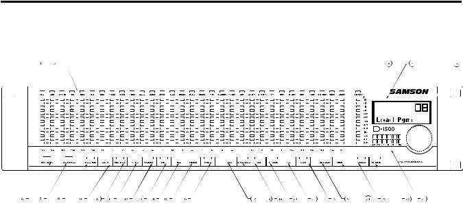
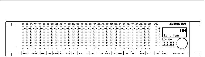
Controls and Functions
Front Panel Layout
1LED METER – 13-segment LED fader for each frequency band,which can be software set for the centers frequency and resolution.
2FREQUENCY LED – Red LED indicating the frequency that is displayed in the LCD display.
3MASTER LED METER -13-segment LED display for displaying the main level.
4LCD DISPLAY – Backlit display that shows the various parameters under control by the operating system.
5DATA WHEEL – Rotary encoder for entering parameter values.
6BYPASS – When the red LED is on,the signal present at the Inputs will be sent directly to the Outputs defeating any DSP processing.
7AUTO EQ – Used to engage the automatic room equalization feature when connected to a D2500 equalizer.
8SOURCE – Assigns the input of the RTA for either the Left, Right,or Left and Right input to the LED Display.
9GAIN – This parameter is used to manage the operating or reference level for the various function modes.
10DETECT – Selects the RTA to operate with either RMS (average) or PEAK detection.
11INTER (INTEGRATION)– Used in conjunction with DETECT to adjust the RTA meter’s response time from 15,65,250,1000,5,000 or 20,000 milliseconds.
12WEIGHT– Used to set an input filter curve with either A,B,C or D weighted filters available.
13REF (REFERENCE) - Selects the display scale of “DIG”,“+4u”,“-10V”,for digital maximum,+4 dBu and
-10 dBV.
14RES (RESOLUTION) -Selects the resolution of the
LED meters,which can be set to operate in a range of 0.5,1.0, 2.0,3.0,or 6dB.
15HOLD- When set to ON the top LED on each band will remain illuminated to assure that maximum level can be recognized,and when AUTO is selected the top LED stays lit then gradually falls.
16FREQ (FREQUENCY) -This parameter is used to set the operating frequency for the various function modes.
17RTA – When pressed,engages the LED lights indicating that the unit is operating as a Real Time Analyzer.
18ANALYZE– When engaged,the LED and the snapshot of the frequency response is held on the LED display.
4
Controls and Functions
19EQ – When selected,the unit is ready to display the equalization curve from any connected
Samson Digital EQ.
20PHASE– When pressed in,the LED switch lights indicating the operating mode is set to Phase meter.
21VU – When engaged,the LED switch lights indicating the operating mode is set to VU meter displaying both PEAK and Average levels.
22GEN (GENERATE) – Press this button and the LED will light indicating the Generator mode is selected,making the Pink Noise and Sine wave generators ready for operation.
23GLOBAL – When engaged,the red LED will illuminate indicating that the unit is in GLOBAL mode, and that the operating system parameters are under control and displayed in the LCD window.
24MIDI switch - This switch is used to page through the MIDI parameters. When selected,the red LED will illuminate and the MIDI parameters will be displayed in the LCD window.
25LOAD switch – Used to load one of the 100 programs from the internal memory.
26STORE switch - Used to store up to 99 programs into the internal memory.
27Main Level Meter - Twelve segment LED meter displays the input level.
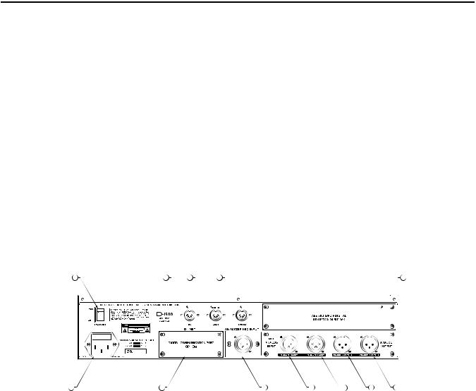
Rear Panel Layout
|
|
|
|
|
|
|
|
|
|
|
|
A POWER SWITCH –When set to the ON position, the |
H ANALYZER MIC INPUT - Balanced XLR microphone |
|||||
D1500 is powered up and ready for operation. |
|
input with phanom power. |
|
|||
B MIDI IN DIN connector –The D1500 receives standard, or |
|
CH1 Balanced XLR jack input - Electronically bal- |
||||
system exclusive, MIDI data here. |
|
|
anced XLR jack input. |
|
|
|
C MIDI OUT DIN connector -The D1500 transmits standard, |
J |
CH2 Balanced XLR jack input - Electronically bal- |
||||
or system exclusive, MIDI data here. |
|
|
anced XLR jack input. |
|
|
|
DMIDI THRU DIN connector -The D1500 passes standard, or system exclusive, MIDI data here.
EI/O Accessory Blank Panel – Removable blanking panel accesses option bay for adding additional Analog-to
Digital or Digital Input/Output boards.
FAC input fuseholder - Connect the supplied heavy gauge 3-pin“IEC”power cable here.
GD-NET Accessory Blank Panel – removable blanking panel accesses option bay for adding the DNET interface card for controlling multiple D class units.
K CH1 Balanced XLR jack output - Electronically balanced XLR jack output.
LCH2 Balanced XLR jack output- Electronically balanced XLR jack output.
5
D1500 Quick Start
Using the D1500 as an RTA.
This section will take you through a quick set-up us-
ing the D1500 as a real time frequency analyzer.
First, remove all packing materials (save them in case of need for future service) and decide where the unit is to be physically placed—it can be used free-stand- ing or mounted in a standard 19”rack.
Before you move ahead, you should become familiar with the various control switch sections. The D1500 front panel switches are set up in groups related to the function or parts of the operating system they control. Some switches are placed individually, since they are dedicated to a single function, and other switches, are arranged in groups since their functionality is related.The D1500 function switch sections are arranged on the front panel as follows:
BY PASS
AUTO EQ
PARAMETERS
NAVAGATION
GLOBAL
MIDI
LOAD and STORE
In this quick start example, we'll take you through the BYPASS and GLOBAL sections, as well as the NAVIGATION and PARAMETER sections. AUTO EQ, MIDI and the LOAD and STORE switches and functions will be covered in detail later on in this manual.
You should know this!
Several of the modes that are controlled by the Navigation switches, have a number of parameters associated that can be adjusted for finer control. Each of these parameters will be explained in detail later on in this manual, however you should know that you can see these parameters by holding the mode switch for 2 seconds. For example, if you press and hold the RTA switch for 2 seconds, you will see all the
LED’s on the parameter switches light.That indicates that all these parameters can be adjusted in the RTA mode. If you press and hold the EQ switch for two seconds, no parameter switches LED’s light, indicating there are no adjustable parameters.
You should know this too !
Many of the D1500 control buttons are capable of accessing more than one parameter, so as you press the switch, you will page through the available parameters. For example, the GLOBAL switch will toggle
between the parameters Input selection and Mic
Gain. You can edit the parameters of any of these functions by using the large DataWheel located by the main LCD display.
GLOBAL
The GLOBAL control allows you to set up the various system parameters including selecting the input/ output and control for the measurement microphone input.
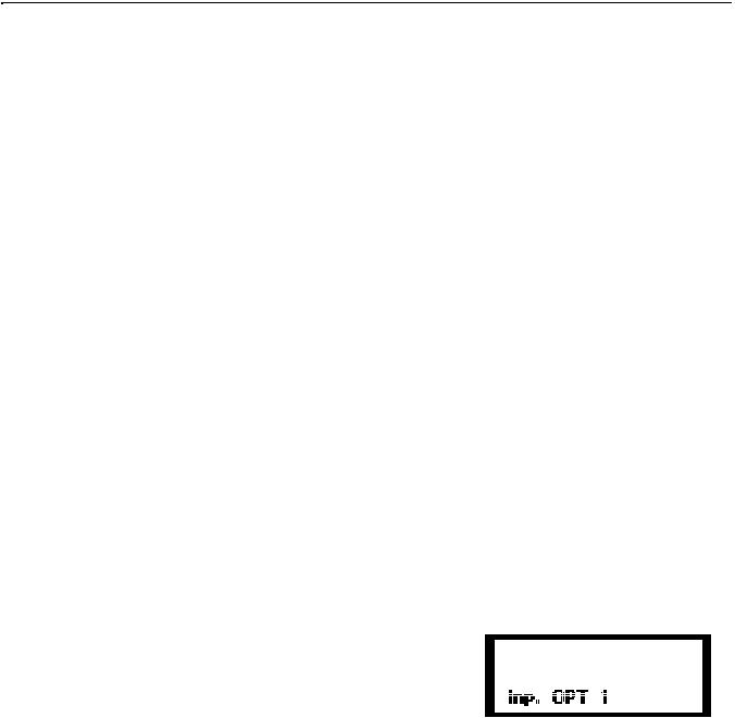
The Global Switch HasTwo Clicks!
Click |
Menu Function |
Value |
|
1 |
Inp. |
Input |
Opt1,Opt2,Mic |
2 |
MG. |
MicGain |
0to+60dB |
Selecting the Input
The D1500 accepts inputs from any of the installed
I/O boards including the optional DIO1 Digital I/O or AIO2, I/O board with premium analog-to-digital and digital-to-analog converters.You can load any combination of these I/O boards in each of the Option 1 or Option 2 card slots.You can also select the input from a connected measurement microphone here. To access the input follow these steps:
•Press the GLOBAL control switch once or twice until you see the: Inp …...
•Use the DataWheel to select OPT 1, OPT 2 or MIC.
NOTE: Once you make an edit to the Global set-up,the red
GLOBAL LED will flash indicating that a change has been made to the original set-up. You will also see that the red STORE LED is illuminated
•To keep the new changes, press STORE again to confirm the change to be saved and you will exit the
GLOBAL mode and both the STORE and GLOBAL the
LED’s will turn off.
6

D1500 Quick Start
Using the Microphone Input
You can use the D1500 as an“in-line device" using the rear panel XLR balanced inputs and outputs, but for many RTA applications, you will want to use a measurement, (test), microphone to analyze the response, phase or level of a sound system. A measurement microphone is a special microphone (usually a condenser microphone), designed to pick-up sound with an extended frequency range, linear or flat response, and a natural sound. A perfect choice for this is the
Samson MM01 Measurement Microphone. For a quick set up for using a measurement microphone with the
D1500 , follow these steps.
Press the RTA switch located in the Navigation section so the amber LED lights.
Plug the measurement microphone into the MIC
INPUT located on the D1500 rear panel.
Note:The D1500 ’s microphone input includes pha tom power, which is always on, for operating condenser microphones.
•To set the D1500 for microphone input, press the
GLOBAL switch until you see the menu: Inp. xxx.
•Now, use the DataWheel to select MIC.You know the input is set to mic when the LCD menu reads:
Inp. MIC. Press STORE.
•Depending on the type of sound system you are measuring you will want to position the microphone approximately 5-10 feet from the speaker system.
•Once the mic is in place, play your program music through your speaker system.
•Next, set the MIC GAIN by pressing the GLOBAL switch until you see the menu: MG. 0 dB.
•While the music is playing, you should see the input level from the measurement microphone reading on theVU meter located under the LCD display. If not, use the DataWheel to adjust the gain from 0dB through +60 dB.
•To keep the new change, press STORE to confirm the change to be saved and you will exit the GLOBAL mode and both the STORE and GLOBAL LED’s will turn off.
•TheVU meter should deflect about half way. If not, repeat the above steps until it does.
7
 Loading...