


S.curve 231
DUAL 31 BAND EQUALIZER
S Class Signal Processors
Safety Instructions
Important Safety Instructions
1. Please read all instructions before operating the unit.
2. Keep these instructions for future reference.
3. Please heed all safety warnings.
4. Follow manufacturers instructions.
5. Do not use this unit near water or moisture.
6. Clean only with a damp cloth.
7. Do not block any of the ventilation openings. Install in accordance with the manufacturers instructions.
8. Do not install near any heat sources such as radiators, heat registers, stoves, or other apparatus (including
amplifiers) that produce heat.
9. Do not defeat the safety purpose of the polarized or grounding-type plug. A polarized plug has two blades with
one wider than the other. A grounding type plug has two blades and a third grounding prong. The wide blade or
third prong is provided for your safety. When the provided plug does not fit your outlet, consult an electrician for
replacement of the obsolete outlet.
10. Protect the power cord from being walked on and pinched particularly at plugs, convenience receptacles and at
the point at which they exit from the unit.
11. Unplug this unit during lightning storms or when unused for long periods of time.
12. Refer all servicing to qualified personnel. Servicing is required when the unit has been damaged in any way,
such as power supply cord or plug damage, or if liquid has been spilled or objects have fallen into the unit, the
unit has been exposed to rain or moisture, does not operate normally, or has been dropped.
Caution: To reduce the hazard of electrical shock, do not
remove cover or back.
No user serviceable parts inside. Please refer all servic-
ing to qualified personnel.
WARNING: To reduce the risk of fire or electric shock, do not expose this unit to rain or moisture.
The lightning flash with an arrowhead symbol within an equilateral triangle, is intended to alert the user to the
presence of uninsulated "dangerous voltage" within the products enclosure that may be of sufficient magnitude
to constitute a risk of electric shock to persons.
The exclamation point within an equilateral triangle is intended to alert the user to the presence of important
operating and maintenance (servicing) instructions in the literature accompanying the product.

Table of Contents
Introduction 2
System Features 3
Controls and Functions
Front Panel 4
Rear Panel 5
Setting Up and Using the S curve 231 6 - 7
System Configurations 8 - 10
About Equalization 11
Grounding Techniques 12
Using a Patchbay 12
Using the S curve 231 with an RTA 13
Using the S curve 231 to Remove Feedback 14
S curve 231 Wiring Guide 15
Specifications 16
Pass-Band Graphs 16
Block Diagram 17
Copyright 2003, Samson Technologies Corp.
Printed Oct., 2003
Samson Technologies Corp.
575 Underhill Blvd.
P.O. Box 9031
Syosset, NY 11791-9031
Phone: 1-800-3-SAMSON (1-800-372-6766)
Fax: 516-364-3888
www.samsontech.com

2
Congratulations on purchasing the Samson S curve 231 dual channel,1/3 Octave, 31 Band Constant Q
Graphic Equalizer! Although this product is designed for easy operation, we suggest you take some
time out first to go through these pages so you can fully understand how we’ve implemented a number
of unique features.
The S curve 231 is a professional quality signal processor that gives you precise tonal control over a
stereo, or two mono audio signals. Center detented sliders with LED illumination allow you to selec-
tively cut or boost selected frequency areas by as much as 24 dB. Front panel controls include output
level sliders, a variable Lowcut filter, as well as Cut Only, Range and Bypass switches. The rear panel
provides electronically balanced inputs and outputs on 1/4-inch and XLR connectors. Thanks to low
noise circuitry, the S curve 231 can be used in a wide variety of applications, including live performance
(in conjunction with either Front Of House or monitor mixers), in broadcast environments, or for record-
ing.
In this manual, you’ll find a more detailed description of the features of the S curve 231, as well as a
guided tour through the front and rear panels, step-by-step instructions for using the unit, suggested
applications for use with a patch bay, a Real Time Analyzer (RTA) or for ringing out monitor systems.
You’ll also find a warranty card enclosed—please don’t forget to fill it out and mail it so that you can
receive online technical support and so we can send you updated information about other Samson
products in the future. Also, be sure to check out our website (http://www.samsontech.com) for com-
plete information about our full product line.
With proper care and adequate air circulation, your S curve 231 will operate trouble free for many
years. We recommend you record your serial number in the space provided below for future reference.
Serial number:
Date of purchase:
Should your unit ever require servicing, a Return Authorization number (RA) must be obtained before
shipping your unit to Samson. Without this number, the unit will not be accepted. Please call Samson at
1-800-3SAMSON (1-800-372-6766) for a Return Authorization number prior to shipping your unit.
Please retain the original packing materials and if possible, return the unit in the original carton and
packing materials.
Introduction
3
S curve 231 Features
The Samson S curve 231 Graphic Equalizer utilizes state-of-the-art, Constant Q filtering technology for
precise tonal control. Here are some of it’s main features:
• The S curve 231 is a two channel equalizer and each channel provides 31 bands of equaliza-
tion, with each frequency band representing 1/3 of an octave in the 20 Hz to 20 kHz range.
• Constant Q circuitry ensures that the bandwidth of the selected frequency area stays the same
even when approaching maximum boost or attenuation. As a result, phase shifting and inter-
modulation distortion is greatly reduced, making for pristine sound.
• The S curve 231 can be set for either 6 or 12 dB of gain and attenuation for each of the fre-
quency bands.
• For monitor applications, the S curve 231 can be set for CUT ONLY mode providing up to 12dB
of attenuation with full slider range.
• Ultra-low noise circuity ensures superb audio fidelity.
•Variable Low Cut Filter for removing rumble and floor noise can be adjusted from 15 to 200 Hz.
• Electronically balanced XLR and TRS inputs and outputs.
• Front panel, hard-wired, relay controlled Bypass switches (with dedicated Bypass LEDs) allow
the equalization circuitry and output level control to be activated or deactivated.
• Main Level control enables output signal to be attenuated or boosted for optimum signal-to
noise ratio.
• LED faders and 8 segment LED bar VU meters.
• Relay power-on circuitry prevents speaker “thumps” when the unit is turned on.
• Internal power supply ensures reliability and trouble-free operation.
• Standard 19", 2 rack-space design for easy integration into any traveling or fixed installation
audio system.
• Optional security cover kit prevents EQ settings from accidentally being altered.
• All-steel chassis makes the S curve 231 eminently road-worthy.
• Three year extended warranty.
4
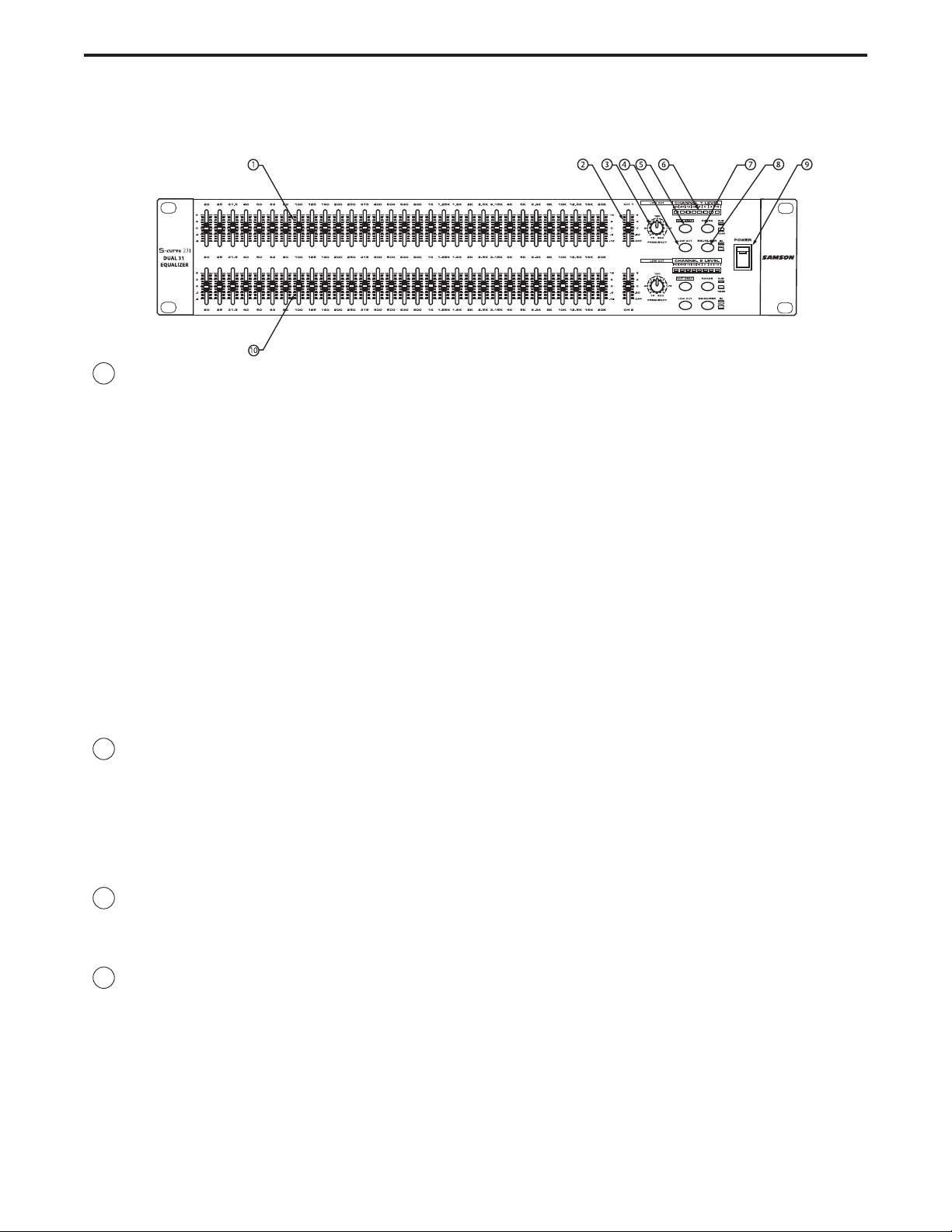
1 Equalizer level sliders - Independent Equalizer sliders are provided for each frequency area (The S
curve 231 provides 31 frequency areas).Calibration markings on either side of each Equalizer slider
allow you to cut or boost each frequency area. As described below, the exact action of the Equalizer
sliders depends upon the setting of the Range switch as well as the setting of the Cut Only switch (see
#3 and #5).
When the Cut Only switch is not pressed in: When an equalizer slider is at its center detented 0 position, the
frequency area is unaffected (that is, there is no boost or cut). When moved all the way up (to the +12
dB) position, the frequency area is boosted by 12 dB (if the corresponding Range switch is notpressed
in) or 6 dB (if the corresponding Range switch is pressed in). When moved all the way down (to the -12
dB position), the frequency area is attenuated by 12 dB (if the corresponding Range switch is not
pressed in) or 6 dB (if the corresponding Range switch is pressed in).
When the Cut Only switch is pressed in: When an equalizer slider is at its top-most position, the frequency
area is unaffected (that is, there is no boost or cut). As the Equalizer slider is moved down, the frequen-
cy area is attenuated. When moved all the way down, the frequency area is attenuated by 6 dB (if the
corresponding Range switch is pressed in) or 12 dB (if the corresponding Range switch is not pressed
in).
2 Main Output level slider - Use this to adjust the output level of signal leaving the S curve 231 via its
rear-panel output connectors (see D on page 5 for more information). When the main slider is at its
center detented 0 position, the corresponding output signal is at unity gain (that is, there is no level cut
or boost). When the main slider is moved all the way up (to the +6 dB) position, the output signal is
boosted by 6 dB. When a Level slider is moved all the way down (to the ∞ position), the output signal is
infinitely attenuated (that is, there is no signal). Note that the Main level slider is deactivated when the
S curve 231 is in Bypass mode (see #7).
3 Frequency control - When the Low Cut switch is pressed in, the variable low cut control is active. You
can adjust the point at which the low frequencies begin to roll off with a frequency range of from 15 to
200 Hz.
4 Low Cut switch - When pressed in, the LED in the switch lights yellow and the variable highpass filter is
applied to the signal. Using the Low Cut can be highly effective in removing rumble and other low fre-
quencies.
Controls and Functions
FRONT PANEL LAYOUT
 Loading...