


 Loading...
TM300
P O W E R E D
M I X E R
OWNERS MANUAL
 ®
®
Table of Contents
ENGLISH
Introduction 3
TM300 Features 3
Guided Tour 5
Overview 5
Channels 6
Main Section 8
Rear Panel 11
Connecting the TM300 12
TM300 Interconnections - Stereo Configuration 13
TM300 Interconnections - Split Mono Configuration 14
Setting Up and Using the TM300 15
Setting the Correct Gain Structure 16
Grounding Techniques 18
Using Equalization 19
Using Pan 21
Using Aux Sends and Returns 22
Using Inserts 23
Using the Internal Effects Processor (DSP) 24
Specifications 58
FRANÇAIS
Introduction 25
Caracté ristiques Techniques du TM300 25
Visite guidé e 27
Les voies 27
Section principale 29
Face arriè re 32
Installation et utilisation du TM300 33
Ré glages de gain 34
Spé cifications 58
DEUTSCHE
Einleitung 36
TM300 Merkmale 36
Ü bersicht 38
die Kanä le 38 Hauptabschnitt 40 Rü ckseite 43
Einstellung und Bedienung des TM300 44
Einstellung der Gain-Struktur 45
Technische Daten 58
ESPAÑ OL
Introducció n 47
Características de la TM300 47
Recorrido guiado 49
Canales 49
Secció n principal 51
Panel trasero 54
Ajuste y uso de la TM300 55
Ajuste de la estructura de ganancia correcta 56
Especificaciones 58
Produced by On The Right Wavelength for Samson Technologies Corp.
Copyright 1999, Samson Technologies Corp.
Printed April 1999
Samson Technologies Corp.
575 Underhill Blvd.
P.O. Box 9031
Syosset, NY 11791-9031
Phone: 1-800-3-SAMSON (1-800-372-6766)
Fax: 516-364-3888

Introduction / TM300 Features
We know you don’t like reading owners manuals, but you’ve just purchased one of the finest powered mixers around, and we want to tell you about it! So, before you plug in and start making music, we’d like to suggest you take just a few moments out to scan these pages. We’ll make it as painless as possible, we promise—and, who knows, you might just pick up a tip or two.
The Samson TM300 is a practical, full-featured 6-channel stereo powered mixer— complete with built-in signal processing—all in a compact tabletop design. It’s ideal for use in rehearsal studios, small club venues, lounges and other sound reinforcement applications—in fact, it can be used wherever there are a number of microphone or line-level sources that need to be mixed down to a stereo output. Simply hook it up to a set of PA speakers and you’re ready to go!
In these pages, you’ll find an overview of TM300 features, followed by a guided tour of its front and rear panels. Then we’ll describe how the TM300 should be connected to your existing equipment (including a wiring diagram) and talk about the important topics of gain structure and grounding techniques. Next, we’ll cover a number of specific TM300 features (such as panning, equalization, auxiliary sends and returns, inserts and using the onboard effects) in detail. Finally, we’ll wrap things up with full specifications. You’ll also find a warranty card enclosed—please don’t forget to fill it out and mail it so that you can receive online technical support and so we can send you updated information about other Samson products in the future. Also, be sure to check out our website (http://www.samsontech.com) for complete information about our full product line.
SPECIAL NOTE: Should your TM300 ever require servicing, a Return Authorization number (RA) is necessary. Without this number, the unit will not be accepted. Please call Samson at 1-800-372-6766 for a Return Authorization number prior to shipping your unit. Please retain the original packing materials and, if possible, return the TM300 in its original carton and packing materials.
TM300 Features
The compact design of the TM300 belies its extraordinary versatility and excellent sound quality. Here are some of its main features:
•Six independent channels, each with mic and line inputs. These allow you to blend together a variety of source signals, including dynamic or condenser microphones, keyboards, CD/tape players, etc. Standard XLR mic connectors (for microphone inputs) and electronically balanced 1/4" jacks (for line-level inputs) are provided for each channel. In addition, there is a dedicated stereo Tape input that provides dual phono (RCA) jacks.
•Flexible switching allows the TM300 to be used either in standard stereo configuration or in a unique “split mono” mode, where it can drive both main PA speakers and onstage monitors simultaneously.
•Built-in stereo power amplifier delivers 150 watts per side into 4 ohms. Any standard speaker cabinets (four, eight, or sixteen ohms) can be connected to the four rear-panel 1/4" speaker output jacks.
•Power amp utilizes a variable-speed fan and bipolar design for maximum reliability and long life.
•Onboard digital signal processor (DSP) with three high-quality effects.
ENGLISH
3

TM300 Features
ENGLISH
•Phantom power switch enables you to use the TM300 with high-quality condenser microphones. When turned on, 48 volts of phantom power is provided to the mic connectors of all channels.
•Two Aux sends per channel (one pre-fader and the other post-fader) allow you to route multiple signals to the internal DSP or to external signal processors.
•Dual stereo aux returns— with dedicated front-panel level controls— give you the ability to blend in the return signal from the internal DSP and/or external signal processors or other line-level devices without having to utilize input channels.
•Extensive equalization includes independent 3-band eq for each channel, with 15 dB of cut or boost for low (100 Hz) and high (10 kHz) frequencies, and 12 dB of cut or boost for the mid (1.8 kHz) frequency. In addition, a dual seven-band graphic master equalizer allows you to “tune” the output of the TM300 to the particular room environment you are in— particularly useful for eliminating ringing or feedback problems. This graphic equalizer can be used in stereo or can be “split” so that one side affects the main PA and the other side affects stage monitors.
•Constant level Pan controls for each channel that allow you to precisely place each input signal in the left-right plane.
•Center detents for all Pan and EQ controls, making it easy to use the TM300 even in low-light live performance situations.
•Continuously adjustable wide-range input Trim controls for each channel allow you to precisely set the correct input and output gain structure.
•Independent 65 mm faders for each channel and for the stereo bus.
•Pre Fader Listen (PFL) soloing for each channel, allowing headphone monitoring of individual channels, pre-fader (but post-EQ) without affecting the signal being output either by the speaker or various line-level outputs.
•Front panel metering system includes a ten-segment level meter and allows you to view at a glance the continuous levels of the main stereo output and/or Aux sends.
•Peak LEDs for each channel show you at a glance when an input signal is on the verge of overloading.
•Dedicated status LEDs show main power and phantom power on/off.
•Separate Record out jacks (with dedicated level control) allow you to directly connect the TM300 to any tape recorder. In addition, a handy Mono output jack provides a line-level signal for connection to external monitor power amplifiers.
•An independent front-panel headphone output with dedicated volume control for private monitoring of the main stereo output, Aux sends, or soloed channels.
•Main inserts and four channel inserts allow you to use outboard signal processors such as equalizers, compressor/ limiters, or noise gates in a standard “effect loop.”
•Last but certainly not least, affordability. The TM300 has been designed from the ground up to provide versatility and excellent sound quality at a cost-conscious price.
4

Guided Tour - Overview
The following illustration shows an overview of the front panel of the TM300:
1
MIC
LINE
INSERT
PEAK 
|
0 |
|
E |
MI |
|
IN |
||
C |
+14–6TRIM–50–30
 0
0
–15 +15
HIGH
 0
0
–12 +12
MID
 0
0
–15 +15
LOW
0 |
+10 |
AUX 1 PRE
0 |
+10 |
AUX 2
2
MIC
LINE
INSERT
PEAK 
|
0 |
|
E |
MI |
|
IN |
||
C |
||
L |
|
+14–6TRIM–50–30
 0
0
–15 +15
HIGH
 0
0
–12 +12
MID
 0
0
–15 +15
LOW
0 |
+10 |
AUX 1 PRE
0 |
+10 |
AUX 2
3
MIC
LINE
INSERT
PEAK 
|
0 |
|
E |
MI |
|
IN |
||
C |
+14–6TRIM–50–30
 0
0
–15 +15
HIGH
 0
0
–12 +12
MID
 0
0
–15 +15
LOW
0 |
+10 |
AUX 1 PRE
0 |
+10 |
AUX 2
4
MIC
LINE
INSERT
PEAK 
|
0 |
|
E |
MI |
|
IN |
||
C |
+14–6TRIM–50–30
 0
0
–15 +15
HIGH
 0
0
–12 +12
MID
 0
0
–15 +15
LOW
0 |
+10 |
AUX 1 PRE
0 |
+10 |
AUX 2
5
MIC
LINE
PEAK 
|
0 |
|
E |
MI |
|
IN |
||
C |
||
L |
|
+14–6TRIM–50–30
 0
0
–15 +15
HIGH
 0
0
–12 +12
MID
 0
0
–15 +15
LOW
0 |
+10 |
AUX 1 PRE
0 |
+10 |
AUX 2
6
MIC
LINE
PEAK 
|
0 |
|
E |
MI |
|
IN |
||
C |
+14–6TRIM–50–30
 0
0
–15 +15
HIGH
 0
0
–12 +12
MID
 0
0
–15 +15
LOW
0 |
+10 |
AUX 1 PRE
+10 |
AUX 2
|
TAPE IN |
REC OUT |
MONO OUT+4dB |
|
–10dB |
+4dBu |
|
L |
R |
L |
R |
|
AUX RET1 |
INSERT |
AUX SEND 1 |
|
|
+4dB
+4dB
L/MONO |
R |
L |
MAIN |
R |
AUX RET 2 |
|
|
POST EQ |
AUX SEND 2 |
SAMSON


0 |
+10 |
TAPE IN
0 |
+10 |
AUX RET 1
0 |
+10 |
AUX SEND 1
0 |
+10 |
REV TO AUX 1
|
LEFT |
RIGHT |
|
|
AUX1 |
AUX2 |
POWER |
|
|
|
|
+4 |
+4 |
+4 |
|
REC OUT |
|
|
|
|
+2 |
+2 |
|
0 |
0 |
0 |
|
|
–2 |
–2 |
PHANTOM |
+10 |
|
||
|
|
|
|
AUX RET2/REV |
–4 |
–4 |
OFF |
|
ON |
||
|
|
|
|
0 |
–9 |
–9 |
|
|
|
|
|
|
–12 |
–12 |
METER HEADPHONE |
+10 |
|
|
|
–15 |
–15 |
SOURCE |
|
AUX SEND 2 |
L / R |
||
DSP |
–20 |
–20 |
AUX 1 / 2 |
|
|||
|
|
|
–25 –25 

VOCAL
|
6 CHANNEL 150 WATT STEREO MIXER |
|
L HALL |
AUX 1/MONITOR |
EQ ON/OFF |
|
|
|
|
LEFT |
RIGHT |
S HALL |
63Hz 160Hz 400Hz 1KHz 2.5KHz 6.4KHz 15KHz |
|
|
|
|
|
|
|
|
|
|
|
|
|
ON |
L |
R |
L |
R |
L |
R |
L |
R |
L |
R |
L |
R |
|
|
PAN |
|
PAN |
|
PAN |
|
PAN |
|
PAN |
|
PAN |
|
|
PFL |
|
PFL |
|
PFL |
|
PFL |
|
PFL |
|
PFL |
|
0 |
|
0 |
|
0 |
|
0 |
0 |
|
0 |
|
10 |
10 |
10 |
|
10 |
|
10 |
|
10 |
10 |
|
10 |
|
0 |
0 |
15 |
|
15 |
|
15 |
|
15 |
15 |
|
15 |
|
4 |
4 |
20 |
|
20 |
|
20 |
|
20 |
20 |
|
20 |
|
8 |
8 |
25 |
|
25 |
|
25 |
|
25 |
25 |
|
25 |
|
12 |
12 |
30 |
|
30 |
|
30 |
|
30 |
30 |
|
30 |
|
16 |
16 |
35 |
|
35 |
|
35 |
|
35 |
35 |
|
35 |
|
20 |
20 |
40 |
|
40 |
|
40 |
|
40 |
40 |
|
40 |
|
26 |
26 |
O |
|
O |
|
O |
|
O |
O |
|
O |
|
OO |
OO |
+12dB
L |
0dB |
-12dB
63Hz 160Hz 400Hz 1KHz 2.5KHz 6.4KHz 15KHz
+12dB
R 


 0dB
0dB
-12dB
63Hz 160Hz 400Hz 1KHz 2.5KHz 6.4KHz 15KHz
0 |
+10 |
LEVEL |
HEADPHONE
1 |
2 |
3 |
4 |
5 |
6 |
L –STEREO– R |
ENGLISH
Channels |
Main Section |
5
Guided Tour - Channels
ENGLISH
|
|
1 |
|
|
|
|
|
|
1 |
MIC |
|
|
|
|
|
|
|
|
2 |
LINE |
|
|
|
|
|
|
|
|
3 |
INSERT |
|
|
||
|
|
PEAK |
4 |
|
|
|
0 |
MI |
|
|
|
E |
|
|
L |
I |
N |
5 |
|
|
C |
|||
|
|
|
||
|
|
|
|
|
|
|
–6 –50 |
|
|
+14TRIM–30 |
|
|||
|
|
0 |
|
|
–15 +15
HIGH
 0
0
6
–12 +12
MID
 0
0
–15 +15
LOW
0 |
+10 |
AUX 1 PRE
7
0 |
+10 |
AUX 2
|
|
8 |
L |
PAN |
R |
|
9 |
|
|
PFL |
|
0 |
|
|
10 |
|
|
15 |
|
|
20 |
|
10 |
|
|
25
30
35
40
O
1
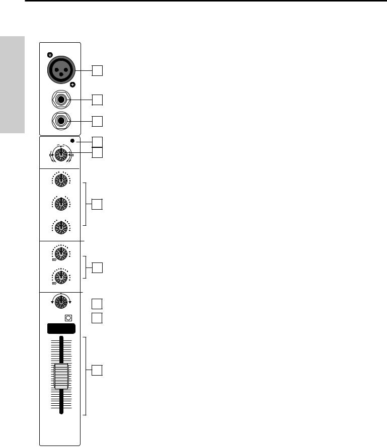
1:Mic inputs - Use these electronically balanced XLR jacks to connect microphones to the TM300. These are intended to accept signal from low-level, low-impedance mics but can also be used for signal from other sources (such as direct injection boxes) if the channel’s Trim control (see #5 below) is turned down. WARNING: Do not connect a channel’s microphone input if you already have something connected to its line input (see #2 below); all channels are designed to accept only one source or the other.
2:Line inputs - Use these electronically balanced 1/4" jacks to connect line-level sources such as synthesizers, drum machines, CD players, tape decks, or effects processors to any of the TM300’s channels. We recommend the use of balanced three-conductor cabling and Tip/Ring/Sleeve (TRS) plugs wherever possible (unbalanced two-conductor plugs can also be inserted into these inputs, but you’ll get better signal quality and less outside noise and hum if you use balanced lines). The “Connecting the TM300” section on page 10 in this manual provides more information on how best to use channel inputs. WARNING: Do not connect a channel’s line input if you already have something connected to its microphone input (see #1 above); all channels are designed to accept only one source or the other.
3:Channel Inserts - Provided in channels 1 - 4 only. Use these to insert an external effects processor (such as outboard equalizer, compressor/limiter or noise gate) in an “effects loop” configuration. These jacks accept 1/4" TRS plugs, with the ring carrying the send signal and the tip carrying the return signal. Normally, this will be connected to a Y-cord; see the “Connecting The TM300” section on page 10 in this manual for more information and a wiring diagram.
4:Peak LED - This warning light indicates an overload situation. It lights whenever a channel’s signal is 3 dB short of clipping. To stop it from lighting (and to eliminate the accompanying sonic distortion), turn down the channel’s input Trim (see #5 below) or reduce the amount of equalization boost (see #6 below).
5:Trim - Determines the input level of the connected signal. This knob is continuously adjustable from +14 dB to -30 dB (in the case of line-level inputs) or from -6 to -50 dB (in the case of mic-level inputs). The input signal is boosted when the Trim control is turned clockwise and is lowered (attenuated) when turned counterclockwise. For information on how to properly set this for each channel, see the section on page 14 entitled “Setting The Correct Gain Structure.”
6:Equalizer - These knobs determine the amount of boost or attenuation in each frequency band (up to 15 dB for low and high frequencies, and up to 12 dB for the mid frequency). The mid frequency control (centered at 1.8 kHz) utilizes a resonant (“bell”) peaking curve, while the high and low frequency controls (centered at 10 kHz and 100 Hz, respectively) utilize shelving curves. A center detent in each knob (at the “0” position) indicates no boost or attenuation (that is, flat response). As each knob is turned clockwise from the “0” position, the frequency area is boosted; as it is turned counterclockwise from the “0” position, the frequency area is attenuated. For more information on the application of EQ, see the “Using Equalization” section on page 17 in this manual.
7:Auxiliary sends - These knobs allow you to route signal to either or both of the TM300’s two monophonic Auxiliary outputs. These are typically used to create submixes (for example, a headphone cue mix) and to feed signal from single or multiple channels to the internal DSP or outboard effects devices. At the “0” (2 o’clock) position, the signal is routed with unity gain (that is, no boost or attenuation). As each knob is turned clockwise from the “0” position, the signal is boosted; as it is turned counterclockwise from the “0” position, it is attenuated. Aux send 1 is pre-eq and pre-fader; that is, the level of the signal is determined solely by its Trim control (see #5 on the previous page). In contrast, Aux
6

Guided Tour - Channels
send 2 is post-eq and post-fader; that is, the level of the signal is determined by the channel’s Trim control, its EQ settings, and the position of its fader. Aux send 2 is used for routing signal to the TM300’s internal DSP For more information, see the “Using Aux Sends and Returns” and “Using the DSP” sections on pages 20 and 22 in this manual.
8:Pan - This knob allows you to place the input signal anywhere in the left-right stereo spectrum, while keeping the overall signal level constant. When the knob is placed at its center (detented) position, the signal is sent equally to both the left and right speaker outputs. When moved left of center, less signal is sent to the right output and more signal is sent to the left output (making the sound appear left of center) and when moved right of center, less signal is sent to the left output and more signal is sent to the right output (making the sound appear right of center). To route a signal hard left or right, place the pan knob either fully counterclockwise or fully clockwise. For more information, see the “Using Pan” section on page 19 in this manual.
9:PFL (“Pre Fader Listen”) switch - When pressed in, the channel is soloed in connected headphones (see #24 on page 8). Soloing is non-destructive; that is, it has no effect on the main stereo output.
10:Channel Fader - This linear slider determines the signal level being sent to the main output as well as affecting the signal level being routed to Aux send 2 (which is post-fader; Aux 1 is always pre-fader). In practice, you will use the channel faders to continuously adjust the levels of the various signals being blended together by the TM300. The “0” position of the fader indicates unity
gain (no level attenuation or boost). Moving the fader down from the “0” position (towards “∞ ”) causes the signal to be attenuated (at the very bottom, it is attenuated infinitely— in other words, there is no sound).
For best signal-to-noise ratio, all faders for channels carrying signal should generally be kept at or near their “0” position. Channels that are unused should have their faders kept all the way down at their “∞ ” (minimum) level. See the “Setting the Correct Gain Structure” section on page 14 in this manual for more information.
ENGLISH
7
Guided Tour - Main Section
ENGLISH
3
|
TAPE IN |
|
REC OUT |
|
|
MONO OUT+4dB |
|
–10dB |
|
+4dB |
|
|
5 |
L |
R |
|
L |
R |
|
|
1 |
|
|
|
|
|
AUX SEND 1 |
|
AUX RET1 |
|
INSERT |
|
|
|
|
|
|
|
|
||
|
+4dB |
|
|
|
|
|
2 |
|
|
|
|
|
+4dB |
R |
L |
MAIN |
|
R |
6 |
|
L/MONO |
|
|
|
|
||
|
AUX RET 2 |
|
POST EQ |
|
|
AUX SEND 2 |
4
SAMSON 


11
7 |
0 |
|
LEFT |
|
RIGHT |
|
|
|
|
AUX1 |
|
AUX2 |
12 |
8 |
|
|
|
|
POWER |
|
+10 |
+4 |
+4 |
+4 |
|
||
TAPE IN |
REC OUT |
+2 |
+2 |
|
||
9 |
|
|
|
13 |
||
0 |
0 |
-2 |
-2 |
PHANTOM |
||
|
0 |
0 |
|
|
||
|
+10 |
+10 |
|
|
|
14 |
10 |
AUX RET 1 |
AUX RET2/REV |
-9 |
-9 |
OFF |
|
0 |
0 |
|
||||
|
|
|
-4 |
-4 |
ON |
|
|
|
|
|
|
|
|
|
|
|
-12 |
-12 |
METER HEADPHONE |
|
|
+10 |
+10 |
|
|
|
|
|
|
|
SOURCE |
|
AUX SEND 1 |
AUX SEND 2 |
-15 |
-15 |
L/R |
15 |
|
|
-20 |
-20 |
AUX 1/2 |
|
|
DSP |
|
16 |
0 |
-25 |
-25 |
|
|
VOCAL |
|
|
|
|
|
+10 |
6 CHANNEL 150 WATT STEREO MIXER |
19 |
|||
|
REV TO AUX 1 |
|
|
|
|
17 |
L HALL |
AUX 1/MONITOR |
EQ ON/OFF |
||
|
|
|
LEFT |
RIGHT |
|
S HALL |
63Hz 160Hz 400Hz 1KHz 2.5KHz 6.4KHz 15KHz |
20 |
|
18 |
|
|
|
|
|
|
+12dB |
|
|
ON |
|
|
|
|
|
|
|
|
L |
|
|
|
0dB |
|
|
|
|
|
|
|
-12dB |
|
|
|
63Hz |
160Hz 400Hz |
1KHz |
2.5KHz 6.4KHz 15KHz |
21 |
|
|
|
|
|
|
|
+12dB |
|
10 |
10 |
|
|
|
|
|
|
|
|
R |
|
|
|
0dB |
|
0 |
0 |
|
|
|
|
-12dB |
|
4 |
4 |
63Hz |
160Hz 400Hz |
1KHz |
2.5KHz 6.4KHz 15KHz |
|
22 |
8 |
8 |
|
|
|
0 |
23 |
|
12 |
12 |
|
|
|
+10 |
|
|
|
|
|
|
|
|
|
|
16 |
16 |
|
|
LEVEL |
|
|
|
|
|
|
|
|
||
20 |
20 |
26 |
26 |
OO OO
24
HEADPHONE
L –STEREO– R
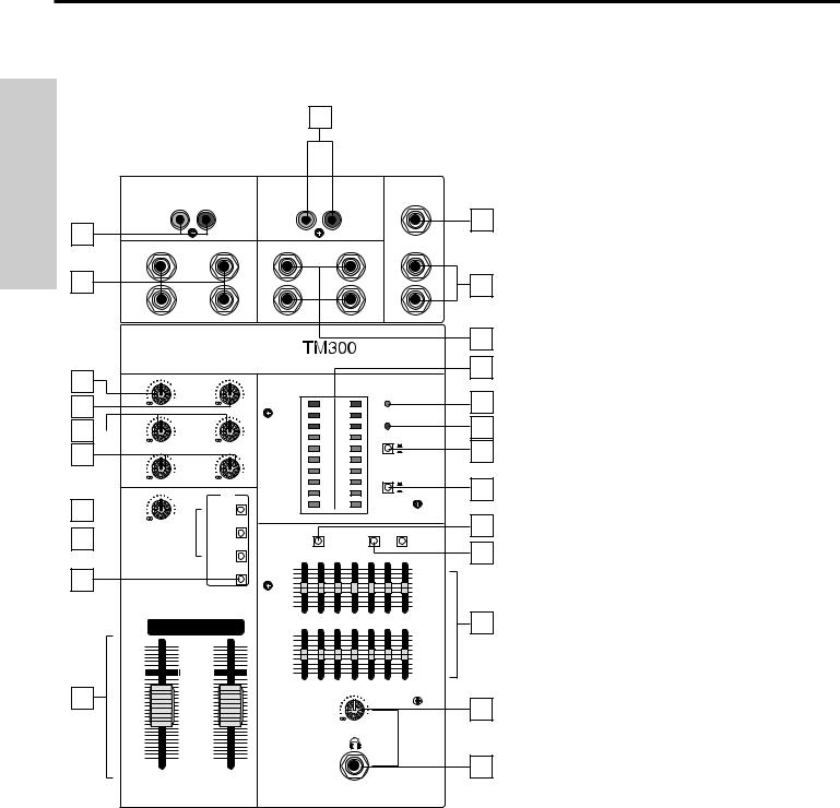
1:Tape input (L, R) - Connect the outputs of a tape or CD player to this set of dual phono jacks. The volume of the incoming signal is controlled by the Tape In level control (see #7 on the next page).
2:Aux Returns (1, 2) - Connect signal from external stereo devices such as effects processors to these unbalanced 1/4" jacks. See the “Connecting the TM300” section on page 10 and the “Using Aux Sends and Returns” section on page 20 in this manual for more information.
3:Record outputs (L, R) - This set of dual phono jacks allow you to connect the output of the TM300 to the inputs of a two-track recorder. The volume of the incoming signal is controlled by the Record Out level control (see #8 on the next page). See the “Connecting the TM300” section on page 10 in this manual for more information.
4:Main Inserts (L, R) - Use these to insert an external effects processor (such as outboard equalizer, compressor/limiter or noise gate) across the TM300’s main stereo output in an “effects loop” configuration. This enables you to process the entire mix simultaneously at unity gain. The “Post EQ” pair of Main Inserts is affected by both the seven-band graphic master equalizer and stereo faders, while the “Pre EQ” pair is not. These jacks accept 1/4" TRS plugs, with the ring carrying the send signal and the tip carrying the return signal. Normally, this will be connected to a Y-cord; see the “Connecting The TM300” section on page 10 in this manual for more information and a wiring diagram. The Main Inserts can also be used to link multiple TM300s or to bring the output from another mixer into the TM300 without taking up channel line inputs.
See the “Using Inserts” section on page 21 in this manual for more information.
5: Mono Out - This unbalanced 1/4" jack provides a monophonic line-level output, unaffected by the Stereo faders (see #22 on page 8). It can be used to connect the TM300 to an external monitor mixer/amplifier/speaker system so that performers can receive an onstage monitor mix. See the “Connecting the TM300” section on page 10 in this manual for more information.
6: Aux Sends (1, 2) - These unbalanced 1/4" jacks allow you to route signal from either of the TM300’s two discrete Aux Sends to external devices such as effects processors. Aux send1 is pre-fader, while Aux Send 2 is post-fader. See the “Using Aux Sends and Returns” section on page 20 in this manual for more information.
8

Guided Tour - Main Section
7: Tape In Level - Controls the level of signal arriving at the Tape Input jacks (see #1 on the preceding page). |
|
|
8: Record Out Level - Controls the level of signal being output by the Record Out jacks (see #3 on the preceding page). |
ENGLISH |
|
9: Auxiliary Return Level (1,2) - These knobs determine the input level of signal arriving via the TM300’s two stereo |
||
|
||
Auxiliary return jacks (see #2 on the previous page). The “0” (2 o’clock) position of each knob indicates unity gain |
|
|
(no level attenuation or boost). Moving each knob counterclockwise from the “0” position (towards “∞ ”) causes the signal |
|
|
to be attenuated (at the fully counterclockwise position, it is attenuated infinitely— in other words, there is no sound). |
|
|
Moving each knob clockwise from the “0” position (towards “+10”) causes the signal to be boosted by as much as 10 dB. |
|
|
Note that, when the DSP On/Off switch (see #19 on the next page) is pressed in, the internal DSP signal is instead |
|
|
routed to Aux Return 2, with the Aux Return Level 2 knob controlling the amount of “wet,” processed signal. For |
|
|
information on how to properly set these, see the sections in this manual entitled “Setting the Correct Gain Structure,” |
|
|
“Using the Aux Sends and Returns” and “Using DSP” (pages 14, 20 and 22). |
|
|
10: Auxiliary Send Level (1,2) - These knobs determine the output level of signal being routed to the TM300’s two |
|
|
stereo Auxiliary Send jacks (see #6 on the preceding page) and, in the case of Aux Send 2, to the internal DSP (see the |
|
|
“Using DSP” section on page 22 in this manual). The “0” (2 o’clock) position of each knob indicates unity gain (no level |
|
|
attenuation or boost). Moving each knob counterclockwise from the “0” position (towards “∞ ”) causes the send signal to |
|
|
be attenuated (at the fully counterclockwise position, it is attenuated infinitely— in other words, there is no signal being |
|
|
sent). Moving each knob clockwise from the “0” position (towards “+10”) causes the send signal to be boosted by as |
|
|
much as 10 dB. For information on how to properly set these, see the sections in this manual entitled “Setting the |
|
|
Correct Gain Structure” and “Using the Aux Sends and Returns” (pages 14 and 20). |
|
|
11: Meter - This ten-segment bar meter shows either the Left/Right output level or the Aux 1/2 Send level, depending |
|
|
upon the setting of the Meter Headphone Source switch (see #15 below). For optimum signal-to-noise ratio, try to adjust |
|
|
all left/right and Aux send levels so that program material is usually at or around 0 dB, with occasional but not steady |
|
|
excursions to the red “+” segments. For more information, see the sections in this manual entitled “Setting the Correct |
|
|
Gain Structure” and “Using the Aux Sends and Returns” (pages 14 and 20). |
|
|
12: Power LED - Lights steadily green whenever the TM300 is powered on. |
|
|
13: Phantom LED - Lights steadily red when the Phantom Power switch (see #14 below) is engaged. |
|
|
14: Phantom Power switch - When this switch is pressed in, the TM300 delivers 48 volts of phantom power to pins |
|
|
2 and 3 of all XLR microphone connectors in all channels. WARNING: Only use this switch with the TM300 powered |
|
|
down. Before turning phantom power on, be sure to disconnect all non-microphone signal sources (such as passive |
|
|
direct injection boxes) from the XLR mic jacks. Although phantom power will have no adverse affect on connected |
|
|
dynamic microphones, it should be used only when one or more condenser microphones are connected to the TM300. |
|
|
Refer to the owners manual of your microphone to determine whether or not it requires 48 volts phantom |
|
|
power—we cannot assume responsibility if you damage a mic by incorrectly applying phantom power. If you’re |
|
|
not completely certain that one or more connected mics require 48 volts phantom power, leave this switch off (its out |
|
|
position). |
|
15:Meter / Headphone Source switch - When out (the “up” position), the Left/Right stereo output signal is routed to the headphones jack (see #24 on the next page) and to the ten-segment meter (see #11 on the previous page).
When pressed in, the Aux send 1 and 2 output signals are routed to the headphones jack and to the ten-segment meter. Note that, whenever any channel PFL switches are depressed (see #9 on page 5), the soloed channel(s) are instead routed to the headphones jack (though not to the meter).
16:Rev To Aux 1 Level - This knob determines the level of signal being routed from the internal DSP to Aux Send 1.
It allows you to add reverb or other signal processing to the sound in onstage monitors or headphones connected to the TM300 Aux Send 1 jack (when operating the TM300 in standard stereo configuration) or the right speaker outputs (when operating the TM300 in “split mono” configuration; that is, when the Aux 1 / Monitor switch [see #19 on the next page] is pressed in). For more information, refer to the wiring interconnection diagrams on pages 11 and 12 and to the sections in this manual entitled “Using the Aux Sends and Returns” and “Using DSP” on pages 20 and 22.
9

Guided Tour - Main Section
17: DSP select switches - Allows you to select any of three preset reverb effects for the onboard DSP: Vocal, Long Hall (“L HALL”) or Short Hall (“S HALL”). For more information, see the “Using DSP” section on page 22 of this manual.
ENGLISH |
18: DSP On/Off switch - When pressed in (“On”), output signal from the internal DSP is routed to Aux Return 2. When |
|
|
|
up (“Off”), Aux Return 2 instead receives signal from any device connected to the Aux Return 2 jacks. For more |
|
information, see the “Using the Aux Sends and Returns” and “Using DSP” sections on pages 20 and 22 in this manual. |
|
19: Aux 1 / Monitor switch - When pressed in, Aux send 1 is routed to the right side of the TM300’s power amplifier and |
|
the stereo mix is automatically combined to mono and routed to the left side of the TM300’s power amplifier. This allows |
|
the TM300 to be used in a “split mono” configuration, so that it can drive both main “Front Of House” PA speakers (from |
|
the left speaker output ) and onstage monitors (from the right speaker output) without the need for any external power |
|
amplifier. When used in a “split mono” configuration, the Rev To Aux 1 Level knob allows you to route signal from the |
|
internal DSP to your onstage monitors (the signal can also be routed to Aux Return 2 for simultaneous use in the main PA |
|
signal. For more information, see the “Using the Aux Sends and Returns” and “Using DSP” sections on pages 20 and 22 |
|
in this manual. |
|
20: EQ On/ Off switches (L, R)- When pressed in (“On”), the equivalent side of the master seven-band graphic |
|
equalizer is active; when out (“Off”), the equivalent side of the master seven-band graphic equalizer is inactive regardless |
|
of the settings of the EQ sliders (see #21 below). Note that, when using the TM300 in a “split mono” configuration (that is, |
|
when the Aux 1 / Monitor switch [see #19 above] is pressed in), the left side of the graphic equalizer affects the main |
|
“Front Of House” PA speakers and the right side affects the onstage monitors, saving you the expense of having to use a |
|
separate outboard graphic equalizer for your onstage monitors. |
|
21: Graphic EQ sliders - These sliders allow you to add 12 dB of boost or attenuation to seven different frequency |
|
areas. When a slider is at its center detented (“0 dB”) position, the selected frequency area is unaffected (it is said to be |
|
flat). When a slider is moved up (above the “0 dB” position, towards the “+12 dB” position), the selected frequency area |
|
is boosted, and when it is moved down (below the “0 dB” position, towards the “-12 dB” position), the selected frequency |
|
area is attenuated. For more information, see the “Using Equalization” section on page 17 in this manual. |
|
22: Stereo Faders - These linear sliders determine the relative level of the main left/right stereo outputs. The “0” |
|
position of each fader indicates unity gain (no level boost or attenuation). Moving each fader below this position (towards |
|
the “∞ ” position) causes the signal to be attenuated (at the very bottom, it is attenuated infinitely— in other words, there is |
|
no sound). For best signal-to-noise ratio, both Stereo faders should generally be kept at or near the 0 level. For more |
|
information, see the “Setting The Correct Gain Structure” section on page 14 in this manual. |
|
23: Headphone Level - This knob sets the level of the signal sent to the headphone jack (see #24 below). |
|
WARNING: To avoid possible damage to connected headphones (or, worse yet, to your ears!), always turn this all the |
|
way off (to the fully counterclockwise “0” position) before plugging in a pair of headphones— then raise the level slowly |
|
while listening. The Headphone Level has no effect on any other TM300 outputs. |
|
24: Headphone jack - Connect any standard stereo headphones to this jack (via a 1/4" TRS plug) for private monitoring |
|
of the stereo output, Aux sends, or soloed channels (depending upon the setting of the Meter Headphone Source switch |
|
[see #15 on the preceding page] and whether or not any channel PFL switches have been pressed in). The built-in |
|
TM300 headphone preamp delivers approximately 100 mw of power. |
10
Guided Tour - Rear Panel
POWER
TM300 6 CHANNEL 150WATT STEREO MIXER
SAMSON |
ON |
CAUTION |
SERIAL NUMBER |
OFF |
RISK OF ELECTRIC SHOCK |
|
|
DO NOT OPEN |
|
|
AVIS; |
CAUTION: TO REDUCE THE |
SPEAKER |
RISQUE DE CHOC ELECTRIQUE |
OUT |
|
RISK OF FIRE, REPLACE ONLY |
|
|
NE PAS OUVRIR |
|
|
DO NOT EXPOSE THIS EQUIPMENT |
WITH SAME TYPE FUSE. |
|
TO RAIN OR MOISTURE. |
|
|
|
FUSE |
|
|
8A/250V(115V) |
|
|
4A/250V(230V) |
|
|
AC INPUT |
|
|
115V/230V,50/60Hz |
|
|
780W |
|
|
R |
L |
USE CLASS 2 WIRING MINIMUM LOAD IMPEDANCE 4Ω
CAUTION:
DO NOT BLOCK AIRFLOW
1 |
|
2 |
|
3 |
|
4 |
|
5 |
|
6 |
1:Vent - To ensure proper cooling of the TM300 power amplifier, make sure this vent is unobstructed at all times.
2:Fuse holder - Holds an 8 A / 250 V fuse for 115 volt operation or a 4 A / 250 V fuse for 230 volt operation
3:AC input - Connect the supplied heavy gauge 3-pin “IEC” power cable here.
4:Speaker Outputs - These are the TM300’s main outputs; use these four unbalanced jacks (two of which carry the left signal and two of which carry the right) to connect the TM300 to loudspeakers rated at 4 ohms or greater (that is, 4, 8, or 16 ohms). The lower the ohm rating, the greater the power output. We recommend the use of 4 ohm speakers for long-term usage. The TM300 delivers 150 watts of power per channel into 4 ohms at less than 1% THD (Total Harmonic Distortion). In order to ensure correct
phase correlation, the tip of the TM300 speaker jack should be connected to the “+” (hot) input of your loudspeaker, and the sleeve of the TM300 speaker jack should be connected to the “-” (ground) input of your loudspeaker. Note that, when the Aux 1 / Monitor switch (see # 19 on page 8) is pressed in, the TM300 operates in a “split mono” configuration, where the left speaker output carries the main stereo output (internally mixed to mono) and the right speaker output carries Aux send 1.
5:Power on-off switch - As you may have guessed, this is what you use to turn the TM300 on and off. If the TM300 is connected to external power amps (via its Main Insert and/or Mono output jacks— see #4 and #5 on page 6 in this manual), turn it on before you turn on the connected amps— and turn it off after the connected amps are turned off.
6:Fan - This variable-speed fan provides vital cooling to your TM300 power amp
(the hotter the amp gets, the faster the fan blows!). Make sure that cool, fresh air is accessible at all times. Also, try to ensure that the TM300 is used in a dust-free environment.
ENGLISH
11
Connecting the TM300
ENGLISH
The actual connections you’ll make to and from the TM300 will vary according to the environment you use it in and the particular equipment you have. Here are a few basic rules concerning TM300 connections that will apply in most situations:
•In general, it’s best to make all connections with the TM300 turned off. If you must
make connections with the power on, make sure that all faders are completely down (at their “∞ ” position). If the TM300 is connected to any external power amplifiers, turn them off first. Wait a few seconds for their power supplies to discharge and then turn off all other connected equipment, turning the TM300 off last.
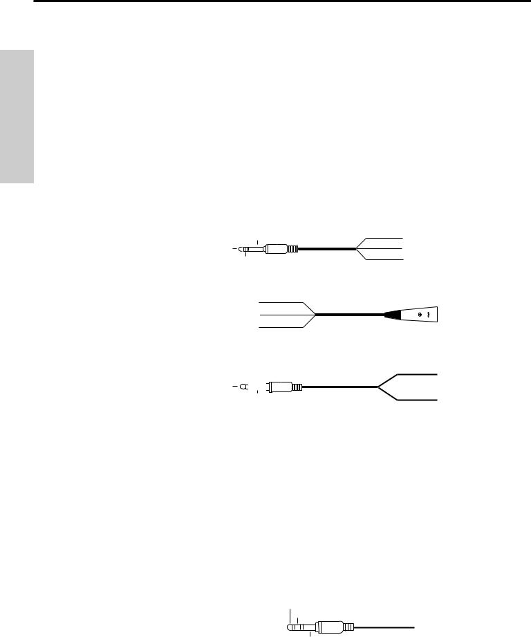
•Try to use balanced connectors and cabling wherever possible. These kind of connections do a better job of rejecting extraneous noise and hum and generally provide a cleaner signal. Although the TM300 will accept unbalanced connectors throughout, it specifically provides electronically balanced inputs for all mono channel line inputs. The wiring diagram below shows how 1/4" TRS (Tip/Ring/Sleeve) connectors should be wired:
SLEEVE |
TIP + |
TIP |
GROUND |
RING |
RING - |
XLR connectors for mono channel mic-level inputs should be wired as follows:
3 - SIGNAL
1 GROUND |
TO MIC |
2 + SIGNAL
Unbalanced cables use standard 1/4" phone connectors, wired as follows:
|
+ SIGNAL |
+ SIGNAL |
|
GROUND |
GROUND |
•Always make one connection at a time and then monitor the incoming signal. If you hear a distinct hum or buzz, you may have a grounding problem with that particular device. See the “Grounding Techniques” section on page 16 in this manual for information on how to avoid grounding problems.
•NEVER connect a microphone and line level input to the same channel simultaneously— use one or the other. You can have some channels connected to microphones and others to line level signals (for example, you might want to plug mics into channels 1 - 4 and line level signals into the remaining channels)— just don’t have both kinds of inputs connected to the same channel.
•There are two “hidden” (or at least not so obvious) stereo inputs to the TM300; these are the Auxiliary returns. Use these whenever you want to bring in stereo signals that will not need to be equalized or otherwise processed.
•Channel and Main insert cables (sometimes called “Y-cords”) should terminate in standard 1/4" TRS jacks (ring to send and tip to return), wired as follows:
TIP (RETURN)
RING (SEND)
SLEEVE (GROUND)
12
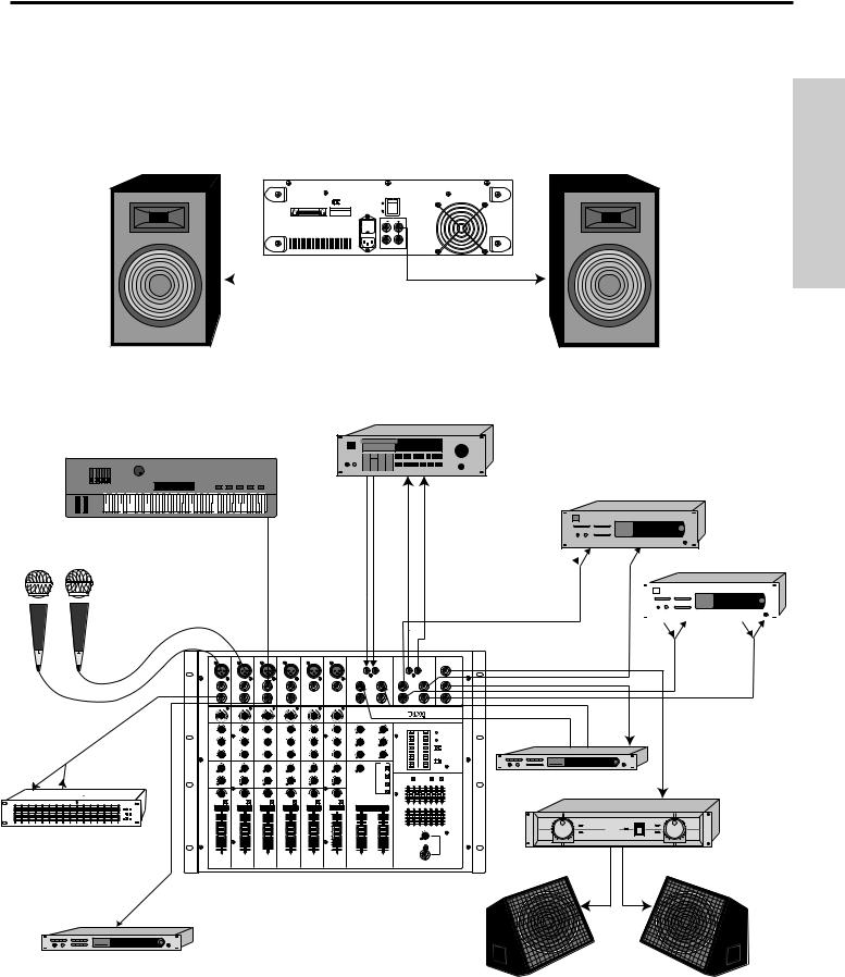
TM300 Interconnections - Stereo Configuration
The illustration below shows typical interconnections between the TM300 and other audio equipment when used in its standard stereo configuration (that is, with the Aux 1 / Monitor switch [see #19 on page 8] out).
TM300 6 CHANNEL 150WATT STEREO MIXER |
POWER |
CAUTION: |
SAMSON |
DO NOT BLOCK AIRFLOW |
CAUTION |
SERIAL NUMBER |
|
|
AVIS; |
CAUTION: TO REDUCE THE |
|
||
|
|
|
RISK OF FIRE, REPLACE ONLY |
|
||
|
|
|
WITH SAME TYPE FUSE. |
|
||
|
|
|
|
|
|
|
|
|
|
|
|
|
|
|
|
|
|
|
|
|
|
|
|
|
|
|
|
ENGLISH
CASSETTE or DAT
MIDI KEYBOARD |
|
|
|
L |
R |
L |
R |
STEREO PARAMETRIC EQ
L Tip Ring Tip
 Ring R
STEREO COMPRESSOR
|
|
|
|
|
|
|
|
|
|
|
|
|
|
|
|
|
|
|
|
|
|
|
|
|
|
|
|
|
|
|
|
|
|
|
|
|
|
|
|
|
|
|
|
|
|
|
|
|
|
|
|
|
|
|
|
|
|
|
|
|
|
|
|
|
|
|
|
L Tip |
Ring |
Tip |
Ring R |
|||
1 |
2 |
3 |
4 |
5 |
6 |
L R L R
MIC |
MIC |
MIC |
MIC |
MIC |
MIC |
SAMSON |
|
|
|
|
|
|
L R
SIGNAL PROCESSOR
Ring Tip
SIGNAL PROCESSOR
SAMSON
SAMSON |
SERVO - 240 |
O O O O O O OO OO
1 2 3 4 5 6 L –STEREO– R
Ring  Tip
Tip
SIGNAL PROCESSOR
13
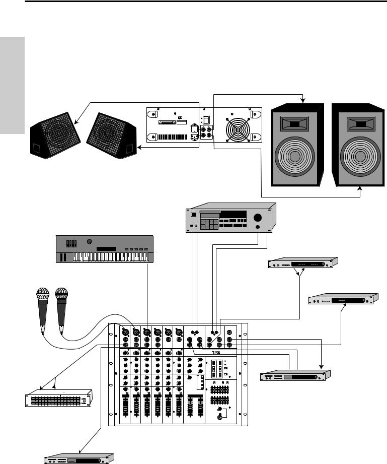
TM300 Interconnections - Split Mono Configuration
ENGLISH
The illustration below shows typical interconnections between the TM300 and other audio equipment when used in its “split mono” configuration (that is, with the Aux 1 / Monitor switch [see #19 on page 8] pressed in). Note that , in this conguration, the Rev To Aux 1 Level control (#16 on page 8) can be used to route internal DSP signal to the onstage wedge monitors (the Aux 2 Return Level can still be used to route DSP signal to the main PA speakers as well).
TM300 6 CHANNEL 150WATT STEREO MIXER |
POWER |
CAUTION: |
SAMSON |
DO NOT BLOCK AIRFLOW |
CAUTION |
SERIAL NUMBER |
|
AVIS; |
CAUTION: TO REDUCE THE |
|
|
|
|
RISK OF FIRE, REPLACE ONLY |
|
|
|
|
WITH SAME TYPE FUSE. |
|
|
|
|
|
|
|
|
|
|
|
|
|
|
|
|
|
CASSETTE or DAT
L R L 
 R
R
MIDI KEYBOARD |
MONO COMPRESSOR
Tip Ring
MONO COMPRESSOR
Tip Ring
Ring
|
1 |
2 |
3 |
4 |
5 |
6 |
|
|
|
|
|
|
|
|
|
|
|
|
L |
R |
L |
R |
|
|
MIC |
MIC |
MIC |
MIC |
MIC |
|
MIC |
SAMSON |
|
|
|
|
|
|
|
|
|
|
|
|
|
||
|
|
|
|
|
|
|
|
|
|
L |
R |
|
|
|
|
|
|
|
|
|
|
SIGNAL PROCESSOR |
|
Ring |
Tip |
|
|
|
|
|
|
|
|
|
|
|
SIGNAL PROCESSOR |
|
|
|
|
|
|
|
|
|
|
|
SAMSON |
|
|
|
|
|
|
|
|
|
|
|
O |
O |
O |
O |
O |
O |
OO |
OO |
|
|
|
|
1 |
2 |
3 |
4 |
5 |
6 |
L |
–STEREO– |
R |
|
|
Ring  Tip
Tip
SIGNAL PROCESSOR
14

Setting Up and Using The TM300
Setting up your TM300 is a simple procedure which takes only a few minutes:
1.Remove all packing materials (save them in case of need for future service) and decide where the TM300 is to be physically placed. Make sure that the rear vent and fan are unobstructed and that there is good ventilation around the entire unit.
2.Before even plugging the TM300 into an AC socket, begin by making its speaker connections. It is never a good idea to power up any amplifier that is not connected to loudspeakers. Any loudspeakers with a minimum impedance load of 4 ohms (that is,
4ohms or greater) can be used, but we recommend the use of 4 ohm speakers for long-term usage. In order to ensure correct phase correlation, be sure that the connection from the tip of the TM300 speaker jack goes to the “+” (hot) input of your loudspeaker, and that the sleeve of the TM300 speaker jack is connected to the “-” (ground) input of your loudspeaker.
2a. If you are planning to use the TM300 in a standard stereo configuration, make sure the Aux 1 / Monitor switch is in its up (“out”) position and make connections between the left speaker output(s) and your left main PA speaker(s) and between the right speaker output(s) and your right main PA speakers. See page 11 for an example diagram.
2b. If you are planning to use the TM300 in a “split mono” configuration, make sure the Aux 1 / Monitor switch is pressed in (“on”) and make connections between the left speaker output(s) and your main PA speaker(s) and between the right speaker output(s) and your onstage monitors. See page 12 for an example diagram.
3.Next, make all required connections to the various TM300 line-level outputs (Record Out, Mono Out, and Aux Sends 1 and 2) and line-level inputs (Tape In, Aux Returns 1 and 2). Do not make any insert connections at this time— these should be made after the gain structure is correctly set (see pages 14 - 15).
4.Make the input connections to the mic or line inputs of the various channels. WARNING: Do not connect a channel’s line input if you already have something connected to its microphone input, or vice versa; each mono channel is designed to accept only one source or the other.
5.Bring all channel faders and the left-right stereo faders completely down (to their “∞ ” setting). Turn all Trim controls fully counterclockwise. Set the front-panel Phantom switch to its “off” (out) position unless you are absolutely certain that all connected microphones require 48 volt phantom power; if so, set the Phantom switch to its “on” (in) position.
6.Plug the TM300 into any grounded AC socket using the supplied heavy gauge IEC cord. Because of the special relay protection circuitry built into the TM300, you can even plug it into the same power strip that other audio devices are connected to. You can then turn on all devices at once with the single power strip on-off switch, with no danger of damaging connected speakers by generating “thumps.”
7.Finally, press the rear panel Power switch in order to turn on the TM300.
The front-panel Power LED will go on.
ENGLISH
15

Setting the Correct Gain Structure
ENGLISH
You’re now ready to establish the correct gain structure— the key to getting the best performance from the TM300, or from any mixer, for that matter. This is a simple procedure that ensures optimum input and output levels so that no unnecessary noise (caused by too low a signal) or overload distortion (caused by too high a signal) is created. Here’s a step-by-step description of how to do so:
a.With all connections made (as described in the previous section) but with the power off, bring all channel faders and the left-right stereo faders completely down (to their “∞ ” setting).
b.Turn all channel Trim controls fully counterclockwise.
c.Place all channel equalizer knobs in their center detent “0” positions and turn off the seven-band graphic master equalizer by setting the EQ On/Off switches to their “Off” (up) position.
d.Set the Meter/Headphone Source switch up (to its “L/R” position); this will ensure that the TM300 meter shows the continuous level of the Left/Right stereo output signal.
e.Turn all channel Aux Send knobs and the main section Aux Return knobs to their fully counterclockwise (“∞ ”) position. Turn the main section Tape In and Rev To Aux 1 knobs to their fully counterclockwise (“∞ ”) position.
f.Set both main section master Aux Send knobs to their “0” (2 o’clock) position.
g.Power up all devices connected to the TM300 channel line inputs and Aux Returns and set their level controls to unity gain or, if there is no unity gain indicated on their output control, to maximum. If you’ve got outboard effects processors connected to the Aux Returns, make sure they are sending completely “wet” (processed) signal, with no “dry” (unprocessed) signal mixed in.
h.If condenser microphones are connected to the TM300, turn on the Phantom switch.* Finally, turn on the TM300’s main power.
i.Play an instrument connected to one of the TM300’s line inputs** and, while doing so, raise the corresponding channel fader to the “0” position. You should see the segment meter begin to move— adjust the input Trim control for that channel so that the “0” segment lights frequently and the “+3” segment lights only occasionally. The Peak LED for that channel should not flash at even the highest level input signals. If the incoming signal seems too hot even with the input channel Trim all the way at its minimum setting, you may need to lower the output level of the instrument, though this will rarely occur. Conversely, if the signal is too low even with the Trim all the way up, something’s definitely wrong: in all likelihood, the connecting audio cable is faulty.
j.Once you’ve set the optimum level in step (i) above, continue playing the instrument and slowly raise the stereo left/right faders until you reach the desired listening level.
*CAUTION: Before turning phantom power on, be sure to verify that all connected mic(s) and/or active DI boxes require 48 volts. Also, disconnect all other signal sources (such as passive DI boxes) from the XLR mic jacks.
**If you’re using an instrument such as electric guitar or bass, connect it to the TM300 with a direct injection box to ensure correct impedance.
16

Setting the Correct Gain Structure
k.Repeat step (i) above for each instrument connected to TM300 channel line inputs.
l.The procedure for setting optimum microphone levels is virtually identical; sing or speak into the mic at the level you expect to use in performance while slowly raising the fader for that channel to its “0” position. Then adjust the Trim control for that channel while watching the segment meter and channel Peak LED. You should expect that microphone inputs will require rather more in the way of Trim boost than line inputs.
m.The general idea behind using the internal DSP is to drive it as hot as possible (short of overloading it) and to then use the Aux Return 2 control to carefully set the amount of processed signal you want to hear. (Note: When operating the TM300 in a “split mono” configuration, the Aux Return 2 control determines the amount of processed signal in the main [left] output and the Rev To Aux 1 Level control determines the amount of processed signal in the monitor [right] output.) Press in the DSP On/Off switch to activate the internal DSP and then select one of the three preset reverb effects for the DSP. Begin by setting the Aux Return 2 control to its “0” (2 o’clock) position (this can later be adjusted if you want to hear more or less processed signal). Next, using a channel that has already had its gain structure adjusted in step (i) or (k) above, play the instrument (or sing into the microphone) connected to that channel while slowly turning the Aux Send 2 knob for that channel clockwise until you hear the desired amount of processed signal added to the dry signal. If you hear any distortion, lower the amount of signal being sent to the DSP by turning that channel’s Aux send 2 knob (or the main Aux Send 2 knob) counterclockwise. For more information, see the “Using the Aux Sends and Returns” and “Using DSP” sections on pages 20 and 22 in this manual.
n.If you have any outboard signal processors connected to the Aux send jacks on the rear panel, follow this step. Because outboard effects processors can sometimes be quite noisy, it’s particularly important to maximize the amount of signal being sent to them via the TM300 Aux Sends. As with the internal DSP, the idea is to drive these devices as hot as possible (short of overloading them) and then to use the Aux Return level to carefully adjust the amount of processed signal being blended with the dry signal. To set optimum Aux Send levels, use a channel that has already had its gain structure adjusted in step (i) or (k) above. Turn the Aux Send 1 knob for that channel to its “0” (unity gain) position and then play the instrument (or sing into the microphone) connected to that channel. Adjust the input levels of connected outboard effects processors so that their meter shows incoming signal normally in the 0 vu range (with just occasional higher excursions). Then it’s time to optimize the Aux Return level. While continuing to play your instrument (or continuing to sing into the microphone), slowly raise the Aux Return level control until you hear the desired amount of processed signal added to the dry signal. Repeat for any external device connected to the Aux 2 Send jack (which is active only when the DSP On/Off switch is “off”). For more information, see the “Using the Aux Sends and Returns” section on page 20 in this manual.
o.The gain structure is now correctly set— you’ve optimized the level of all signals coming into and out of the TM300, and the end result will be minimum noise and distortion and maximum clean sound. You can now connect unity gain devices (such as compressors, limiters, and noise gates) as needed to the channel and/or main inserts. You’ll find that the majority of your mixes can be accomplished with most channel faders at or near their 0 (unity gain) position and that the channel peak LEDs rarely if ever light (remember, if they do light, it means that something is distorting!). If you need to make adjustments to the overall level, use the main left/right stereo faders.
If you encounter difficulty with any aspect of setting up or using your TM300, you can call Samson Technical Support (1-800-372-6766) between 9 AM and 5 PM EST.
ENGLISH
17

Grounding Techniques
ENGLISH
Hum and buzz are the biggest enemies you face when interconnecting a large number of different pieces of equipment to a central audio mixer. This is because each piece of equipment may operate at a marginally different voltage (this difference is called potential) and, when two devices at slightly different potential are physically connected with audio cabling, the end result can be nasty, extraneous noise (mind you, connecting two devices at very different potential can result in a major electrical shock!).
However, there are several steps you can take to avoid grounding problems. First, assuming you have an isolated electrical circuit that can handle the electrical demands of your mixer and all connected audio equipment (these needs will usually be modest), you should always plug your mixer and all connected equipment into the same circuit. If possible, nothing else but this equipment should be connected to that circuit. If you can’t do this, at least avoid plugging your mixer and audio equipment into the same circuit that is already powering things like heavy machinery, air conditioners, heaters, refrigerators, washing machines, neon signs or fluorescent light fixtures.
One particular culprit that will almost certainly create problems is the standard light dimmer (the kind that uses silicon controlled rectifiers). Where low-level lighting is desired, use incandescent fixtures with autotransformer-type dimmers (sometimes called Variacs) instead— these cost considerably more than the standard dimmer you’ll find at your local hardware store, but are well worth the extra expense.
Three-prong plugs (such as the one used by the TM300) should always be used as is; don’t use adapters to lift the ground (unless you’re using a “star ground network”— see below). If you hear hum or buzz from a device that uses a two-prong plug (or an external two-prong AC/DC adapter), you can try reversing the plug in the socket. If that doesn’t work, you may need to physically ground that device’s chassis by connecting a wire (called a strap) from it to a grounded piece of metal. Some pieces of equipment have a screw-type ground post to which the strap can be connected; if not, you can attach some kind of metallic binding post to the case itself. If you are using rack-mounted audio devices and are experiencing hum or buzz, there’s a simple test to determine the source of the problem: while keeping all devices powered on and connected with audio cabling, physically remove each device, one by one, from the rack. If the hum disappears when a particular device is removed, you’ll know that device is probably the culprit.
We also recommend that you use balanced audio cabling and connectors wherever possible. The TM300 provides electronically balanced inputs for all channel line inputs. The wiring diagram in the “Connecting The TM300” section of this manual (page 10) shows how 1/4" TRS (Tip/Ring/Sleeve) and XLR connectors should be wired for use with these inputs and outputs.
In addition, you can minimize possible interference by planning your audio, electrical, and computer cable runs so that they are as far apart from one another as possible and so they don’t run parallel to one another. If they have to cross, try to ensure that they do so at a 90° angle (that is, perpendicular to one another). In particular, try to keep audio cabling away from external AC/DC adapters.
If you’re using the TM300 in a fixed location such as a rehearsal studio, you may want to invest the time and money into creating a star ground network. This is by far the best technique for avoiding grounding problems. It involves using a formidable ground source such as a cold water pipe or a copper spike driven into the earth. A thick grounding cable is connected to that source and then brought to a central distribution point; from there, individual cables are connected to each piece of equipment. This setup also requires that you lift the ground plug of all three-prong AC connectors, so there is the possibility of danger if it is done incorrectly. We strongly recommend that you contract with a qualified professional to carry out this or any kind of electrical work.
Another, less common problem you may encounter is that of oscillation (a ringing tone), which, apart from being annoying, is potentially dangerous to your speakers. This is generally caused either by poor outside wiring or by returning a signal out of phase (most commonly from an outboard signal processor). If audible oscillation occurs, try isolating each input signal by turning down all other inputs. If one signal alone is causing the problem, you should be able to eliminate the oscillation by reversing that signal’s phase (many signal processors have a switch that allows you to do this).
18
Loading...