


®
Before using this unit, carefully read the sections entitled: “IMPORTANT SAFETY INSTRUCTIONS” (p. 2), “USING THE UNIT SAFELY” (p. 3), and “IMPORTANT NOTES” (p. 11). These sections provide important information concerning the proper operation of the unit. Additionally, in order to feel assured that you have gained a good grasp of every feature provided by your new unit, this manual should be read in its entirety. The manual should be saved and kept on hand as a convenient reference.
|
|
|
|
|
|
L |
R |
A |
B |
PHONES FOOT |
OUT |
IN |
|
OUT THRU |
SCSI |
POWER |
||||
|
|
|
|
|
|
MASTER OUT |
|
AUX SEND |
SWITCH |
|
|
|
MIDI |
|
|
|
||||
1 |
2 |
3 |
4 |
|
1 |
2 |
3 |
4 |
|
IN |
|
|
|
|
|
|||||
|
|
INPUT A |
|
|
|
|
|
INPUT B |
|
|
|
DIGITAL(5,6) |
|
|
|
|
|
|
||
|
|
|
|
|
INPUT SENS |
|
|
|
|
|
MIXER MODE |
|
|
PHONES |
|
|
|
|
|
|
|
|
|
|||
|
|
1 |
PEAK |
2 |
PEAK |
3 |
PEAK |
4 |
PEAK |
|
|
|
|
|
|
|
|
|
|
|
|
|
|
TIME VALUE |
||
|
|
|
|
|
|
|
|
|
|
|
|
|
|
|
|
|
|
|||||||||
|
|
10 |
|
|
10 |
|
10 |
|
10 |
|
SELECT |
INPUT |
TRACK |
|
|
|
|
|
|
|
|
|
|
|||
|
|
|
|
|
|
|
|
|
|
|
|
|
CONDITION MARKER# |
TIME |
|
|
|
|
|
|||||||
|
|
|
|
|
|
|
|
|
|
|
|
|
|
|
|
|
|
|
|
|
|
|
|
|||
|
|
|
|
|
|
|
|
|
|
|
|
|
INPUT MIX |
|
|
|
|
|
|
|
|
|
|
|
||
|
|
|
|
|
|
|
|
|
|
|
|
|
TRACK MIX |
|
|
|
|
|
|
dB |
|
|
|
|
||
|
|
4 |
50dBm |
4 |
50dBm 4 |
50dBm 4 |
50dBm |
|
|
|
0 10 |
|
|
|
|
0 |
|
|
|
|
||||||
|
|
|
|
|
|
|
|
|
|
|
|
|
|
|
|
|
|
|
|
|
|
4 |
|
|
|
|
|
PAN |
|
PAN |
|
|
PAN |
|
PAN |
|
PAN |
|
PAN |
PAN |
|
|
PAN |
AUX SEND |
|
|
|
|
12 |
|
|
|
|
|
C |
|
C |
|
|
C |
|
C |
|
C |
|
C |
C |
|
|
C |
|
|
|
|
|
24 |
|
|
|
|
|
|
|
|
|
|
|
|
|
|
|
|
|
|
|
|
|
0 |
|
|
|
|
48 |
|
|
|
|
|
|
|
|
|
|
|
|
|
|
|
|
|
|
|
|
|
|
|
INPUT TRACK |
AUX MASTER |
|
|
|
|
||
|
L |
R |
L |
R |
L |
R |
L |
R |
L |
R |
L |
R |
L |
R |
L |
R |
6dB |
|
|
|
|
|
|
|
|
|
|
CH EDIT |
CH EDIT |
CH EDIT |
CH EDIT |
CH EDIT |
CH EDIT |
CH EDIT |
CH EDIT |
EDIT |
|
EDIT CONDITION |
|
PLAY |
|
|
|
||||||||||
Input BUSS |
Input BUSS |
V.Track |
EQ Low |
EQ Mid |
|
EQ Hi |
Aux Send |
EFFECT-1 |
EFFECT-2 |
SOLO |
SONG |
LOCATOR |
TRACK |
EFFECT |
SYSTEM |
DISPLAY |
|
PARAMETER |
|
|||||||
V.Track |
|
|
|
|
||||||||||||||||||||||
EQ |
|
|
|
|
|
|
|
|
|
|
|
|
|
|
|
|
|
|
|
|
|
|
|
|
|
|
BUSS Send |
|
|
|
|
|
|
|
|
|
|
|
|
|
|
|
|
|
|
|
|
|
|
|
|
|
|
AUX Send |
|
|
|
|
|
|
|
|
|
|
|
|
|
|
|
|
Master Out |
Song Select |
Marker |
Track Copy |
EFFECT -1 |
System |
Pre Level |
|
|
|
Channel Link |
SEL |
|
SEL |
|
|
SEL |
|
SEL |
|
SEL |
|
SEL |
SEL |
|
|
SEL |
|
|
|
|||||||
EFFECT -1 |
|
|
|
|
|
|
|
|
|
|
|
|
|
|
|
|
AUX SEND |
- New |
Locate |
- Move |
-2 |
MIDI |
Post Level |
|
|
|
-2 |
|
|
|
|
|
|
|
|
|
|
|
|
|
|
|
|
EFFECT-1 |
- Name |
Loop |
- Xchg |
|
DISK |
Play List |
|
|
|
|
|
|
|
|
|
|
|
|
|
|
|
|
|
|
|
|
-2 |
- Copy |
A.Punch I O |
- Insert |
|
Sync |
Fader Pan |
SHIFT |
CURSOR |
|
|
|
|
|
|
|
|
|
|
|
|
|
|
|
|
|
|
|
- Erase |
|
- Cut |
|
Scene |
|
|||
SOURCE |
STATUS |
STATUS |
STATUS |
STATUS |
STATUS |
STATUS |
STATUS |
STATUS |
|
- Optimize |
|
- Erase |
|
Drive Select |
Amp Profile |
|
NO |
YES |
||||||||
REC |
|
DAT Backup |
|
Time Comp |
Exp. |
- Initialize |
|
|
||||||||||||||||||
|
|
|
|
|
|
|
|
|
|
|
|
|
|
|
|
|
- Recover |
|
|
|
|
|
|
|
|
|
PLAY |
|
|
|
|
|
|
|
|
|
|
|
|
|
|
|
|
|
|
|
|
|
|
|
|
|
|
MUTE |
|
|
|
|
|
|
|
|
|
|
|
|
|
|
|
|
|
|
|
|
|
|
|
|
CANCEL |
ENTER |
|
1 |
|
2 |
|
|
3 |
|
4 |
|
5 |
|
6 |
7 |
|
|
8 |
MASTER |
|
|
LOCATOR |
|
|
|
|||
|
|
|
|
|
|
|
|
|
|
MARKER |
|
|
|
|
|
|||||||||||
|
BUSS |
a |
AUX |
|
|
BUSS |
b |
AUX |
|
BUSS c |
|
AUX |
BUSS |
d |
|
AUX |
|
|
|
|
|
|
|
|
|
|
|
|
|
|
|
|
|
PREVIOUS |
NEXT |
TAP |
LOOP |
AUTO PUNCH |
NUMERICS |
VARI PITCH |
UNDO |
MIDI / |
|||||||||||
|
|
|
|
|
|
|
|
|
|
|
|
|
|
|
|
|
|
|
|
|||||||
(dB) |
|
|
|
|
|
|
|
|
|
|
|
|
|
|
|
(dB) |
|
|
|
|
|
|
|
|
|
DISK |
|
|
|
|
|
|
|
|
|
|
|
|
|
|
|
|
|
|
|
|
|
|
|
|
|
||
6 |
|
|
|
|
|
|
|
|
|
|
|
|
|
|
|
6 |
|
1 |
2 |
3 |
4 |
5 |
|
|
|
|
|
|
|
|
|
|
|
|
|
|
|
|
|
|
|
|
|
|
|
|
|
|
|||||
4 |
|
|
|
|
|
|
|
|
|
|
|
|
|
|
|
4 |
|
|
|
|
|
|
|
|
PREVIEW |
|
|
|
|
|
|
|
|
|
|
|
|
|
|
|
|
|
|
|
|
|
|
|
|
|
|
|
|
0 |
|
|
|
|
|
|
|
|
|
|
|
|
|
|
|
0 |
|
LOC 1/ 5 |
LOC 2/ 6 |
LOC 3/ 7 |
LOC 4/ 8 |
CLEAR |
SCENE |
SCRUB |
TO |
FROM |
|
|
|
|
|
|
|
|
|
|
|
|
|
|
|
|
|
|
|||||||||
4 |
|
|
|
|
|
|
|
|
|
|
|
|
|
|
|
4 |
|
|
|
|
|
|
|
|
|
|
8 |
|
|
|
|
|
|
|
|
|
|
|
|
|
|
|
8 |
|
6 |
7 |
8 |
9 |
0 |
|
|
|
|
|
|
|
|
|
|
|
|
|
|
|
|
|
|
|
|
1/ 5 |
2 / 6 |
3 / 7 |
4 / 8 |
CLEAR |
|
|
|
|
||
|
|
|
|
|
|
|
|
|
|
|
|
|
|
|
|
|
|
|
|
|
|
|||||
12 |
|
|
|
|
|
|
|
|
|
|
|
|
|
|
|
12 |
|
|
|
|
|
|
|
|
|
|
18 |
|
|
|
|
|
|
|
|
|
|
|
|
|
|
|
18 |
|
|
|
|
|
|
|
|
|
|
24 |
|
|
|
|
|
|
|
|
|
|
|
|
|
|
|
24 |
|
STORE |
SONG TOP |
SONG END |
SHUT EJECT |
RESTART |
|
|
||
36 |
|
|
|
|
|
|
|
|
|
|
|
|
|
|
|
36 |
|
|
|
|
|
|
|
|
|
|
|
|
|
|
|
|
|
|
|
|
|
|
|
|
|
|
|
|
ZERO |
|
REW |
FF |
STOP |
|
PLAY |
|
REC |
Copyright © 1996 ROLAND CORPORATION
All rights reserved. No part of this publication may be reproduced in any form without the written permission of ROLAND CORPORATION.
CAUTION
RISK OF ELECTRIC SHOCK
DO NOT OPEN
ATTENTION: RISQUE DE CHOC ELECTRIQUE NE PAS QUVRIR
CAUTION: TO REDUCE THE RISK OF ELECTRIC SHOCK,
DO NOT REMOVE COVER (OR BACK).
NO USER-SERVICEABLE PARTS INSIDE.
REFER SERVICING TO QUALIFIED SERVICE PERSONNEL.
The lightning flash with arrowhead symbol, within an equilateral triangle, is intended to alert the user to the presence of uninsulated “dangerous voltage” within the product’s enclosure that may be of sufficient magnitude to constitute a risk of electric shock to persons.
The exclamation point within an equilateral triangle is intended to alert the user to the presence of important operating and maintenance (servicing) instructions in the literature accompanying the product.
INSTRUCTIONS PERTAINING TO A RISK OF FIRE, ELECTRIC SHOCK, OR INJURY TO PERSONS.
IMPORTANT SAFETY INSTRUCTIONS SAVE THESE INSTRUCTIONS
WARNING - When using electric products, basic precautions should always be followed, including the following:
1.Read all the instructions before using the product.
2.Do not use this product near water — for example, near a bathtub, washbowl, kitchen sink, in a wet basement, or near a swimming pool, or the like.
3.This product should be used only with a cart or stand that is recommended by the manufacturer.
4.This product, either alone or in combination with an amplifier and headphones or speakers, may be capable of producing sound levels that could cause permanent hearing loss. Do not operate for a long period of time at a high volume level or at a level that is uncomfortable. If you experience any hearing loss or ringing in the ears, you should consult an audiologist.
5.The product should be located so that its location or position does not interfere with its proper ventilation.
6.The product should be located away from heat sources such as radiators, heat registers, or other products that produce heat.
7.The product should be connected to a power supply only of the type described in the operating instructions or as marked on the product.
8.The power-supply cord of the product should be unplugged from the outlet when left unused for a long period of time.
9.Care should be taken so that objects do not fall and liquids are not spilled into the enclosure through openings.
10.The product should be serviced by qualified service personnel when:
A.The power-supply cord or the plug has been damaged; or
B.Objects have fallen, or liquid has been spilled onto the product; or
C.The product has been exposed to rain; or
D.The product does not appear to operate normally or exhibits a marked change in performance; or
E.The product has been dropped, or the enclosure damaged.
11.Do not attempt to service the product beyond that described in the user-maintenance instructions. All other servicing should be referred to qualified service personnel.
For the USA
GROUNDING INSTRUCTIONS
This product must be grounded. If it should malfunction or breakdown, grounding provides a path of least resistance for electric current to reduce the risk of electric shock.
This product is equipped with a cord having an equipment-grounding conductor and a grounding plug. The plug must be plugged into an appropriate outlet that is properly installed and grounded in accordance with all local codes and ordinances.
DANGER: Improper connection of the equipment-grounding conductor can result in a risk of electric shock. Check with a qualified electrician or serviceman if you are in doubt as to whether the product is properly grounded.
Do not modify the plug provided with the product — if it will not fit the outlet , have a proper outlet installed by a qualified electrician.
For the U.K.
WARNING: THIS APPARATUS MUST BE EARTHED
IMPORTANT: THE WIRES IN THIS MAINS LEAD ARE COLOURED IN ACCORDANCE WITH THE FOLLOWING CODE. GREEN-AND-YELLOW: EARTH, BLUE: NEUTRAL, BROWN: LIVE
As the colours of the wires in the mains lead of this apparatus may not correspond with the coloured markings identifying the terminals in your plug, proceed as follows:
The wire which is coloured GREEN-AND-YELLOW must be connected to the terminal in the plug which is marked by the letter E or by the safety earth symbol or coloured GREEN or GREEN-AND-YELLOW.
The wire which is coloured BLUE must be connected to the terminal which is marked with the letter N or coloured BLACK. The wire which is coloured BROWN must be connected to the terminal which is marked with the letter L or coloured RED.
The product which is equipped with a THREE WIRE GROUNDING TYPE LINE PLUG must be grounded.
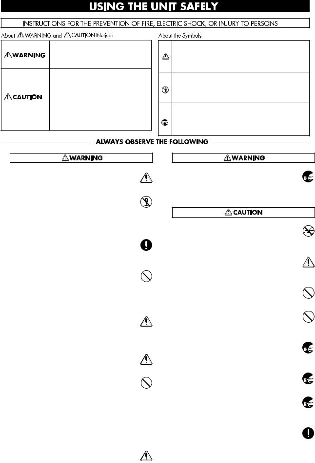
Used for instructions intended to alert the user to the risk of death or severe injury should the unit be used improperly.
Used for instructions intended to alert the user to the risk of injury or material damage should the unit be used improperly.
* Material damage refers to damage or other adverse effects caused with respect to the home and all its furnishings, as well to domestic animals or pets.
● Before using this unit, make sure to read the instructions below, and the Owner’s Manual.
.........................................................................................................
●Do not open or perform any internal modifications on the unit. (The only exception would be where Quick Start manual provides specific instructions which should be followed in order to put in place
user-installable options; see p. 3.)
.........................................................................................................
●Make sure you always have the unit placed so it is level and sure to remain stable. Never place it on stands that could wobble, or on inclined surfaces.
.........................................................................................................
●Avoid damaging the power cord. Do not bend it excessively, step on it, place heavy objects on it, etc. A damaged cord can easily become a shock or fire hazard. Never use a power cord after it has been
damaged.
.........................................................................................................
●In households with small children, an adult should provide supervision until the child is capable of following all the rules essential for the safe opera-
tion of the unit.
.........................................................................................................
● Protect the unit from strong impact.
(Do not drop it!)
.........................................................................................................
●Do not force the unit’s power-supply cord to share an outlet with an unreasonable number of other devices. Be especially careful when using extension cords—the total power used by all devices you have connected to the extension cord’s outlet must never exceed the power rating
(watts/amperes) for the extension cord. Excessive loads can cause the insulation on the cord to heat up and eventually melt through.
.........................................................................................................
● Before using the unit in a foreign country, consult with your dealer, or qualified Roland service personnel.
The symbol alerts the user to important instructions or warnings.The specific meaning of the symbol is determined by the design contained within the triangle. In the case of the symbol at left, it is used for general cautions, warnings, or alerts to danger.
The  symbol alerts the user to items that must never be carried out (are forbidden). The specific thing that must not be done is indicated by the design contained within the circle. In the case of the symbol at left, it means that the unit must never be disassembled.
The ● symbol alerts the user to things that must be carried out. The specific thing that must be done is indicated by the design contained within the circle. In the case of the symbol at left, it means that the powercord plug must be unplugged from the outlet.
●Always turn the unit off and unplug the power  cord before attempting installation of the Hard disk drive unit (HDP88 series) or Effect expansion board VS8F-1.
●Always grasp only the plug on the power-supply cord when plugging into, or unplugging from an outlet.
.........................................................................................................
● Try to prevent cords and cables from becoming entangled. Also, all cords and cables should be placed so they are out of the reach of children.
.........................................................................................................
●Never climb on top of, nor place heavy objects on the unit.
.........................................................................................................
●Never handle the power cord or its plugs with wet hands when plugging into, or unplugging from, an outlet or this unit.
.........................................................................................................
●Before moving the unit, disconnect the power plug  from the outlet, and pull out all cords from exter-
nal devices.
.........................................................................................................
● Before cleaning the unit, turn off the power and  unplug the power cord from the outlet.
.........................................................................................................
● Whenever you suspect the possibility of lightning  in your area, pull the plug on the power cord out
of the outlet.
.........................................................................................................
● When installing the Hard disk drive unit (HDP88 series) or Effect expansion board VS8F-1, remove only the specified screws.
3

Introduction
Thank you for purchasing the Roland VS-880 V-XPANDED Digital Studio Workstation or the VS- 880-S1 System Expansion Kit.
The VS-880 V-XPANDED is a revolution in home studio equipment that makes a cutting-edge studio environment available to the musician. Disk recorder, digital mixer, and multi effects are brought together in a unified system that allows the entire process from recording to mixdown, effects and output to PA equipment to take place entirely in the digital domain.
The VS-880-S1 is an expansion kit that enhances the system software of the VS-880 that you have been using to full V-XPANDED functionality. In addition to the superb digital studio functionality that you have already been enjoying, you will now be able to experience even more powerful functions and even easier operation.
The documentation for VS-880 V-XPANDED consists of two manuals: “Quick Start” and “Owner’s Manual” (this document). If you are using the VS-880 for the first time, please read “Quick Start” first.
About the package contents
■ If you purchased the VS-880 V-XPANDED
The VS-880 V-XPANDED package includes the following items. Make sure that you have all the items.
•VS-880
•Power cable
•Quick Start
•Owner’s Manual (this manual)
•VS8F-1 Preset Patch List
•Leaflet “Notes when using a Zip drive”
•V-XPANDED sticker
■If you purchased the VS-880-S1
The VS-880-S1 package includes the following items. Make sure that you have all the items.
•VS-880-S1 (Zip disk)
•Expanding the functionality of the VS-880
•Owner’s Manual (this manual)
•VS8F-1 Preset Patch List
•V-XPANDED sticker
How this manual is organized
This manual is organized as follows.
■ Chapter 1 Trying out the expanded functions
This chapter provides some simple examples which explain the operation of the expanded VS-880. If you have purchased the VS-880-S1, read this first to learn which functions are added by the V- XPANDED upgrade.
If you purchased the VS-880 V-XPANDED, read the separate “Quick Start” first.
■ Chapter 2 Before you start (VS-880 terminology)
This chapter explains basic concepts that you will need to understand in order to use the VS-880. It also explains various terms that you should know.
■ Chapter 3 Basic operation (as a replacement for a tape MTR)
This chapter explains the actual steps in the procedure of creating a master tape.
4

Introduction
■ Chapter 4 Editing a recorded performance (track editing)
This chapter explains the procedure for “editing sound,” something which was not possible on conventional tape MTR units.
■ Chapter 5 Use with MIDI devices
This chapter explains the procedures for using the VS-880 in conjunction with MIDI devices. Read this chapter when you wish to use the VS-880 in synchronization with other MIDI devices.
■ Chapter 6 Use with a Zip drive
This chapter explains the procedures for using the VS-880 with a Zip drive. Read this chapter when you wish to use a Zip drive to record a performance. This chapter also explains how to use the VS880 with a hard disk or magneto-optical disk.
■ Chapter 7 Use with a DAT recorder
This chapter explains the procedures for using the VS-880 in conjunction with a DAT recorder. Read this chapter when you wish to save your performance on a DAT recorder.
■ Chapter 8 Using the internal effects
This chapter explains the operating procedures when a VS8F-1 effect expansion board is installed. Read the VS8S-1 owner’s manual in conjunction with this chapter.
■ Chapter 9 Other convenient functions
This chapter explains operation of functions which were not discussed in earlier chapters, such as sounding the metronome during recording, or when a foot switch is connected.
■ Chapter 10 Overall settings and status checking
This chapter explains how to make the settings which affect the overall operation of the VS-880.
■ Chapter 11 Taking advantage of the VS-880 (ideas and examples)
This chapter combines some of the functions discussed in earlier chapters, and gives some actual examples of how you can take advantage of the VS-880.
■ Appendices
This chapter contains material which will help you make the best use of the VS-880, such as “Troubleshooting” and “Error message list.”
5

Contents |
|
Main features .................................................................................................................. |
10 |
Important notes .............................................................................................................. |
11 |
Front and rear panels ..................................................................................................... |
13 |
Mixer section .......................................................................................................................................... |
13 |
Recorder section ..................................................................................................................................... |
14 |
Display section ....................................................................................................................................... |
15 |
Rear panel ............................................................................................................................................... |
16 |
Chapter 1 Trying out the expanded functions |
|
Mixer-related .................................................................................................................. |
17 |
Using auto mix ....................................................................................................................................... |
17 |
Using the 3-band equalizer in INPUT MIX/TRACK MIX .............................................................. |
20 |
Mixing in a stereo source (Stereo In) ................................................................................................... |
21 |
Adjusting the level of each track (Track Level) ................................................................................. |
21 |
Causing top panel fader and pan knob operations to take effect immediately ............................ |
21 |
Recorder related functions ............................................................................................. |
22 |
When the Recording mode is set to Mastering .................................................................................. |
22 |
When a digital signal with emphasis is input ................................................................................... |
22 |
Creating a master tape which disables digital copying ................................................................... |
22 |
Effect related .................................................................................................................. |
23 |
Newly added preset patches ................................................................................................................ |
23 |
Newly added algorithms ...................................................................................................................... |
23 |
Adjusting the send level and balance for all effects .......................................................................... |
33 |
Inserting an effect ................................................................................................................................... |
34 |
Display related ................................................................................................................ |
37 |
Holding the level meter peaks ............................................................................................................. |
37 |
Checking the remaining disk capacity ................................................................................................ |
37 |
Disk drive related ............................................................................................................ |
38 |
Checking the reliability of a disk ............................................................................................................... |
38 |
Checking that a disk is not damaged .................................................................................................. |
38 |
Synchronization related .................................................................................................. |
40 |
Assign mark points according to the tempo ...................................................................................... |
40 |
When using the sync track ................................................................................................................... |
40 |
Using the tempo map ............................................................................................................................ |
42 |
Adding an offset to the sync track/tempo map ................................................................................ |
42 |
MIDI related .................................................................................................................... |
43 |
Using program change messages to select scenes ............................................................................ |
43 |
Using program change messages to select effects ............................................................................. |
43 |
Using control change messages to control effects ............................................................................ |
43 |
Other .............................................................................................................................. |
44 |
Using the numeric keys ([NUMERICS]) ............................................................................................. |
44 |
Holding the function of [SHIFT] (Shift Lock) .................................................................................... |
44 |
Easy time adjustment ............................................................................................................................ |
45 |
Chapter 2 Before you start (VS-880 terminology) |
|
Sources, tracks, and channels ....................................................................................... |
46 |
Doing everything in the digital domain (Digital Studio Workstation) ............................... |
46 |
Signal flow (busses) ....................................................................................................... |
46 |
Where a performance is recorded (Song) ...................................................................... |
47 |
Mixer section .................................................................................................................. |
48 |
About mixer modes ............................................................................................................................... |
48 |
Switching the mixer mode .................................................................................................................... |
51 |
Recording the current condition of the mixer (Scene) ...................................................................... |
51 |
Recorder section ............................................................................................................ |
53 |
Differences with a tape-type MTR ...................................................................................................... |
53 |
Number of tracks that can be recorded/played simultaneously ................................................... |
53 |
Virtual tracks provided for each track (V-tracks) ............................................................................. |
53 |
Effects section ................................................................................................................ |
54 |
About the effect expansion board (VS8F-1) ....................................................................................... |
54 |
VS-880 operation ........................................................................................................... |
54 |
How operations are organized (Conditions) ..................................................................................... |
54 |
Switching conditions ............................................................................................................................. |
54 |
6

|
Contents |
Selecting the operation menu .............................................................................................................. |
55 |
Selecting parameters ............................................................................................................................. |
55 |
Modifying the value of settings ........................................................................................................... |
55 |
Executing an operation ........................................................................................................................ |
55 |
Switching the track status (Track Status) ........................................................................................... |
55 |
Changing the current time .................................................................................................................... |
56 |
Storing a time location, method 1 (Locate Point) ............................................................ |
57 |
Storing a time location .......................................................................................................................... |
57 |
Moving to a stored time location ......................................................................................................... |
58 |
Modifying a stored time location ........................................................................................................ |
58 |
Deleting a stored time location ............................................................................................................ |
58 |
Storing a time location, method 2 (Mark Points) ............................................................ |
59 |
Marking a time location ........................................................................................................................ |
59 |
Moving to a marked time location ...................................................................................................... |
59 |
Modifying a marked time location ...................................................................................................... |
60 |
Clearing a mark ...................................................................................................................................... |
60 |
Chapter 3 Basic operation (as a replacement for a tape MTR) |
|
Before you begin ............................................................................................................ |
61 |
When you turn the power on .............................................................................................................. |
61 |
Listening to the demo song ............................................................................................ |
61 |
Listening to the variations of the demo song .................................................................................... |
61 |
Making a new recording ................................................................................................. |
62 |
Specifying the recording mode (Song New) ...................................................................................... |
62 |
Naming the song (Song Name) ............................................................................................................ |
62 |
General procedure for multitrack recording .................................................................... |
63 |
Connect the instruments ....................................................................................................................... |
63 |
Record a performance onto a track ..................................................................................................... |
63 |
Switching V-tracks ................................................................................................................................. |
63 |
Recording additional tracks while listening to the performance (Overdubbing) ........................ |
64 |
Re-recording only your mistakes (Punch-in/out) ............................................................................ |
64 |
Specify beforehand the location for re-recording (Auto punch-in) ................................................ |
65 |
Repeatedly recording over the same area (Loop recording) ........................................................... |
66 |
Combining the performances of two or more tracks into another track (Track bouncing) ........ |
67 |
Creating a master tape .......................................................................................................................... |
67 |
Digital recording ............................................................................................................. |
72 |
Concerning copyright ........................................................................................................................... |
72 |
About SCMS ........................................................................................................................................... |
72 |
Connecting digital devices ................................................................................................................... |
72 |
Matching the sampling frequency ....................................................................................................... |
72 |
Selecting digital input as the source .................................................................................................... |
73 |
When digital recording is not possible ... ........................................................................................... |
73 |
Before you finish operations ........................................................................................... |
74 |
Saving the performance to disk (Song Store) ..................................................................................... |
74 |
Preventing accidental erasure of your performance (Song Protect) ............................................... |
74 |
Selecting a song (Song Select) .............................................................................................................. |
75 |
Turning the power off (Shut Down) ................................................................................................... |
75 |
Re-starting the VS-880 ................................................................................................... |
75 |
Chapter 4 Editing a recorded performance (track editing) |
|
What is editing? .............................................................................................................. |
76 |
Finding a desired location (Preview) ............................................................................... |
76 |
Using [TO] and [FROM] ....................................................................................................................... |
76 |
Scrub playback ([SCRUB]) .................................................................................................................... |
76 |
Basic procedure ............................................................................................................. |
77 |
Re-using part of the performance (Copy) ....................................................................... |
78 |
Modifying the organization of the performance (Move) .................................................. |
79 |
Erasing part of a performance (Erase) ........................................................................... |
81 |
Exchanging performance data between tracks (Exchange) ........................................... |
81 |
Inserting blank space into a performance (Insert) .......................................................... |
82 |
Deleting a portion of a performance (Cut) ...................................................................... |
83 |
Modifying the playback time of the performance (Time compression/expansion) .......... |
84 |
7

Contents
Chapter 5 Use with MIDI devices |
|
About MIDI ..................................................................................................................... |
85 |
What is MIDI .......................................................................................................................................... |
85 |
MIDI connectors ..................................................................................................................................... |
85 |
MIDI channels ........................................................................................................................................ |
85 |
MIDI messages ....................................................................................................................................... |
85 |
MIDI implementation chart .................................................................................................................. |
85 |
Using MIDI to switch the track status ............................................................................. |
86 |
Synchronizing with a MIDI sequencer ............................................................................ |
86 |
Using MTC .............................................................................................................................................. |
86 |
Using the tempo map ............................................................................................................................ |
89 |
Using the sync track .............................................................................................................................. |
91 |
When you experience problems with synchronization ................................................... |
92 |
Chapter 6 Use with a Zip drive |
|
Connecting a Zip drive ................................................................................................... |
93 |
Initializing the disk (Drive Initialize) ................................................................................. |
93 |
Select the Zip drive as the recording destination (Drive Select) ..................................... |
93 |
Saving performance data on a Zip disk (Song Copy) ..................................................... |
94 |
Saving on a single disk (Playable) ....................................................................................................... |
94 |
When the data cannot be saved on a single disk (Archive) ............................................................. |
95 |
If you have problems saving the data ............................................................................. |
96 |
Chapter 7 Use with a DAT recorder (DAT backup) |
|
Saving performance data to a DAT recorder (Backup) .................................................. |
97 |
Loading performance data from a DAT recorder (Recover) ............................................ |
98 |
Checking the names of the performance data that was saved (Name) ......................................... |
99 |
Checking the storage status of performance data that was saved (Verify) ................................... |
99 |
Chapter 8 Using the internal effects |
|
Examples of how the effects can be used .................................................................... |
100 |
Applying reverb to a recorded performance (Loop) ...................................................................... |
100 |
Applying reverb as you record (Loop) ............................................................................................. |
102 |
Applying a vocoder while you record (Insert) ................................................................................ |
104 |
Applying reverb while bouncing tracks (Loop) .............................................................................. |
106 |
If the effect does not sound as you expect ................................................................... |
108 |
Chapter 9 Other convenient functions |
|
Sounding the metronome ............................................................................................. |
109 |
Using an external MIDI sound source to play the metronome ..................................................... |
109 |
Using a foot switch to playback/stop ............................................................................ |
110 |
Stopping automatically (Marker stop) ........................................................................... |
110 |
Changing the pitch during playback (Vari-pitch) ........................................................... |
111 |
Listening only to a specific channel (Solo) ................................................................... |
111 |
Simultaneously adjusting a stereo source (Channel Link) ........................................... |
112 |
Undoing a recording or editing operation ..................................................................... |
112 |
Recording/editing operations which can be undone (Undo) ....................................................... |
112 |
Canceling the last-performed Undo (Redo) ..................................................................................... |
113 |
Canceling only the last-performed operation .................................................................................. |
113 |
When the disk has little remaining space ..................................................................... |
113 |
Deleting only unneeded performance data (Song Optimize) ....................................................... |
113 |
Deleting one song of performance data (Song Erase) .................................................................... |
113 |
Chapter 10 Overall settings and status checking |
|
If the display area is difficult to read (Contrast) ............................................................ |
114 |
Switching the contents of the display (Bar Display) ..................................................... |
114 |
Displaying measures/beats .......................................................................................... |
115 |
Checking the size of a recorded performance .............................................................. |
115 |
Restoring the mixer settings to the initial state ............................................................. |
116 |
If there is no internal hard disk ..................................................................................... |
116 |
8

Contents
Chapter 11 Taking advantage of the VS-880 (ideas and examples)
Recording multiple sources to one track ...................................................................... |
117 |
Collecting just the sections that you like ....................................................................... |
118 |
Copying an 8-track MTR performance to the VS-880 .................................................. |
119 |
Controlling the mixer from a MIDI sequencer ............................................................... |
120 |
Operating the VS-880 from another device (MMC) ...................................................... |
122 |
Synchronizing the operation of two VS-880 units .......................................................................... |
122 |
Operating the VS-880 from an MMC-compatible device .............................................. |
125 |
If you have problems with synchronization .................................................................................... |
126 |
Using external effect units ............................................................................................ |
127 |
Applying an effect during playback ................................................................................................. |
127 |
Applying an effect while you re-record ........................................................................................... |
127 |
Appendices |
|
Using an external disk drive (About SCSI) ................................................................... |
130 |
Troubleshooting ............................................................................................................ |
132 |
Error messages ............................................................................................................ |
134 |
Special key operations ................................................................................................. |
136 |
Parameter list ............................................................................................................... |
138 |
MIDI implementation chart ........................................................................................... |
143 |
Mixer section block diagram ......................................................................................... |
144 |
Glossary ....................................................................................................................... |
145 |
Specifications ............................................................................................................... |
146 |
About the V-XPANDED sticker ..................................................................................... |
147 |
Index ............................................................................................................................. |
149 |
*Iomega is a registered trademark of Iomega Corporation.
*Zip is a trademark of Iomega Corporation.
*All product names mentioned in this document are trademarks or registered trademarks of their respective owners.
9

Main features
■ Digital audio workstation
The digital disk recorder section provides 8 tracks, and allows four tracks to be recorded simultaneously. Each track has eight virtual tracks (V-tracks), allowing a total maximum of 64 tracks to be recorded. This means that you can use convenient techniques such as recording numerous takes of guitar solos, vocals, or chorus.
Editing operations such as copy, move and erase which were impossible for a tape MTR can be easily accomplished. For example, a four-measure drum pattern that was recorded can be repeated several times as a break-beat. Or, you might place the same chorus at the beginning and end of a song.
The VS-880 uses non-destructive editing, a method unique to disk recorders. Previously performed recording or editing operations can be undone up to 999 steps backward (the Undo/Redo function).
Up to eight sets of all mixer settings (scenes) can be stored for each song. When you wish to adjust the balance during mixdown, or to compare effect settings, you can easily recall the previous settings.
For each song, up to 32 time locations (locate points) can be stored. If you register times such as the end of the introduction or the beginning of a break, you will be able to jump immediately to desired points in a song without having to fast-forward or rewind.
Up to 1000 time locations in each song can be marked (mark points). It is useful to place marks at the beginning of each measure, or at locations that you wish to listen to.
A sync track can be created from mark points that were assigned along with the tempo. By transmitting MIDI clock messages according to the sync track, you can easily synchronize the VS-880 with a MIDI sequencer.
Time-based movements of channel faders and pan etc. can be recorded (auto mix). With no additional equipment, the VS-880 can perform mixing operations such as fade in and fade out.
■ Easy-to-operate controls
The VS-880 can be operated as easily as conventional analog multi-track recorders. You will be able to enjoy the advantages of digital recording from the day that you purchase it.
The large LCD screen provides visual confirmation of many settings at once. In particular, the bar display provides a graphical indication of the level meter, pan and fader settings, and the track record status.
■ A full complement of connectors
Four analog audio inputs are provided, and you have the choice of using either 1/4” phone jacks or RCA phono type jacks. The input sensitivity of each jack can be adjusted from line level (+4 dBm) to mic level (-50 dBm). For output, RCA phono type master out jacks (stereo) and AUX send jacks (two output) are provided.
A SCSI connector is standard, allowing you to connect external disk drives such as hard disks or removable disks.
Coaxial type digital I/O connectors are provided, allowing recording/playback of digital audio with another digital audio device (CD player, DAT recorder, MD recorder, etc.)
MIDI connectors (IN, OUT/THRU) allow MIDI messages to be transmitted and received. The VS-880 can be used with a MIDI sequencer for compu-mix, or synchronized with a MIDI sequencer.
In addition to the tracks which record the audio signals, the VS-880 has a sync track which can record MIDI Clock data. By using this sync track, the VS-880 can be synchronized even with a MIDI sequencer which does not implement MTC (MIDI Time Code) or MMC (MIDI Machine Control).
■ A full array of options
If an HDP-88 series hard disk (2.5 inch) is installed internally, the VS-880 will be a self-contained, compact, and portable recording system. In contrast to when external disk drives are used, there will be no possibility of problems resulting from faulty connections. We recommend that you install an internal hard disk when using the VS-880.
If a VS8F-1 effect expansion board is installed, a wide variety of effects will be available for use on the VS-880.
10
Important notes
In addition to the items listed under “IMPORTANT SAFETY INSTRUCTIONS” and “USING THE UNIT SAFELY” on pages 2 and 3, please read and observe the following:
Power Supply
●Do not use this unit on the same power circuit with any device that will generate line noise (such as an electric motor or variable lighting system).
●Before connecting this unit to other devices, turn off the power to all units. This will help prevent malfunctions and/or damage to speakers or other devices.
Placement
●Using the unit near power amplifiers (or other equipment containing large power transformers) may induce hum. To alleviate the problem, change the orientation of this unit; or move it farther away from the source of interference.
●This device may interfere with radio and television reception. Do not use this device in the vicinity of such receivers.
●Do not expose the unit to direct sunlight, place it near devices that radiate heat, leave it inside an enclosed vehicle, or otherwise subject it to temperature extremes. Excessive heat can deform or discolor the unit.
Maintenance
●For everyday cleaning wipe the unit with a soft, dry cloth or one that has been slightly dampened with water. To remove stubborn dirt, use a cloth impregnated with a mild, non-abrasive detergent. Afterwards, be sure to wipe the unit thoroughly with a soft, dry cloth.
●Never use benzene, thinners, alcohol or solvents of any kind, to avoid the possibility of discoloration and/or deformation.
Repairs and Data
●Please be aware that all data contained in the unit’s memory may be lost when the unit is sent for repairs. Important data should always be backed up on a DAT recorder or an external disk drive (e.g., hard disk or MO disk). During repairs, due care is taken to avoid the loss of data. However, in certain cases (such as when circuitry related to memory itself is out of order), we regret that it may not be possible to restore the data, and Roland assumes no liability concerning such loss of data.
Disk drive handling
Disk drives are precision devices. When handling a VS-880 that has an internal hard disk installed, or when handling an external disk drive, observe the following precautions.
●For details on hard disk handling, refer also to the instructions that accompanied your hard disk.
●Before performing the following actions, be sure to perform the shut-down operation. If you fail to perform the shut-down operation, not only the data recorded on the hard disk, but also the hard disk itself may be damaged.
Turning off the power of the disk drive Turning off the power of the VS-880 Removing a disk from a removable disk drive
●While the MIDI/DISK indicator of the VS-880 or the disk drive busy indicator is lit, data is being transferred to or from the disk drive. If you are using a removable disk drive, make sure that this indicator is dark before removing the disk.
●Place the unit in a stable and level location that is not affected by vibration from external sources. If the unit is tilted severely, this may have harmful effects on the operation of the disk drive.
●While using the VS-880, be careful not to subject the unit to vibration or shock, and avoid moving the unit while the power is turned on. When transporting the unit, pack it in its original shipping carton.
●Avoid using the unit immediately after it has been moved to a location with a level of humidity that is greatly different than its former location. Rapid changes in the environment can cause condensation to form inside the drive, which will adversely affect the operation of the drive and/or damage removable disks. When the unit has been moved, allow it to become accustomed to the new environment (allow a few hours) before operating it.
Chapter 1
11

Important notes
Concerning copyright
The law prohibits the unauthorized recording, public performance, broadcast, sale, or distribution etc. of a work (CD recording, video recording, broadcast, etc.) whose copyright is owned by a third party.
The VS-880 does not implement SCMS. This design decision was made with the intent that SCMS should not restrict the creation of original compositions which do not violate copyright law. Roland will take no responsibility for any infringement of copyright that you may commit in using the VS-880.
< About SCMS >
“SCMS” stands for “Serial Copy Management System.” This is a function that protects the rights of copyright holders by prohibiting recording via a digital connection for more than two generations. When digital connections are made between digital recorders that implement this function, SCMS data will be recorded along with the audio data. Digital audio data which contains this SCMS data cannot again be recorded via a digital connection.
Disclaimer of liability
Roland will take no responsibility for any “direct damages,” “consequential damages,” or “any other damages” which may result from your use of the VS-880. These damages may include but are not limited to the following events which can occur when using the VS-880.
Any loss of profit that may occur to you Permanent loss of your music or data
Inability to continue using the VS-880 itself or a connected device
Additional Precautions
●Please be aware that the contents of memory can be irretrievably lost as a result of a malfunction, or the improper operation of the unit. To protect yourself against the risk of loosing important data, we recommend that you periodically save a backup copy of important data you have stored in the unit’s memory on a DAT recorder or an external disk drive (e.g., hard disk or MO disk).
●Unfortunately, it may be impossible to restore the contents of data that was stored on a DAT recorder or an external disk drive (e.g., hard disk or MO disk) once it has been lost. Roland Corporation assumes no liability concerning such loss of data.
●Use a reasonable amount of care when using the unit’s buttons, sliders, or other controls; and when using its jacks and connectors. Rough handling can lead to malfunctions.
●Never strike or apply strong pressure to the display.
●When connecting / disconnecting all cables, grasp the connector itself—never pull on the cable. This way you will avoid causing shorts, or damage to the cable’s internal elements.
●A small amount of heat will radiate from the unit during normal operation.
●To avoid disturbing your neighbors, try to keep the unit’s volume at reasonable levels. You may prefer to use headphones, so you do not need to be concerned about those around you (especially when it is late at night).
●When you need to transport the unit, package it in the box (including padding) that it came in, if possible. Otherwise, you will need to use equivalent packaging materials.
12
Front and rear panels
Mixer section
|
|
|
|
|
|
INPUT SENS |
|
|
|
|
MIXER MODE |
|
PHONES |
|
|
|
|
1 |
PEAK |
2 PEAK |
3 |
PEAK |
4 |
PEAK |
|
|
|
|
|
|
|
|
10 |
|
|
10 |
10 |
|
10 |
|
SELECT |
INPUT |
TRACK |
|
|
|
|
|
|
|
|
|
|
|
|
|
INPUT MIX |
|
|
|
|
|
4 |
50dBm |
4 |
50dBm |
4 |
50dBm |
4 |
50dBm |
|
TRACK MIX |
0 10 |
|
|
|
|
|
|
|
|
||||||||
|
|
|
PAN |
PAN |
|
PAN |
|
PAN |
|
PAN |
PAN |
PAN |
PAN |
AUX SEND |
|
|
|
C |
C |
|
C |
|
C |
|
C |
C |
C |
C |
|
|
|
|
|
|
|
|
|
|
|
|
|
|
|
0 |
|
|
L |
R |
L |
R |
L R |
|
L R |
|
L R |
L R |
L R |
L R |
6dB |
|
|
CH EDIT |
CH EDIT |
CH EDIT |
CH EDIT |
CH EDIT |
CH EDIT |
CH EDIT |
CH EDIT |
EDIT |
||||
|
Input BUSS |
Input BUSS |
V.Track |
EQ Low |
|
EQ Mid |
|
EQ Hi |
Aux Send |
EFFECT-1 |
EFFECT-2 |
SOLO |
||
|
V.Track |
|
|
|||||||||||
|
|
|
|
|
|
|
|
|
|
|
|
|
|
|
|
EQ |
|
|
|
|
|
|
|
|
|
|
|
|
|
|
BUSS Send |
|
|
|
|
|
|
|
|
|
|
|
|
|
|
AUX Send |
|
|
|
|
|
|
|
|
|
|
|
|
Master Out |
|
Channel Link |
|
SEL |
SEL |
|
SEL |
|
SEL |
|
SEL |
SEL |
SEL |
SEL |
|
|
EFFECT -1 |
|
|
|
|
|
|
|
|
|
|
|
|
AUX SEND |
|
-2 |
|
|
|
|
|
|
|
|
|
|
|
|
EFFECT -1 |
|
|
|
|
|
|
|
|
|
|
|
|
|
|
-2 |
|
SOURCE |
STATUS |
STATUS |
STATUS |
|
STATUS |
|
STATUS |
STATUS |
STATUS |
STATUS |
|
||
|
REC |
|
|
|
||||||||||
|
|
|
|
|
|
|
|
|
|
|
|
|
|
|
|
PLAY |
|
|
|
|
|
|
|
|
|
|
|
|
|
|
MUTE |
|
|
|
|
|
|
|
|
|
|
|
|
|
|
|
|
1 |
2 |
|
3 |
|
4 |
|
5 |
6 |
7 |
8 |
MASTER |
|
|
|
BUSS a |
AUX |
|
BUSS |
b |
AUX |
|
BUSS c |
AUX |
BUSS d |
AUX |
|
|
(dB) |
|
|
|
|
|
|
|
|
|
|
|
|
(dB) |
|
6 |
|
|
|
|
|
|
|
|
|
|
|
|
6 |
|
4 |
|
|
|
|
|
|
|
|
|
|
|
|
4 |
|
0 |
|
|
|
|
|
|
|
|
|
|
|
|
0 |
|
4 |
|
|
|
|
|
|
|
|
|
|
|
|
4 |
|
8 |
|
|
|
|
|
|
|
|
|
|
|
|
8 |
|
12 |
|
|
|
|
|
|
|
|
|
|
|
|
12 |
|
18 |
|
|
|
|
|
|
|
|
|
|
|
|
18 |
|
24 |
|
|
|
|
|
|
|
|
|
|
|
|
24 |
|
36 |
|
|
|
|
|
|
|
|
|
|
|
|
36 |
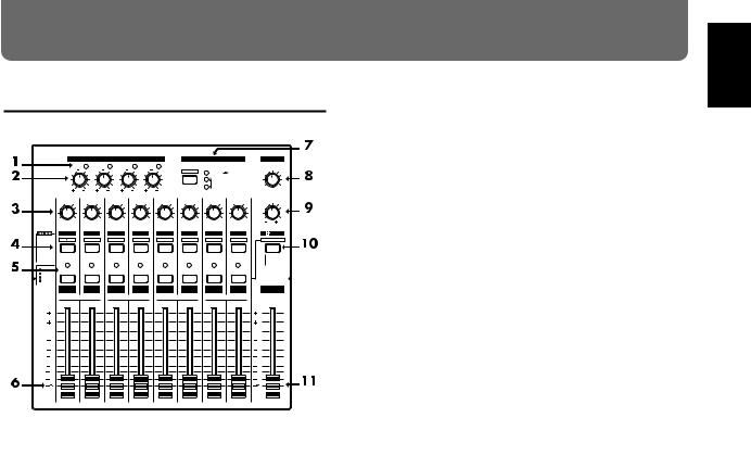
1. |
PEAK indicators |
|
|
|
|
|
|
|
|
|||||
These indicators allow you to avoid distortion of the sound |
||||||||||||||
being input at the input jacks (1–4). The peak indicators will |
||||||||||||||
light red when the signal reaches -6 dB before clipping |
||||||||||||||
level. Adjust the input sensitivity so that the peak indicators |
||||||||||||||
do not light. |
|
|
|
|
|
|
|
|
|
|
|
|||
2. INPUT SENS (input sensitivity) knobs |
|
|
||||||||||||
These knobs adjust the sensitivity of the input jacks (1–4). |
||||||||||||||
Rotate a knob fully right for mic level (-50 dBm), and fully |
||||||||||||||
left for line level (+4 dBm). |
|
|
|
|
|
|
||||||||
3. |
PAN knobs |
|
|
|
|
|
|
|
|
|
|
|||
These knobs adjust the pan (location in the stereo output) of |
||||||||||||||
each channel. |
|
|
|
|
|
|
|
|
|
|
|
|||
4. CH EDIT / SEL (channel edit/select) buttons |
||||||||||||||
Use these buttons when you wish to make settings for a |
||||||||||||||
mixer channel. The names of the parameter groups that can |
||||||||||||||
be set for each channel are printed below CH EDIT. To |
||||||||||||||
directly specify a particular group, you can hold down |
||||||||||||||
[SHIFT] and press the button for that group name. |
||||||||||||||
When editing a song, use these buttons to select tracks for |
||||||||||||||
editing. |
|
|
|
|
|
|
|
|
|
|
|
|
|
|
5. STATUS buttons
These buttons switch the status of each channel. The current status is shown by the button indicator.
SOURCE (orange): The input source assigned to the channel is being output.
REC (blinking red): Recording is selected for the track assigned to the channel.
PLAY (green): The track assigned to the channel will playback.
MUTE (dark): The channel is muted (silent).
6. Channel faders
Use these faders to adjust the volume level of each channel.
7. SELECT button
This button switches the operating mode of the mixer. The current mixer mode is shown by the indicators located at the right of the button. Each time you press the button, you will alternate between INPUT MIX mode and TRACK MIX mode. To change from INPUT TRACK mode to INPUT MIX mode / TRACK MIX mode, hold down [SHIFT] and press the button. Use the same operation to move in the other direction.
INPUT TRACK mode INPUT MIX mode TRACK MIX mode
8. PHONES knob
This knob adjusts the volume of the headphones.
9. AUX SEND knob
This knob adjusts the output level of the AUX SEND jacks.
10. EDIT/SOLO button
Press this button to make settings for the master section of the mixer.
To use the Solo function to monitor only a specific channel, hold [SHIFT] while you press the button.
11. Master fader
Use this fader to adjust the overall output level.
Chapter 1
13
Front and reat panels
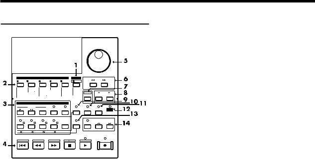
Recorder section
TIME VALUE
VALUE
|
EDIT CONDITION |
|
PLAY |
|
|
|
||
SONG |
LOCATOR |
TRACK |
EFFECT |
SYSTEM |
DISPLAY |
|
PARAMETER |
|
|
|
|
||||||
Song Select |
Marker |
Track Copy |
EFFECT-1 |
System |
Pre Level |
|
|
|
- New |
Locate |
- Move |
-2 |
MIDI |
Post Level |
|
|
|
- Name |
Loop |
- Xchg |
|
DISK |
Play List |
|
|
|
- Copy |
A.Punch I O |
- Insert |
|
Sync |
Fader Pan |
SHIFT |
CURSOR |
|
- Erase |
|
- Cut |
|
Scene |
|
|||
- Optimize |
|
- Erase |
|
Drive Select |
Amp Profile |
|
NO |
YES |
DAT Backup |
|
Time Comp |
Exp. |
- Initialize |
|
|
||
- Recover |
|
|
|
|
|
|
|
|
|
|
LOCATOR |
|
|
|
CANCEL |
ENTER |
|
|
|
|
|
|
|
|
||
|
MARKER |
|
|
|
|
|
|
|
PREVIOUS |
NEXT |
TAP |
LOOP |
AUTO PUNCH |
NUMERICS |
VARI PITCH |
UNDO |
MIDI / |
|
|
|||||||
|
|
|
|
|
|
|
|
DISK |
1 |
2 |
3 |
4 |
5 |
|
|
|
|
|
|
|
|
|
|
|
PREVIEW |
|
LOC 1/ 5 |
LOC 2/ 6 |
LOC 3/ 7 |
LOC 4/ 8 |
CLEAR |
SCENE |
SCRUB |
TO |
FROM |
|
|
|||||||
6 |
7 |
8 |
9 |
0 |
|
|
|
|
1/ 5 |
2 / 6 |
3 / 7 |
4 / 8 |
CLEAR |
|
|
|
|
STORE |
SONG TOP |
SONG END |
SHUT EJECT |
RESTART |
|
|
||
ZERO |
|
REW |
FF |
STOP |
|
PLAY |
|
REC |
1. PLAY/DISPLAY button
Press this button to return from making a setting (edit condition) back to normal status (play condition). To switch display items in the bar display, hold down [SHIFT] and press this button.
2. EDIT CONDITION buttons
The functions and parameters of the VS-880 are organized within these buttons. To use a desired operation, press the appropriate button.
3. LOCATOR buttons
Press these buttons when using the Locator function or the Tap Marker function.
When the NUMERICS indicator is lit, these buttons function as numeric keys to directly input numbers. When the SCENE indicator is lit, these buttons are used to store and recall scenes (snapshots of mixer settings).
4. Transport control buttons
These buttons are used to operate the recorder.
[ZERO]: Return the current time to “00h00m00s00” (zero return).
[REW]: While the button is held down, the current time will be moved backward. This corresponds to the rewind button on a tape recorder.
[FF]: While the button is held down, the current time will be moved forward. This corresponds to the fast-forward button on a tape recorder.
[STOP]: Stop song recording/playback.
[PLAY]: Start song recording/playback from the current time.
[REC]: Press this button to record a song.
5. TIME/VALUE dial
Normally (i.e., in Play condition), this dial is used to move the current time. When making settings (i.e., in Edit condition), this dial is used to modify parameter values.
6. PARAMETER buttons
Use these buttons to switch the parameter display.
7. SHIFT button
This button is used in conjunction with other buttons to access additional functions of that button. For details refer to “Special key operations” (p.136).
8. CURSOR buttons, NO/YES buttons, CANCEL/ENTER buttons
When a YES/NO response is required during an operation, use these button to reply. When two or more parameters are shown in the display, use these buttons to select parameters.
9. NUMERICS button
When this button is pressed to make the indicator light, the ten LOCATOR buttons will act as numeric keys to enter numerical values.
10. VARI PITCH button
Press this button when you wish to change the playback pitch.
11. UNDO button
Press this button to cancel a recording that you have made. Also, after performing a song edit operation, you can press this button to return to the condition before editing. When undo is executed, the button indicator will light.
12. MIDI/DISK indicator
This indicator will light green when MIDI messages are being received, and red when data is being written or read on the disk drive. If both of these are occurring, the indicator will light orange.
13. SCENE button
Press this button when you wish to memorize or recall scenes (snapshots of the mixer settings).
14. PREVIEW button
Press this button to use the Preview function that plays back a specific length before and after the current location.
14
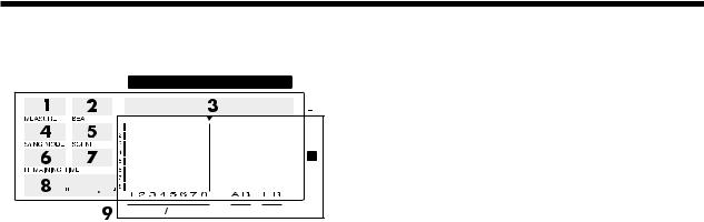
Front and reat panels
Display section
CONDITION MARKER# |
TIME |
||||
|
|
|
|
|
|
dB
0
4
12
24
48
INPUT TRACK |
AUX MASTER |
1. CONDITION
This indicates the current condition.
PLY: Play (normal. When turn the Song Protect on, “Ply” will be indicated.)
CHn: Channel edit (n=1–8, a–d) (in INPUT TRACK MIX mode)
INn: Channel edit (n=1–6, a–c) (in INPUT MIX mode) TRn: Channel edit (n=1–8, a–d) (in TRACK MIX mode) MST: Master block edit
SNG: Song edit LOC: Locator edit TRK: Track edit EFF: Effect edit SYS: System edit
*The channel edit display will depend on the currently selected mixer mode. Also, channels for which Channel Link is OFF will be displayed as 1–8, and channels for which it is ON will be displayed as a–d.
2. MARKER
This shows the mark point number for the current time. If a mark point has not been assigned to the current time, the closest mark point number located before the current time will be shown.
3. TIME
This shows the current time of the song.
4. MEASURE
This shows the current measure of the song.
5. BEAT
This shows the current beat of the song.
6. SYNC MODE
This indicates the current sync mode (method of synchronization).
7. SCENE
This shows the currently used scene number (mixer setting). An asterisk “ ” shown at the beginning of the scene number indicates that the current mixer settings have been modified since the scene was recalled.
8. REMAINING TIME
This shows the remaining length of time available for recording.
9. Bar display
In Play condition, the item selected by [DISPLAY (PLAY)] are shown graphically. While you are making a setting, data for the setting being made is displayed graphically.
15
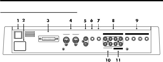
Front and reat panels
Rear panel
SCSI |
MIDI |
DIGITAL(5,6) |
FOOT PHONES |
|
INPUT B |
|
|
|
INPUT A |
|
|
OUT THRU |
IN |
IN |
SWITCH |
4 |
3 |
2 |
1 |
4 |
3 |
2 |
1 |
AC IN |
|
|
|
|
|
|
|
|
|
|
|
|
|
OUT |
|
B |
A |
R |
L |
|
|
|
|
|
|
|
|
AUX SEND |
MASTER OUT |
|
|
|
|
||
1. POWER switch
This switch turns the VS-880 power on/off.
2. AC IN (AC inlet)
Connect the included power cable here.
3. SCSI connector
This is a DB-25 type SCSI connector for connecting disk drives such as hard disks or removable disks. If you wish to connect a disk drive, refer to “Use with a Zip drive” (p.93).
4. MIDI connectors (IN, OUT/THRU)
External MIDI devices (MIDI controllers, MIDI sequencers, etc.) can be connected here.
IN: This connector receives MIDI messages. Connect it to the MIDI OUT connector of the external MIDI device.
OUT/THRU: This connector can be used either as a MIDI OUT or as a MIDI THRU connector. With the factory settings, it will function as a MIDI OUT connector.
5. DIGITAL (5,6) connectors (IN, OUT)
These are coaxial-type digital I/O connectors (comforms to S/P DIF).
IN: This inputs a digital audio signal (stereo).
OUT: This outputs a digital audio signal (stereo). The sound is the same as that of the MASTER OUT jacks.
*To record a digital audio signal, it is not sufficient to simply connect a digital audio device to the DIGITAL IN connector. When inputting a digital audio signal, refer to “Digital recording” (p.72).
*The DIGITAL connector is not able to input or output analog audio signals.
6. FOOT SWITCH jack
An optional foot switch can be connected here to control recorder operations, mark point settings, and punch in/out operations etc. by foot switch. With the factory settings, a foot switch will start/stop the recorder. To change this function, refer to “Using a footswitch to playback/stop” (p.110).
7. PHONES jack
An optional set of headphones can be connected here. The PHONES jack outputs the same sound as the MASTER OUT jack.
8.INPUT B jacks (1–4)
9.INPUT A jacks (1–4)
These are input jacks for analog audio signals. INPUT A are 1/4” phone jacks, and INPUT B are RCA phono jacks. You may use either type of jack. If cables are connected to both types, the INPUT A jacks will take priority. Use the INPUT SENS knob to adjust the input sensitivity of each input.
10.AUX SEND jacks (A,B)
11.MASTER OUT jacks (L,R)
These are output jacks for analog audio signals (RCA phono type).
With the factory settings, all signals will be output from the MASTER OUT jacks, and there will be no output from the AUX SEND jacks. The output will be determined by the settings of the mixer’s master section and the settings of each channel.
The AUX SEND jacks can also be used as send jacks for connecting external effect units (p.127).
16

Chapter 1 Trying out the expanded functions
This chapter provides some simple examples which explain the operation of the expanded VS-880. Read the explanations in sequence to learn about the newly added functions.
*If a song created on the VS-880 V-XPANDED is loaded by VS-880 Ver.1, data for the functions added in V-XPAND- ED (Auto Mix etc.) may be lost. To prevent this from happening, turn Song Protect on (p.74).
Mixer-related
■ Using auto mix
Time based movements such as channel faders and pan can now be recorded to mark points (auto mix). When you move to a mark point, the recorded mixer settings will be reproduced.
Auto mix can be recorded separately in each mixer mode. The mixer settings which can be recorded are as follows.
*The items printed in bold type can be adjusted directly from the faders or pan knobs on the top panel. By operating these while a song is playing back, you can record time-based mixer movements such as fade-in or panning. When Channel Link is on, the channel faders and pan knobs of even-numbered channels will respectively adjust AUX level and AUX balance.
Master Block
MasterLevel
Master Bal (Master Balance)
AUX Level
AUX Bal (AUX Balance)
EFFECT1 SND Lev (Effect 1 Send Level)
EFFECT1 SND Bal (Effect 1 Send Balance)
EFFECT1 RTN Lev (Effect 1 Return Level)
EFFECT1 RTN Bal (Effect 1 Return Balance)
EFFECT2 SND Lev (Effect 2 Send Level)
EFFECT2 SND Bal (Effect 2 Send Balance)
EFFECT2 RTN Lev (Effect 2 Return Level)
EFFECT2 RTN Bal(Effect 2 Return Balance)
Effect
EFFECT-1 (Effect 1 Number)
EFFECT-2 (Effect 2 Number)
< How auto mix differs from scenes >
In that auto mix “records mixer settings,” its functionality is similar to scenes.
It differs from scenes in the following ways. Use the two functions as appropriate for your needs.
1000 can be recorded (the number of mark points). Valid even during song playback.
Cannot switch the mixer mode. Cannot switch V-tracks.
INPUT TRACK
MIX Level
MIX Pan/MIX Bal (Mix Balance)
AUX Level
AUX Pan/AUX Bal (AUX Balance)
EFFECT1 Send (Effect 1 Send Level)
EFFECT1 Pan/EFFECT1 Bal (Effect 1 Balance)
EFFECT2 Send (Effect 2 Send Level)
EFFECT2 Pan/EFFECT2 Bal (Effect 2 Balance)
INPUT MIX
BUSS Level
BUSS Pan/BUSS Bal (BUSS Balance)
AUX Level
AUX Pan/AUX Bal (AUX Balance)
EFFECT1 Send (Effect 1 Send Level)
EFFECT1 Pan/EFFECT1 Bal (Effect 1 Balance)
EFFECT2 Send (Effect 2 Send Level)
EFFECT2 Pan/EFFECT2 Bal (Effect 2 Balance)
TRACK MIX
BUSS Level
BUSS Pan/BUSS Bal (BUSS Balance)
AUX Level
AUX Pan/AUX Bal (AUX Balance)
EFFECT1 Send (Effect 1 Send Level)
EFFECT1 Pan/EFFECT1 Bal (Effect 1 Balance)
EFFECT2 Send (Effect 2 Send Level)
EFFECT2 Pan/EFFECT2 Bal (Effect 2 Balance)
Chapter 1
17

Chapter 1 Trying out the expanded functions
Preparations for auto mix
1.Press [SYSTEM] several times until “SYS Scene/Auto Mix?” is displayed.
2.Press [YES].
3.Press PARAMETER [  ] several times until “SYS A.Mix Mode=” appears.
CONDITION MARKER# |
TIME |
dB
0
4
12
24
48
INPUT TRACK |
AUX MASTER |
4.Rotate the TIME/VALUE dial.
When the setting is on, the [SELECT] indicator will blink.
A.Mix Mode (Auto mix mode)
Off: Auto mix mode will not be used (same as in Ver.1). On: Auto mix mode will be used.
5.Press [PLAY(DISPLAY)].
Return to Play condition.
*By holding down [SCENE] and pressing [SELECT], you can turn Auto Mix Mode on/off in a single operation.
Recording the mixer settings, method 1 (Snapshot)
Mixer settings can be recorded in a Mark point. When you move to that Mark point, the mixer settings that were recorded will be reproduced.
For example, this is convenient when you want the intro and ending to have different volume levels for the guitar part or different effect send levels etc.
1.Make sure that Auto Mix is on, press holding down [SCENE] and pressing [TAP].
A mark point will be added at the current time location. At the same time, the settings of the mixer will be recorded at the mark point. A mark point in which mixer settings are recorded will be indicated by an “ ” following it.
CONDITION MARKER# |
TIME |
dB
0
4
12
24
48
INPUT TRACK |
AUX MASTER |
*If a mark point already exists within 0.1 seconds before the time location at which you are attempting to place a new mark point (i.e., the current time), the auto mix data will be recorded at the earlier mark point. A mark point will not be newly assigned.
Recording the mixer settings, method 2 (Gradation)
This method creates an auto mix that smoothly connects the mixer settings recorded in two adjacent mark points.
For example, this is convenient when you wish to fade-in or fade-out at a specified time.
1.Move to the time location at which you wish to begin the auto mix.
2.Perform the procedure for “Recording the mixer settings, method 1”.
3.Move to the time location at which you wish to end the auto mix.
4.Perform the procedure for “Recording the mixer settings, method 1” once again.
Two mark points have now been assigned.
5.Make sure that auto mix is on, holding down [SCENE] and pressing [PREV].
A mark point will be automatically added between the two mark points, and the mixer settings will be interpolated.
*If you wish to interpolate with the previous mark point, press [SCENE]+[PREV]. If you wish to interpolate with the next mark point, holding down [SCENE] and pressing [NEXT].
Recording the mixer settings, method 3 (Realtime)
With this method, only those the mixer settings which can be adjusted from the top panel will be recorded to mark points in realtime. For example, this is convenient when you wish to fade-in or fade-out individual tracks.
1.Move to the time location at which you wish to record the auto mix.
2.Make sure that auto mix is on, holding down [SCENE] and pressing [REC].
The CONDITION column display will alternate between the current condition name and “mix,” indicating that preparations have been made for realtime recording of the auto mix.
3.Specify the channels for with auto mix will be recorded. Move the faders and pan knobs of the top panel to the desired locations.
4.Press [PLAY].
Playback will begin.
5.Operate the channel faders, pan knobs, and master fader of the top panel.
Auto mix data will be recorded only for those channels which were modified.
6.When the mix is finished, press [STOP].
Mark points will be automatically created in the area which was played back.
If you wish to redo the auto mix, repeat steps 1–5.
18
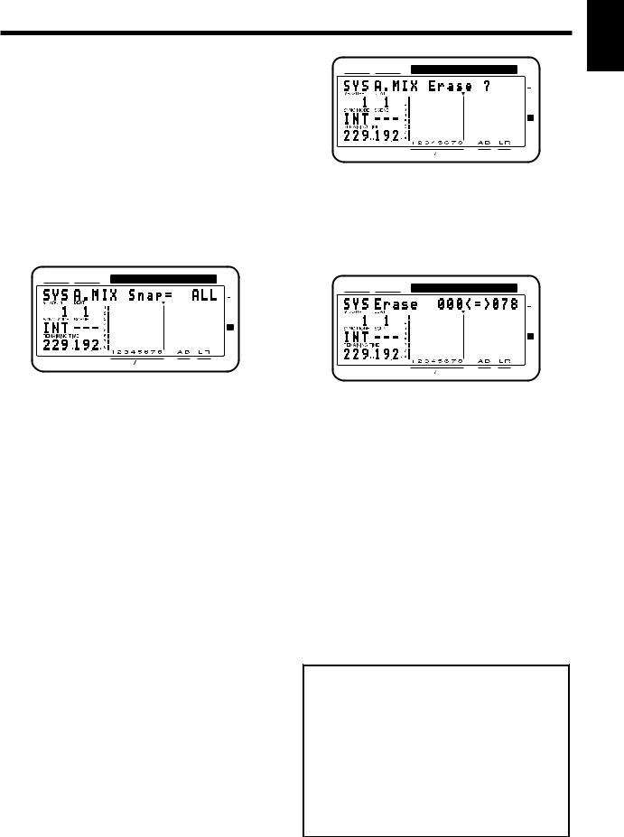
Chapter 1 Trying out the expanded functions
If you do not wish to record top panel settings (Mask Fader)
In “Recording the mixer settings, method 1 (Snapshot)”, you can specify that the settings adjustable from the top panel will not be recorded.
For example, this is convenient when you have made fadein settings according to “Recording the mixer settings, method 2”, and then wish to modify the effect send levels, etc.
CONDITION MARKER# |
TIME |
dB
0
4
12
24
48
INPUT TRACK |
AUX MASTER |
1.Press [SYSTEM] several times until “SYS Scene/Auto Mix?” appears.
2.Press [YES].
3.Press PARAMETER [  ] several times until “SYS A.Mix Snap=” appears.
CONDITION MARKER# |
TIME |
dB
0
4
12
24
48
INPUT TRACK |
AUX MASTER |
5.Use the TIME/VALUE dial to specify the first mark point of the area in which you wish to erase the auto mix.
6.Press CURSOR[  ].
].
The cursor will move toward the right.
7.Use the TIME/VALUE dial to specify the last mark point of the area in which you wish to erase the auto mix.
CONDITION MARKER# |
TIME |
dB
0
4
12
24
48
INPUT TRACK |
AUX MASTER |
4. Rotate the TIME/VALUE dial.
A.Mix Snap (Auto Mix Snapshot Mode)
Select the settings that will be recorded by the snapshot. All: All settings will be recorded.
MaskF: Settings which can be adjusted by the top panel (channel faders etc.) will be ignored.
5.Press [PLAY(DISPLAY)]. You will return to Play condition.
6.Perform the procedure of “Recording the mixer settings, method 1”.
Playing back the auto mix
1.Make sure that auto mix is on.
2.Press [PLAY].
The auto mix will playback.
While the auto mix is playing back, operating a fader or pan knob will cause auto mix to be defeated for that channel. If you stop and then playback again, auto mix will once again take effect. Alternatively, you can temporarily turn Auto Mix off during playback and then turn it on again, causing Auto Mix to again be valid.
Erasing the auto mix
1.Press [SYSTEM] several times until “SYS Scene/Auto Mix?” appears.
2.Press [YES].
3.Press PARAMETER [  ] several times until “SYS A.Mix Erase?” appears.
4.Press [YES].
8.Press PARAMETER [  ].
].
The display will indicate “SYS EraseMode=”.
9.Rotate the TIME/VALUE dial.
EraseMode (Auto Mix Erase Mode)
Select the auto mix data which will be erased. Event: Only auto mix events will be erased.
Marker: Both mark points and auto mix events will be erased.
10.Press PARAMETER [  ].
].
The display will indicate “SYS Erase___<=>___?”. The underlined area will display the mark points specified in steps 5–7.
11.Press [YES].
A message will ask you to confirm that you really wish to erase the data.
12.Press [YES] once again.
The auto mix will be erased.
< What is an event? >
The smallest unit of memory used by the VS-880 to store recorded results on disk is the event. A newly created song provides approximately 12,000 events per song.
For each track, one recording pass uses two events. Operations such as punch-in/out or track copy also use up events. The number of events that are used up will fluctuate in a complex way. For example, auto mix uses up five events for each mark point.
Even if there is capacity remaining on the disk, further recording or track editing will not be possible if all of the events are used up. In such cases, an error message such as “Event Mem Full” will appear (p.134).
Chapter 1
19
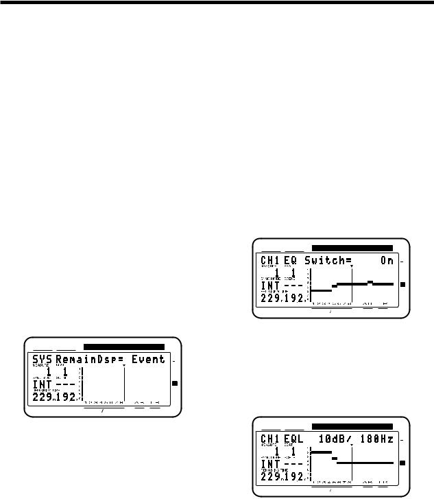
Chapter 1 Trying out the expanded functions
About “!!! Lack of EVENT !!” display
“!!! Lack of EVENT !!” will be appeared in the display in the following cases, and you cannot continue the current operation.
•If you push [SCENE]+[REC] buttons to record AutoMix data in realtime, when the remaining number of EVENT is less than 1000.
•If you try to UNDO or REDO when the remaining number of Event is less than 200.
The smallest unit of memory used by the VS-880 to store recorded results on disk are the events. A newly created song provides approximately 12,000 events per song.
For each track, one recording pass uses two events. Operations such as punch-in/out or track copy also use up events. The number of events that are used up will fluctuate in a complex way. For example, auto mix uses up five events for each mark point.
When you do a lot of recording, editing (Track Copy, Track Move) or record AutoMix of long period, please check the remaining number of Events frequently. Procedure is as follows.
1.Press [SYSTEM] several times until “SYS System PRM?” appears.
2.Press [YES].
3.Press PARAMETER [  ] several times until “SYS RemainDsp=” appears.
4.Select “Event” with TIME/VALUE dial.
CONDITION MARKER# |
TIME |
dB
0
4
12
24
48
INPUT TRACK |
AUX MASTER |
Remaining number of Events can be saved with the following procedures. Please try the most appropriate one with your situation.
•Execute Song Store (Owner's manual p.74)
Please Execute Song Store if in UNDO condition ([UNDO] indicator is lit.). Events served for REDO will be released. But please note that you cannot cancel (REDO) the last UNDO if you once execute STORE.
•Execute Song Optimize (Owner's manual p.113)
Please execute Song Optimize if you have done a lot of Punch In recording. Events served for unnecessary audio data will be released. But please note that you can only do single level UNDO.
•Erace AutoMix data (Owner's manual p.19)
If you have recorded AutoMix data, erase unnecessary data. Events served for unnecessary AutoMix data will be released.
■ Using the 3-band equalizer in
INPUT MIX/TRACK MIX
From the total of fourteen INPUT MIX/TRACK MIX channels, you can now use a 3-band equalizer on any eight selected channels.
*If equalizer is turned on for more than 8 channels, it will not be possible to use the 3-band equalizer. Please turn off the equalizer switch for channels on which equalization is not required.
Turning the equalizer on/off
1.Make sure that the mixer mode is INPUT MIX/TRACK MIX.
2.Hold down [SHIFT], and press channel 3 [EQ Low(CH EDIT)].
3.Press PARAMETER [  ].
].
4.Press [CH EDIT] for the channels or tracks for which you wish to turn the equalizer off.
CONDITION MARKER# |
TIME |
dB
0
4
12
24
48
INPUT TRACK |
AUX MASTER |
5. Rotate the TIME/VALUE dial.
EQ Switch (equalizer switch)
If you wish to use the equalizer, set this “On.” If not, set this “Off.” When equalizer settings are being made, the equalization curve will be shown graphically in the bar display. If this is “Off” the equalizer-related parameters will not be available.
CONDITION MARKER# |
TIME |
dB
0
4
12
24
48
INPUT TRACK |
AUX MASTER |
20
Chapter 1 Trying out the expanded functions
Using the 3-band equalizer
1.Make sure that the mixer mode is INPUT MIX/TRACK MIX.
If it is INPUT TRACK, holding down [SHIFT] and pressing [SELECT].
2.Press [EDIT(SOLO)] several times until “MST EQ Sel=” appears.
3.Rotate the TIME/VALUE dial.
EQ Sel (Equalizer Select)
Select the type of equalizer that you wish to use.
2BandEQ: 14 channels of 2-band equalizers (same as Ver.1).
3BandEQ: 8 channels of 3-band equalizers.
■ Mixing in a stereo source
(Stereo In)
Even when playing back all 8 tracks in INPUT TRACK, you can now mix in a stereo source for output to master out.
For example, this is convenient when two VS-880 units are being operated in synchronization.
1.Press [EDIT(SOLO)] several times until “MST StereoIn=” appears.
2.Select the input source for the stereo source. Rotate the TIME/VALUE dial.
StereoIn (Stereo In)
Off: Stereo In will not be used.
Input12: Inputs 1 and 2 will be input in stereo. Input34: Inputs 3 and 4 will be input in stereo. Digital: The digital input will be input in stereo.
3.Press PARAMETER [  ].
].
The display will indicate “MST StIn Level=”.
4.Adjust the volume level of the stereo input. Rotate the TIME/VALUE dial.
5.Press PARAMETER [  ].
].
The display will indicate “MST StIn Bal=”.
6.Adjust the left/right balance of the stereo input. Rotate the TIME/VALUE dial.
■ Adjusting the level of each track
(Track Level)
It is now possible to adjust the volume level of each track independently from the channel faders.
For example, this is convenient when you wish to raise the track level for playback of a track which was recorded at a low volume level.
1.Press [CH EDIT] for the track whose volume you wish to adjust.
2.Press PARAMETER [  ] several times until “TrackLevel=” appears.
3.Rotate the TIME/VALUE dial.
TrackLevel (Track Level)
The volume level of each track can be adjusted over a range of -12–12dB.
■Causing top panel fader and pan knob operations to take
effect immediately
When the volume or pan has been adjusted in Channel Edit condition, switching between INPUT MIX and TRACK MIX can cause the fader or pan knob locations to no longer match the actual volume level or pan. In such cases, an “ ” symbol will be appended to the displayed values of the settings. Also, when the fader or pan locations are shown in the bar display, the current channel fader locations will blink.
1.Press [SYSTEM] several time until “SYS System PRM ?” appears.
2.Press [YES].
3.Press PARAMETER [  ] several times until “SYS FaderMatch” appears.
4.Rotate the TIME/VALUE dial.
FaderMatch (Fader Match)
Select how the faders will act when the fader or pan knob locations do not match the actual volume level or panning.
Null: Changes will not occur until the channel fader or pan knob is moved to the actual value (same as Ver.1).
Jump: The actual value will change at the instant that the fader or pan knob is moved.
5.Press [PLAY(DISPLAY)].
You will return to Play condition.
Chapter 1
21
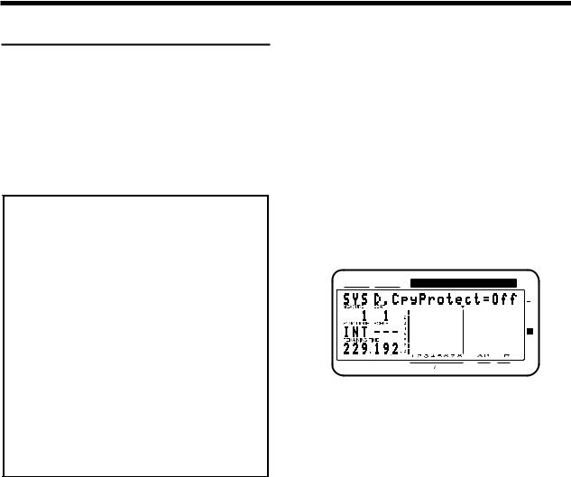
Chapter 1 Trying out the expanded functions
Recorder related functions
■ When the Recording mode is set to Mastering
When the Recording mode (p.62) is set to Mastering (MAS), it is now possible to playback up to six tracks simultaneously. At this time, the VS-880 will function as a 6-track recorder (tracks 1-6). Tracks 7–8 cannot be used.
Previously, only four tracks could be played back simultaneously when the Recording mode was set to Mastering (MAS).
< When using a Zip drive >
A Zip drive is not able to read or write data with sufficient speed. For this reason, when it is being used as the current drive (i.e., the drive for recording or playback), it will not be possible to playback six tracks simultaneously. Refer to the following table, and limit the number of simultaneously played back tracks accordingly. For details refer to the enclosed leaflet “Notes when using a Zip drive.”
*Numbers are guidelines for numbers of tracks that can be played back simultaneously.
Numbers in parentheses ( ) are guidelines for numbers of tracks in song in which operations such as punch-in recording or track copy are performed repeatedly.
Recording mode |
Sample rate |
|
|
|
|
48.0kHz |
44.1kHz |
32.0kHz |
|
Mastering |
3(2) |
4(2) |
5(4) |
|
Multitrack 1 |
7(6) |
7(5) |
8(6) |
|
Multitrack 2 |
7(6) |
8(7) |
8(8) |
|
Live |
8(8) |
8(8) |
8(8) |
|
■ When a digital signal with emphasis is input
When a digital signal with emphasis is input from the digital in connector, it will be automatically de-emphasized.
■ Creating a master tape which disables digital copying
When digitally mixing down from the VS-880 to a DAT recorder etc., you can now prohibit digital copies from being made from the mixdown tape.
For example, a single-generation of digital recording from a CD player to a DAT recorder is permitted. It will not be possible to make a digital copy from the digitally-recorded DAT to another digital device (p.72). This function causes a tape which is digitally recorded from the VS-880 to behave in the same way as a tape digitally recorded from a CD.
1.Press [SYSTEM] several times until “SYS System PRM?” appears.
2.Press [YES].
3.Press PARAMETER [  ] several times until “SYS D.CpyProtect=” appears.
CONDITION MARKER# |
TIME |
dB
0
4
12
24
48
INPUT TRACK |
AUX MASTER |
4.Rotate the TIME/VALUE dial. If you wish to prohibit digital copying, turn the setting on.
D.CpyProtect (Digital Protect Switch)
Specify whether or not digital copying of a digitally-mixed down tape will be permitted or not.
Off: Digital copying will be permitted (same as Ver.1). On: Digital copying will be prohibited.
5.Press [PLAY(DISPLAY)].
You will return to Play condition.
6.Digitally mixdown from the VS-880 to a DAT recorder etc. (p.73).
It will not be possible to digitally copy this master tape to another DAT recorder etc.
22
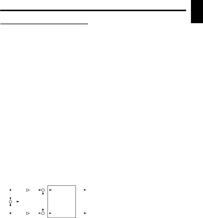
Chapter 1 Trying out the expanded functions
Effect related
When a VS8F-1 effect expansion board is installed, a single VS-880 now allows you to use two stereo effects.
Please read the VS8F-1 owner’s manual together with this explanation.
■ Newly added preset patches
One hundred preset patches have been added to the effect patches. Refer to the included “Preset Patch List.”
Due to the increased number of preset patches, the patch numbers have changed as follows.
Ver.1 |
V-XPANDED |
Preset 001–100 |
Preset A00–A99 |
(newly added) |
Preset B00–B99 |
User 001–100 |
User U00–U99 |
■ Newly added algorithms
The following effect algorithms have been added.
Reverb 2 (p.23)
Space Chorus (p.24)
Lo-Fi Processor (p.25)
4-Band Parametric Equalizer (p.26)
10-Band Graphic Equalizer (p.27)
Hum Canceler (p.28)
Vocal Canceller (p.28)
Vocoder 2 (p.29)
Voice Transformer (p.30)
Mic Simulator (p.32)
● Reverb 2
This is a reverb that provides a gating function and a ducking function. It can be used in either EFFECT-1 or EFFECT- 2. You can use two reverbs with different settings, or use it in combination with a previous reverb.
|
Input L |
Direct Level |
|
|
Output L |
||||||||||
|
|
|
|
|
|
|
|
|
|
|
|
|
Equalizer |
|
|
|
|
|
|
|
|
|
|
|
|
|
|
|
|
|
|
|
|
|
|
|
|
|
|
|
|
|
|
|
|
|
|
|
|
|
|
|
|
|
|
|
|
|
|
|
|
|
|
|
|
|
|
|
|
|
|
|
|
|
|
|
|
|
|
|
|
|
|
|
|
|
|
|
|
|
|
|
|
|
|
|
|
|
|
|
|
|
Reverb |
|
|
|
|
|
|
|
|
|
|
|
|
|
|
|
|
|
|
|
|
|
|
|
|
|
|
|
|
|
|
|
|
|
|
|
|
|
|
|
|
|
|
|
|
|
|
|
|
|
|
|
|
|
|
|
|
|
|
|
|
|
|
|
|
|
|
|
|
|
Equalizer |
|
|
|
Input R |
Direct Level |
|
Output R |
|||||||||||
|
|
|
|||||||||||||
|
|
|
|||||||||||||
REV (Reverb) |
|
|
|
||||||||||||
|
Reverb |
On, Off |
|
|
|
||||||||||
|
Type |
Room1, Room2, Hall1, Hall2, Plate |
|||||||||||||
|
Time |
0.1–10.0 sec |
|
|
|
||||||||||
|
PreDLY |
0–200 msec |
|
|
|
||||||||||
|
Density |
0–100 |
|
|
|
||||||||||
|
HPF |
Thru, 20–2000 Hz |
|
|
|
||||||||||
|
LPF |
1.0–20.0 kHz, Thru |
|
|
|
||||||||||
|
EFLevel |
0–100 |
|
|
|
||||||||||
|
DiLevel |
0–100 |
|
|
|
||||||||||
|
Gate |
Off, On |
|
|
|
||||||||||
Mode |
Gate, Ducking |
Thresh |
0–100 |
Attack |
1–100 |
Release |
1–100 |
HoldTime |
1–100 |
Reverb
Turn reverb on/off. When turned off, the following items will not be displayed.
Type (Reverb Type)
Select the type of reverb.
Room1: Normal room reverb.
Room2: Room reverb with a softer tone than Room1. Hall1: Normal hall reverb.
Hall2: Hall reverb with a softer tone than Hall1. Plate: Plate reverb.
Time
Adjust the length (time) of the reverberation.
PreDLY (Pre delay)
Adjust the time until the reverb is output.
Density
Adjust the density of the reverb.
HPF (High pass filter)
Adjust the frequency at which the high pass filter will begin to take effect. With a setting of Thru, the high pass filter will not function.
LPF (Low pass filter)
Adjust the frequency at which the low pass filter will begin to take effect. With a setting of Thru, the low pass filter will not function.
EFLevel (Effect level)
Adjust the volume of the reverb.
DiLevel (Direct level)
Adjust the volume of the direct sound.
Gate
Turn the gate function on/off. When this is off, the following items will not be displayed.
Mode (Gate mode)
Select the way in which the gate function will operate. Gate: The gate will begin to open when the direct
signal level exceeds the threshold level, and will begin to close when it falls below the threshold level.
Ducking: The function will be the opposite of the Gate setting. The gate will begin to close when the direct signal level exceeds the threshold level, and will begin to open when it falls below the threshold level.
Thresh (Threshold)
Adjust the basic level at which opening and closing of the gate will be controlled.
Chapter 1
23

Chapter 1 Trying out the expanded functions
Attack
Adjust the time from when the direct sound level exceeds the threshold level until when the gate is completely open.
Release
Adjust the time from when the hold time has elapsed until the sound is completely muted.
HoldTime
Adjust the time from when the input falls below the threshold level until when the release begins.
EQ (Equalizer)
EQ |
Off, On |
LowType |
Shlv, Peak |
Low.G |
-12–12 dB |
Low.F |
20–2000 Hz |
Low.Q |
0.3–10 |
Mid.G |
-12–12 dB |
Mid.F |
200–8000 Hz |
Mid.Q |
0.3–10 |
HiType |
Shlv, Peak |
Hi.G |
-12–12 dB |
Hi.F |
1.4–20.0 kHz |
Hi.Q |
0.3–10 |
OutLevel |
0–100 |
EQ (Equalizer)
Turn the equalizer on/off. If this is turned off, the following items will not be displayed.
LowType
Select the type of the low range equalizer.
Shlv: |
Shelving type |
Peak: |
Peaking type |
Low.G (Low gain)
Specify the gain (amount of boost/cut) for the low range equalizer.
Low.F (Low frequency)
Specify the center frequency of the low range equalizer.
Low.Q (Low Q)
Specify the width of the band around the center frequency specified for the low range equalizer in which the gain adjustment will occur. As this setting is raised, the width of the band affected will become narrower.
Mid.G (Middle gain)
Specify the gain (amount of boost/cut) for the mid-range equalizer.
Mid.F (Middle frequency)
Specify the center frequency of the mid-range equalizer.
Mid.Q (Middle Q)
Specify the width of the band around the center frequency specified for the middle range equalizer in which the gain adjustment will occur. As this setting is raised, the width of the band affected will become narrower.
HiType (High type)
Select the type of high range equalizer.
Shlv: |
Shelving type |
Peak: |
Peaking type |
Hi.G (High gain)
Specify the gain (amount of boost/cut) for the high range equalizer.
Hi.F (High frequency)
Specify the center frequency of the high range equalizer.
Hi.Q (High Q)
Specify the width of the band around the center frequency specified for the high range equalizer in which the gain adjustment will occur. As this setting is raised, the width of the band affected will become narrower.
OutLevel (Output level)
Adjust the volume level after the sound has passed through the equalizer.
● Space Chorus
This is a chorus which simulates the Roland SDD-320.
Input L |
|
Output L |
||
|
|
Space Chorus |
|
|
Input R |
|
Output R |
||
|
||||
SCH (Space Chorus)
SpaceCho |
Off, On |
InMod |
Mono, Stereo |
Mode |
1, 2, 3, 4, 1+4, 2+4, 3+4 |
MixBal |
0–100 |
SpaceCho (Space Chorus)
Turn space chorus on/off. If this is turned off, the following items will not be displayed.
InMod (Input mode)
Specify whether the input signal is stereo or mono.
Mode (Space mode)
Select the way in the chorus will change.
MixBal (Mix balance)
Adjust the balance between the chorus volume and the direct sound volume.
24
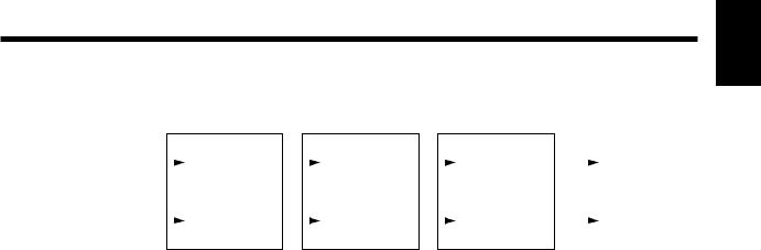
Chapter 1 Trying out the expanded functions
● Lo-Fi Processor
This allows you to create a “lo-fi” sound by lowering the sample rate and/or decreasing the number of bits. Realtime modify filters connected in series allow you to reshape the sound freely.
Input L |
|
|
|
|
|
|
|
Output L |
||
Lo-Fi |
|
|
Realtime |
|
|
Noise |
|
|
||
|
|
|
|
|
|
|
|
|||
|
|
Processor |
|
|
Modify Filter |
|
|
Suppressor |
|
|
|
|
|
|
|
|
|
|
|
|
|
|
|
|
|
|
|
|
|
|
|
|
|
|
Lo-Fi |
|
|
Realtime |
|
|
Noise |
|
|
Input R |
Processor |
|
|
Modify Filter |
|
|
Suppressor |
Output R |
||
|
|
|
|
|
|
|
||||
LFP (Lo-fi processor)
LoFiPros |
Off, On |
PreFilt |
Off, On |
Rate |
Off, 1/2–1/32 |
Bit |
Off, 15–1 bit |
PostFilt |
Off, On |
EFLevel |
0–100 |
DiLevel |
0–100 |
LoFiPros (Lo-fi processor)
Turn the Lo-fi Processor on/off. If this is turned off, the following items will not be displayed.
PreFilt (Pre filter)
This filter decreases digital distortion. By turning this off, you can create an extremely lo-fi sound that includes aliasing.
Rate
Modify the sample rate. If this is turned off, the sample rate will be the same as the sample rate of the currently selected song.
Bit
Modify the number of data bits. If this is turned off, the number of data bits will be unchanged.
If an extremely low number of bits is selected, loud noise may appear even when there is no sound, depending on the input source. In such cases, raise the threshold of the noise suppressor.
PostFilt (Post filter)
This filter decreases the digital distortion produced by lo-fi. By turning this off, you can create an extremely lo-fi sound.
EFLevel (Effect level)
Adjust the volume of the lo-fi sound.
DiLevel (Direct level)
Adjust the volume of the direct sound.
Chapter 1
25

Chapter 1 Trying out the expanded functions
RMF (Realtime modify filter)
RMF |
Off, On |
Type |
LPF, BPF, HPF |
CutOff |
0–100 |
Reso |
0–100 |
Gain |
0–24 dB |
RMF (Realtime modify filter)
Turn the realtime modify filter on/off. If this is turned off, the following items will not be displayed.
Type (Filter type)
Select the filter type.
LPF: Low pass filter
BPF: Band pass filter
HPF: High pass filter
CutOff
Adjust the cutoff frequency.
Reso (Resonance)
Adjust the resonance.
Gain
Adjust the volume level of the sound that has passed through the realtime modify filter.
NS (Noise suppressor)
Thresh |
0–100 |
Release |
0–100 |
Thresh (Threshold)
Adjust the level at which the noise suppressor will begin to take effect.
Release
Adjust the time from when the noise suppressor begins to take effect until the volume reaches 0.
● 4-Band Parametric Equalizer
This is a 4-band parametric equalizer. It can be used either as two monaural units or as one stereo unit.
Input A |
|
|
Output A |
|||
|
|
Equalizer |
|
|
||
|
|
|
|
|||
|
|
|
|
|
|
|
|
|
|
Link |
|||
|
|
|
||||
|
|
|
|
|
|
|
|
|
Equalizer |
|
|
||
Input B |
Output B |
|||||
|
|
|||||
|
|
|||||
LNK (Link)
EQLink Off, On
EQLink (Equalizer link switch)
This is a link switch for channels A and B. If this is turned off, the channels will function independently as two monaural channels.
If this is turned on, both channels will be controlled simultaneously by the settings of channel A.
EQA/EQB (Parametric equalizer channel A / channel B)
EQAch(EQBch) |
Off, On |
InputG |
-60–12dB |
LowType |
Shlv, Peak |
LowG |
-12–12 dB |
LowF |
20–2000 Hz |
LowQ |
0.3–10 |
LoMidG |
-12–12 dB |
LoMidF |
200–8000 Hz |
LoMidQ |
0.3–10 |
HiMidG |
-12–12 dB |
HiMidF |
200–8000 Hz |
HiMidQ |
0.3–10 |
HiType |
Shlv, Peak |
HiG |
-12–12 dB |
HiF |
1.4–20.0 kHz |
HiQ |
0.3–10 |
Level |
-60–12 dB |
EQA/EQB (Equalizer channel A / channel B)
Turn the equalizer on/off. When this is turned off, the following items will not be displayed.
InputG (Input gain)
Adjust the overall volume level of the sound before it enters the equalizer.
LowType (Low type)
Select the type of the low range equalizer.
Shlv: Shelving type
Peak: Peaking type
LowG (Low gain)
Specify the gain (amount of boost/cut) for the low range equalizer.
LowF (Low frequency)
Specify the center frequency of the low range equalizer.
26

Chapter 1 Trying out the expanded functions
LowQ (Low Q)
Specify the width of the band centered on the low range equalizer center frequency in which the gain adjustment will occur. As this setting is raised, the width of the band affected will become narrower.
LoMidG (Low middle gain)
Specify the gain (amount of boost/cut) for the low middle range equalizer.
LoMidF (Low middle frequency)
Specify the center frequency of the low middle range equalizer.
● 10-Band Graphic Equalizer
This simulates a 10-band graphic equalizer. It can be used either as two monaural units or as one stereo unit.
Input A |
|
|
Output A |
|||
|
|
Equalizer |
|
|
||
|
|
|
|
|||
|
|
|
|
|
|
|
|
|
|
Link |
|||
|
|
|
||||
|
|
|
|
|
|
|
|
|
Equalizer |
|
|
||
Input B |
Output B |
|||||
|
|
|||||
|
|
|||||
LoMidQ (Low middle Q)
Specify the width of the band centered on the low middle range equalizer center frequency in which the gain adjustment will occur. As this setting is raised, the width of the band affected will become narrower.
HiMidG (High middle gain)
Specify the gain (amount of boost/cut) for the high middle range equalizer.
HiMidF (High middle frequency)
Specify the center frequency of the high middle range equalizer.
HiMidQ (High middle Q)
Specify the width of the band centered on the high middle range equalizer center frequency in which the gain adjustment will occur. As this setting is raised, the width of the band affected will become narrower.
HiType (High type)
Select the type of high range equalizer.
Shlv: Shelving type
Peak: Peaking type
HiG (High gain)
Specify the gain (amount of boost/cut) for the high range equalizer.
HiF (High frequency)
Specify the center frequency of the high range equalizer.
HiQ (High Q)
Specify the width of the band centered on the high range equalizer center frequency in which the gain adjustment will occur. As this setting is raised, the width of the band affected will become narrower.
Level (Output level)
Adjust the overall volume level of the sound that has passed through the equalizer.
LNK (Link)
EQLink Off, On
EQLink (Equalizer link)
This is the link switch for channels A and B. When this is turned off, the channels will function independently as two monaural equalizers.
When this is turned on, both channels will be controlled simultaneously by the settings of channel A.
EQA/EQB (Graphic equalizer channel A / channel B)
EQAch(EQBch) |
Off, On |
InputG |
-60–12 dB |
31.2Hz |
-12–12 dB |
62.5Hz |
-12–12 dB |
125Hz |
-12–12 dB |
250Hz |
-12–12 dB |
500Hz |
-12–12 dB |
1kHz |
-12–12 dB |
2kHz |
-12–12 dB |
4kHz |
-12–12 dB |
8kHz |
-12–12 dB |
16kHz |
-12–12 dB |
Level |
-60–12 dB |
EQA/EQB (Equalizer channel A / channel B)
Turn the equalizer on/off. If this is turned off, the following items will not be displayed.
InputG (Input gain)
Adjust the overall volume level of the sound before it passes through the equalizer.
31.2Hz–16kHz (Gain)
Adjust the gain (amount of boost/cut) of the equalizer for each frequency.
Level (Output level)
Adjust the volume level of the sound which as passed through the equalizer.
Chapter 1
27
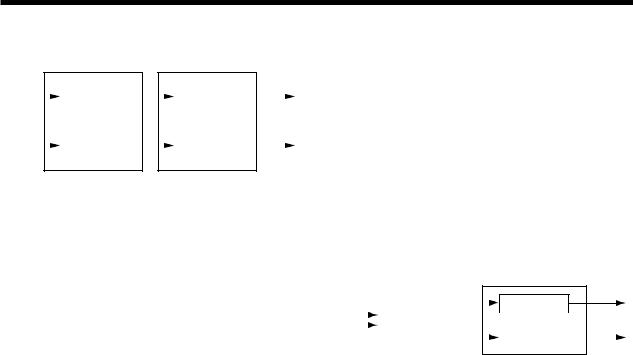
Chapter 1 Trying out the expanded functions
● Hum Canceler
This removes unwanted hum (electrical “buzz” or “drone”).
Input A |
|
|
|
Noise |
Output A |
||
|
|
Hum Canceler |
|
|
|
|
|
|
|
|
|
Suppressor |
|
|
|
|
|
|
|
|
|
|
|
|
|
|
|
|
|
|
|
|
|
|
|
|
|
|
|
|
|
Hum Canceler |
|
|
Noise |
|
|
Input B |
|
|
Suppressor |
Output B |
|||
|
|
|
|||||
|
|
|
|
||||
HC (Hum canceller)
HumCancel |
Off, On |
Freq |
20.0–800.0 Hz |
Width |
10–40 % |
Depth |
0–100 |
Thresh |
0–100 |
RngL |
Unlimit, 20–2000 Hz |
RngH |
1.0–20.0 kHz, Unlimit |
HumCancel (Hum canceller)
Turn the hum canceller on/off. If this is turned off, the following items will not be displayed.
Freq (Frequency)
Hum will be removed at the specified frequency and at multiples of that frequency. Set it to match the frequency of your power supply.
Width
Specify the width of the filter which will remove the hum.
Depth
Specify the depth of the filter which will remove the hum.
Thresh (Threshold)
Adjust the level at which the hum canceller will begin to take effect. If the signal falls below the specified level, only the hum will be removed from the signal. With the maximum setting, hum will always be removed regardless of the level of the signal.
RngL (Range low)
Specify the lower limit of the frequency range in which the hum canceler will operate. With a setting of Unlimit, the limit will be the lowest frequency that the VS-880 is capable of playing back.
RngH (Range high)
Specify the upper limit of the frequency range in which the hum canceller will operate. With a setting of Unlimit, the limit will be the highest frequency that the VS-880 is capable of Playing back.
NS (Noise suppressor)
NoiseSup |
Off, On |
Thresh |
0–100 |
Release |
0–100 |
Thresh (Threshold)
Adjust the level at which the noise suppressor will begin to operate.
Release
Adjust the time from when the noise suppressor begins to operate to when the volume reaches 0.
● Vocal Canceller
When a stereo source is being input from CD or DAT etc., this cancels the sound which is located in the stereo center, such as the vocal or bass.
Output L
Input L |
|
|
|
|
Equalizer |
|
|
|
|
|
|
|
|||
|
|
Vocal Canceler |
|
|
|
|
|
Input R |
|
|
|
|
Equalizer |
|
|
|
|
|
|
|
|||
Output R
*Depending on the musical source, sounds that you do not wish to be canceled may be canceled as well. In particular if the musical source has heavy reverb or if the sound that you wish to delete is not located in the center, the vocal canceller may not produce the desired result.
VC (Vocal canceller)
VclCancel |
Off, On |
Balance |
0–100 |
RngL |
Unlimit, 20–2000 Hz |
RngH |
1.0–20.0 kHz, Unlimit |
VclCancel (Vocal canceller)
Turn the vocal canceller on/off. If this is turned off, the following items will not be displayed.
Balance
If the sound that you wish to cancel is not located in the center, find the point at which it is most effectively canceled.
RngL (Range low)
Specify the lower limit of the frequency range from which you wish to cancel a sound. Use this setting when you wish to decrease the volume of the vocal without affecting a lowfrequency instrument (such as bass) located in the center. With a setting of Unlimit, the lowest frequency which the VS-880 is capable of Playing back will be the lower limit.
RngH (Range high)
Specify the upper limit of the frequency range from which you wish to cancel a sound. Use this setting when you wish to decrease the volume of the vocal without affecting a high-frequency instrument located in the center. With a setting of Unlimit, the highest frequency which the VS-880 is capable of Playing back will be the upper limit.
28

Chapter 1 Trying out the expanded functions
EQ (Equalizer)
EQ |
Off, On |
LowType |
Shlv, Peak |
Low.G |
-12–12 dB |
Low.F |
20–2000 Hz |
Low.Q |
0.3–10 |
Mid.G |
-12–12 dB |
Mid.F |
200–8000 Hz |
Mid.Q |
0.3–10 |
HiType |
Shlv, Peak |
Hi.G |
-12–12 dB |
Hi.F |
1.4–20.0 kHz |
Hi.Q |
0.3–10 |
OutLevel |
0–100 |
EQ (Equalizer)
Turn the equalizer on/off. When this is off, the following items will not be displayed.
LowType
Select the type of the low range equalizer.
Shlv: Shelving type
Peak: Peaking type
Hi.F (High frequency)
Specify the center frequency of the high range equalizer.
Hi.Q (High Q)
Specify the width of the band centered on the high range equalizer center frequency in which the gain adjustment will occur. As this setting is raised, the width of the band affected will become narrower.
OutLevel (Output level)
Adjust the volume level of the sound that has passed through the equalizer.
● Vocoder 2
This is a 19 band vocoder. A clear sound that was not possible with conventional vocoders can be obtained.
Input an instrumental sound into the left channel, and a voice into the right channel.
*Vocoder 2 can be used only for EFFECT-1. Also, EFFECT- 2 will not be available for use.
Input L |
|
(Instrument) |
Output L |
|
Low.G (Low gain)
Specify the gain (amount of boost/cut) for the low range equalizer.
Low.F (Low frequency)
Specify the center frequency of the low range equalizer.
Low.Q (Low Q)
Specify the width of the band centered on the low range equalizer center frequency in which the gain adjustment will occur. As this setting is raised, the width of the band affected will become narrower.
Mid.G (Middle gain)
Specify the gain (amount of boost/cut) for the mid range equalizer.
Mid.F (Middle frequency)
Specify the center frequency of the mid range equalizer.
Mid.Q (Middle Q)
Specify the width of the band centered on the mid range equalizer center frequency in which the gain adjustment will occur. As this setting is raised, the width of the band affected will become narrower.
HiType (High type)
Select the type of the high range equalizer.
Shelv: Shelving type
Peak: Peaking type
Hi.G (High gain)
Specify the gain (amount of boost/cut) for the high range equalizer.
|
|
|
Vocoder |
|
|
|
|
+ |
|
|
Stereo Chorus |
|
|
||
|
|
|
|
+ |
|
|
|
|
|
||||||
|
|
|
|
|
|
|
|
|
|
|
|||||
|
|
|
|
|
|
|
|
|
|
|
|
|
|
||
Input R(Mic) |
|
|
|
|
|
|
|
|
|
|
Output R |
||||
|
|
|
|
|
|
|
|
|
|
||||||
|
|
|
|
|
|
|
|
|
|
|
|
|
|
|
|
|
|
|
Noise |
|
|
|
|
|
|
|
|
|
|
|
|
|
|
|
Suppressor |
|
|
|
|
|
|
|
|
|
|
|
|
|
|
|
|
|
|
|
|
|
|
|
|
|
|
|
|
VOC (Vocoder)
Env |
Sharp, Soft, Long |
Pan |
Mono, Stereo, L R, R L |
Hold |
Off, MIDI |
MicSens |
0–100 |
SynInLev |
0–100 |
V.Char1-19 |
0–100 |
MHPF |
Thru, 1.0–20.0 kHz |
MHPFPan |
L63–R63 |
MicMix |
0–100 |
NSThresh |
0–100 |
Env (Envelope)
Sharp: The human voice will be emphasized.
Soft: The instrumental sound will be emphasized. Long: A vintage sound with long decay will be pro-
duced.
Pan
Select Mono, Stereo, L R or R L. With a setting of Mono, the components of each frequency band will be located in the center. With a setting of Stereo, the odd-numbered frequency bands will be located at the left, and the even-num- bered components at the right. With a setting of L R, the low frequency bands will be located increasingly toward the left, and the high frequency bands will be located increasingly toward the right. With a setting of R L, the low frequency bands will be located increasingly toward the right, and the high frequency bands will be located increasingly toward the left.
Chapter 1
29
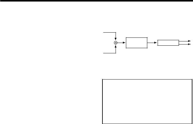
Chapter 1 Trying out the expanded functions
Hold
This turns the Hold function on/off. When MIDI is selected, the MIDI control change message Hold will be received. The MIDI channel is fixed at 1. If you turn Hold on while a voice is being input into the mic, the instrument will sound with the vocal formats that are fixed at that time.
MicSens (Mic sensitivity)
Adjust the input sensitivity of the mic.
SynInLev (Synthesizer in level)
Adjust the input level of the instrument.
V.Char1–19 (Voice character)
Adjust the volume of each frequency band. This setting adjusts the tone of the vocoder.
As the value is increased, the frequency will rise.
MHPF (Mic HPF)
When mic mix is used, this adjusts the frequency at which the high pass filter (HPF) will begin to affect the mic audio. Higher values for this setting will allow you to mix only the consonants. With a setting of Thru, the HPF will not be applied.
MHPFPan (Mic HPF pan)
Adjust the panning of the mic audio.
MicMix (Mic mix)
Adjust the amount of the mic audio (R channel input) which has passed through the mic HPF that will be added to the output of the vocoder.
NSThresh (Noise suppressor threshold)
Adjust the level at which the noise suppressor applied to the instrumental input (R channel input) will begin to function.
CHO (Chorus)
Chorus |
Off, On |
Rate |
0.1–10.0 Hz |
Depth |
0–100 |
PreDLY |
0–50.0 msec |
MixBal |
0–100 |
Chorus
Turn the chorus on/off. If this is turned off, the following items will not be displayed.
Rate
Adjust the modulation rate of the chorus.
Depth
Adjust the modulation depth of the chorus.
PreDLY (Pre delay)
Adjust the time from when the direct sound is output until the chorus sound is output.
MixBal (Mix balance)
Adjust the balance between the chorus volume and the direct volume.
● Voice Transformer
This independently controls the basic pitch and the formants, allowing a variety of voice characters to be created.
Input L
Output L
Voice
Reverb
Transformer
Output R
Input R
*Voice Transformer can be used only in EFFECT-1. Also, EFFECT-2 will not be available for use.
< Hints for voice input >
Input only a single voice. If several voices are input, the VS-880 will not operate properly.
Be sure that sound from a speaker does not enter the microphone you are using. This will have the same effect as if several voices were input to the unit (i.e. the VS-880 will not function properly).
We recommend that you use a unidirectional microphone; speak or sing as close to the microphone as possible.
VT (Voice transformer)
VoiceTrns |
Off, On |
Robot |
Off, On |
C.Pitch |
-12–36 |
F.Pitch |
-100–100 |
C.Formant |
-12–12 |
F.Formant |
-100–100 |
MixBal |
0–100 |
VoiceTrns (Voice transformer)
Turn the voice transformer on/off. If this is off, the following items will not be displayed.
Robot
Turn the robot function on/off. When this is on, the audio will be output at a fixed pitch regardless of the pitch that is input, producing a voice character without inflection.
C.Pitch (Coarse pitch)
Adjust the pitch of the voice character in semitone steps. This can be adjusted over a range of 1 octave down to three octaves up.
F.Pitch (Fine pitch)
Make fine adjustments to the pitch of the voice character.
C.Formant (Coarse formant)
Adjust the formant of the voice character in semitone steps.
F.Formant (Fine formant)
Make fine adjustments to the formant of the voice character.
30
 Loading...