


HSB2 PLUS

hsb
2
PLUS Series
LCD Display
Owner’s
Handbook
Document number: 81186_3
Date: September 2002


Preface iii
hsb
PLUS Series LCD Display Owner’s
Handbook
September 2002
INTENDED USE
Thedisplayunitsdetailedin this handbook may form part ofnavigational
radarsystemsintendedfor light marine use. These displaysandradar
systems are only an aid to navigation.
SAFETY NOTICES
Thisradarequipmentmust be installed and operated in accordance with the
instructionscontainedinthismanual.Failuretodosocan result in personal
injuryand/ornavigationalinaccuracies.In particular:
1.HIGH VOLTAGE.TheLCD display unit and scanner unitcontain
highvoltages.Adjustmentsrequirespecializedservice proceduresand
toolsonlyavailabletoqualifiedservicetechnicians–therearenouser
serviceablepartsoradjustments.Theoperatorshouldnever removethe
displayunitcoveror attempt to service the equipment.
2
2.ELECTROMAGNETIC ENERGY. Theradar scannertransmits
electromagneticenergy. It is important that the radar is turned off whenever
personnelarerequiredtocomecloseto the scanner to perform work on the
scannerassemblyorassociatedequipment.
Itisrecommendedthatthe radar scanner is mountedoutofrangeofpersonnel
(aboveheadheight).
Avoid lookingdirectlyattheantennaasyoureyesarethemostsensitivepartof
thebodyto electromagneticenergy.
Whenproperlyinstalled andoperated,theuse of thisradarwillconformto the
requirementsofANSI/IEEEC95.1-1992StandardforSafetyLevelswith
RespecttoHumanExposuretoRadioFrequencyElectromagneticFields,3Hz
to300GHzandNRPB, Board StatementonRestrictionson HumanExposure
toStati candTimeVarying ElectromagneticFieldsandRadiation.DocNRPB,
N0.5 (1993).
4.NAVIGATIONAID.Thisunit isonlyanaidtonavigation.Itsaccuracycan
beaffectedbymanyfactors,includingequipmentfailureordefects,
environmentalconditions,andimproperhandlingoruse.Itisthe user’s
responsibilitytoexercisecommonprudenceandnavigationaljudgements.
Thisradarunitshouldnotberelieduponasasubstitut efor such prudence and
judgement.

iv hsb
Raymarineproductsaresupportedbya network of Authorized Service
Representatives.Forinformationonourproductsandservices,contacteither
ofthe following:
UNITEDSTATES RaymarineInc.
22 Cotton Road, Unit D
Nashua,NH 03063-4219
Telephone: +1603 881 5200
+1800 539 5539
Fax: +1603 864 4756
EUROPE RaymarineLimited
AnchoragePark
Portsmouth
Hampshire PO3 5TD
England
Telephone: +44(0) 23 9269 3611
Fax: +44(0)23 9269 4642
Copyright© Raymarine Ltd.2002
2
PLUS Series LCD Display
Thetechnicalandgraphicalinformationcontainedinthishandbook,to the
bestofourknowledge,wascorrectasitwenttopress.However,ourpolicyof
continuousimprovementandupdatingmay change product specifications
withoutpriornotice. As aresult,unavoidabledifferencesbetweentheproduct
andhandbookmay occur from time to time, for whichliabilitycannotbe
acceptedbyRaymarine.
Raymarineisa registeredtrademarkofRaymarineLimited.
SeaTalk is aregisteredtrademarkofRaymarineLimited.
2
hsb
isa trademarkof RaymarineLimited.
Pathfinder Plus is a trademark of Raymarine Limited.
ThisproductcontainstechnologyprovidedunderlicensebyAcornGroupplc.
ThecopyrightofthisintellectualpropertyisacknowledgedbyRaymarine
Ltd.,asareAcorn’strademarksand patents. Acorn’sworldwideweb address
is http://www.acorn.com.

Preface v
Preface
Thishandbookdescribestheradarandchart aspectsof the following hsb
(PLUS)seriesdisplaysystemsfromRaymarine:
System Display Scanner Chartplotter
Pathfinder Radar RL70 PLUS Yes No
Raychart Chartplotter RC520PLUS No Yes
Combined Pathfinder Radar/Chartplotter RL70RC PLUS Yes Yes
Thishandbookalsodescribestheuse of multi-displaysystems.
Note:Radar systems are supplied with an appropriate Raymarine scanner
unitandinter-connectingcable.Detailsforinstallingthescanneraredescribedinthe PathfinderRadar Scanner Owner’s Handbook.
TheRaychart(RC)display units include a cartridge holder assembly which
containstwoslotsforC-MAP NT chart cards.
Thishandbookcontainsveryimportantinformationontheinstallationand
operationofyournew equipment.In order to obtain the best results in
operationandperformance,pleasereadthishandbookthoroughly.
Raymarine’s TechnicalServicesrepresentativesor yourlocaldealerwillbe
availabletoanswerany questionsyou may have.
2
Warranty
To registeryourdisplayunitownership,pleasetakeafew minutes to fill out
thewarrantyregistrationcardfoundattheendof this handbook. It is very
importantthatyoucompletetheownerinformationandreturnthecardto the
factoryinordertoreceivefullwarrantybenefits.
EMC Conformance
AllRaymarineequipmentandaccessoriesaredesignedtothebestindustry
standardsforusein the recreationalmarineenvironment.
Thedesignand manufacture of Raymarine equipment and accessories
conformtotheappropriateElectromagneticCompatibil ity(EMC) standards,
butcorrectinstallationisrequiredtoensurethatperformanceisnot
compromised.

vi hsb
2
PLUS Series LCD Display
Contents
Preface ............................................................................................... v
Warranty ...........................................................................................v
EMC Conformance ...........................................................................v
Chapter 1: Overview ..........................................................................................1.1
How to Use This Handbook .......................................................... 1.1
1.1 General .......................................................................................... 1.4
Introductiontohsb2 Systems ........................................................ 1.4
PLUS Display Units ..................................................................... 1.5
OperatingModes .......................................................................... 1.6
Headingand Position Data ........................................................... 1.9
1.2 The Pathfinder Radar PLUS Display .......................................... 1.10
PathfinderRadarPLUS Display Options ................................... 1.10
Radar Functions ......................................................................... 1.12
1.3 The Chartplotter Display ..................................................... .......1.13
ChartplotterDisplayOptions ...................................................... 1.14
ChartplotterFunctions ................................................................ 1.15
1.4 Operating Controls .....................................................................1.16
TrackpadandCursor ................................................................... 1.16
DedicatedKeys ........................................................................... 1.18
SoftKeys ..................................................................................... 1.19
Pop-Up Menus ............................................................................ 1.19
DatabaseLists ............................................................................. 1.20
Chapter 2: Getting Started & Adjusting the Display ....................................2.1
2.1 Introduction ..................................................................................2.1
ConventionsUsed ......................................................................... 2.1
Simulator ...................................................................................... 2.1
2.2 Switching the Display Onand Off ................................................ 2.2
SimulatorMode ............................................................................ 2.5
Changingthe Lighting & Contrast ................................................ 2.6
2.3 Controlling the Display ................................................................. 2.7
SelectingtheMode of Operation .................................................. 2.7
CustomizingtheScreen PresentationOptions ............................ 2.13

Preface vii
2.4 Radar Display Control Functions ............................................... 2.16
Using the Zoom Function ........................................................... 2.16
OffsettingtheCenter ................................................................... 2.17
Hidingthe Ship’sHeadingMarker(SHM) ................................. 2.18
2.5 Chart Display Control Functions ................................................ 2.19
MovingAround the Chart ........................................................... 2.19
2.6 TypicalChartScenarios .............................................................. 2.23
Placeand Goto a Waypoint ......................................................... 2.24
Makeand Follow a Route ........................................................... 2.26
ReviewYour Passage Plan .......................................................... 2.28
ReviewYour Passage Plan .......................................................... 2.29
DisplayingtheRadarand SynchronizingRadar & Chart ........... 2.30
Chapter 3: Standard Radar Operations ..........................................................3.1
3.1 Introduction ..................................................................................3.1
3.2 Range Control ............................................................................... 3.2
Changingthe Range ...................................................................... 3.3
DeterminingActualRadar Range ................................................. 3.3
3.3 Interpreting and Adjusting the RadarPicture ............................... 3.4
IdentifyingFalseEchoReturns .................................................... 3.5
AdjustingGain,Sea Clutter,RainClutterandTune ..................... 3.7
Changingthe Targets Display ......................................................3.11
3.4 Measuring Range and BearingUsing VRM/EBLs .................... 3.13
MeasuringRange and Bearing to TargetfromVessel ................. 3.14
MeasuringRange and Bearing Between Targets(FLOAT)........ 3.16
ControllingVRM/EBL Data Boxes ...........................................3.18
3.5 Setting Guard Zones andAlarms ................................................ 3.19
Placinga Guard Zone .................................................................. 3.20
Moving,Reshaping or Deleting a Guard Zone ........................... 3.21
ControllingGuardZone Alarms ................................................. 3.21
3.6 MARPA ............................................................................... .......3.23
IntroductiontoMARPA ............................................................. 3.23
Using MARP A............................................................................ 3.25

viii hsb
2
PLUS Series LCD Display
Chapter 4: Integrated Radar Operations ........................................................4.1
4.1 Introduction ..................................................................................4.1
4.2 Changing the HeadingMode ........................................................ 4.2
TrueandRelativeMotion ............................................................. 4.2
4.3 Using Marks .................................................................................. 4.4
4.4 Man Overboard(MOB) ................................................................ 4.5
4.5 Cursor Echo .................................................................................. 4.6
Chapter 5: Standard Chart Operations ...........................................................5.1
5.1 Introduction ..................................................................................5.1
5.2 Using Chart Cards ......................................................................... 5.2
Insertinga Chart Card ...................................................................5.2
Removing a Chart Card ................................................................ 5.3
DisplayingtheChart Data ............................................................. 5.3
DisplayingChartObjectand Source Information ........................ 5.4
5.3 WorkingwithWaypoints .............................................................. 5.8
Introduction .................................................................................. 5.8
Placinga Wayp oint ....................................................................... 5.9
SelectingaW aypoint .................................................................. 5.12
Waypoint DataDisplay ............................................................... 5.12
Editingthe WaypointDetails ...................................................... 5.13
Erasinga Waypo int ..................................................................... 5.14
Movinga Waypoint .................................................................... 5.14
Using the ST60 or ST80 NavigatorKeypad ............................... 5.15
5.4 WorkingwithRoutes ..................................................................5.18
Creatinga New Route .................................................................5.19
Savingthe Current Route ............................................................ 5.22
ClearingtheCurrent Route .........................................................5.23
Retrievea Route From the Database........................................... 5.23
DisplayingRouteInformation .................................................... 5.24
Usingthe Route List to EraseandName a Route ....................... 5.26
Editing a Route ...........................................................................5.27
5.5 Following Routes and Goingto Points ....................................... 5.29
Followa Route ............................................................................ 5.29
Target Point Arrival .................................................................... 5.31

Preface ix
OtherFollow Route Options ....................................................... 5.31
Going ToanIndividualTarget Point ........................................... 5.32
StopFollowor Stop Goto ............................................................ 5.33
5.6 TransferringWaypoints and Routes ...........................................5.34
5.7 Using Tracks ...............................................................................5.38
SettingUp a Track ...................................................................... 5.39
ClearingtheCurrent Track ......................................................... 5.40
ManagingTracks ........................................................................5.40
SmartRoute ................................................................................. 5.42
Chapter 6: Further Chart Operations ..............................................................6.1
6.1 Introduction ..................................................................................6.1
6.2 Measuring Distances Using the VRM/EBLKey .......................... 6.2
6.3 Alarms and Timers........................................................................ 6.4
Alarm Reporting ........................................................................... 6.4
SettingAlarms and Timers ........................................................... 6.5
6.4 Man Overboard(MOB) ................................................................ 6.6
6.5 Cursor Echo .................................................................................. 6.7
6.6 GPS Setup ..................................................................................... 6.8
6.7 Data Log Mode ...........................................................................6.10
Chapter 7: Setting Up the System Defaults ...................................................7.1
7.1 Introduction ..................................................................................7.1
7.2 Changing the SetUp Parameters .................................................. 7.2
7.3 System Set Up Parameters ............................................................ 7.4
Data Boxes .................................................................................... 7.6
BearingMode ............................................................................... 7.6
CursorReference .......................................................................... 7.6
CursorReadout .............................................................................7.6
Day/Night ..................................................................................... 7.7
Help............................................................................................... 7.7
SoftKeys ....................................................................................... 7.7
KeyBeep ...................................................................................... 7.7
MOB Data ..................................................................................... 7.7
AutopilotPop Up .......................................................................... 7.7

x hsb
MenuTimeoutPeriod ...................................................................7.7
Units .............................................................................................. 7.8
Variation Source ........................................................................... 7.8
BridgeNMEA Heading ................................................................7.9
NMEA Out Set Up ........................................................................ 7.9
CursorEcho .................................................................................. 7.9
Date and TimeSettings ...............................................................7.10
GPS SOG/COG Filter ................................................................. 7.10
CompassSet Up .......................................................................... 7.10
Language .................................................................................... 7.10
Simulator .....................................................................................7.11
7.4 Radar Set UpParameters ............................................................ 7.12
EBL Display ............................................................................... 7.12
TimedTrans missi onOption .......................................................7.13
MarksOptions ............................................................................ 7.13
CustomScale .............................................................................. 7.13
BearingAlignment ..................................................................... 7.14
AntennaSize ............................................................................... 7.14
Sendon HSB ............................................................................... 7.14
2
PLUS Series LCD Display
7.5 MARPASetUpParameters ........................................................ 7.15
7.6 Advanced Settings ...................................................................... 7.16
DisplayTiming ...........................................................................7.16
STC Preset .................................................................................. 7.17
TunePreset..................................................................................7.17
7.7 Chart Set UpParameters ............................................................. 7.18
CustomizeChart ......................................................................... 7.18
PlotterMode ............................................................................... 7.19
ChartOrientation ........................................................................7.19
ObjectInformation ..................................................................... 7.20
Waypoint Options ....................................................................... 7.20
Vectors ........................................................................................ 7.20
Radar/ChartSynch ...................................................................... 7.20
DatumSelection ......................................................................... 7.20
PositionOffset ............................................................................ 7.21

Preface xi
Chapter 8: Installation ......................................................................................8.1
8.1 Introduction ..................................................................................8.1
Planningthe Installation ............................................................... 8.2
EMC Installation Guidelines ........................................................ 8.2
8.2 Unpacking and Inspecting theComponents ................................. 8.4
8.3 Selecting the Display Unit Location .............................................8.5
8.4 Cable Runs .................................................................................... 8.7
PowerCable .................................................................................. 8.7
Inter-UnitScannerCable .............................................................. 8.8
2
hsb
Cable ..................................................................................... 8.8
8.5 Mounting the DisplayUnit ........................................................... 8.9
8.6 System Connections ....................................................................8.11
DisplayUnit Connection ............................................................ 8.12
8.7 Radar System TestsandInstallationAlignment ......................... 8.15
SystemCheck ............................................................................. 8.15
SwitchOn and Initial Setup ........................................................8.15
RadarSystem Checks and Adjustments ..................................... 8.16
EMC Conformance ..................................................................... 8.20
8.8 Integrated Systems ...................................................................... 8.20
2
hsb
™(High Speed Bus) Multiple Display Systems .................. 8.20
SeaTalk® andNMEA In ............................................................. 8.23
Usingthe SeaTalkAuxiliaryJunctionBox................................. 8.28
Data Output .................................................................................8.29
Data Conversion ......................................................................... 8.30
8.9 Integrated System Checks .......................................................... 8.31
ChartDisplay- RL70 PLUS, RL70RC PLUS, RC520 PLUS .... 8.31
ReceivedData ............................................................................. 8.31
TransmittedData ........................................................................ 8.31
Chapter 9: Maintenance and Problem Solving ..............................................9.1
9.1 Maintenance .................................................................................9.1
RoutineChecks ............................................................................. 9.1
EMC Servicing and Safety Guidelines ......................................... 9.1

xii hsb
2
PLUS Series LCD Display
9.2 Resetting the System ..................................................................... 9.2
9.3 Problem Solving ........................................................................... 9.3
Technical Support: ........................................................................ 9.3
How to Contact Raymarine (US) .................................................. 9.4
How to Contact Raymarine (Europe) ...........................................9.5
Worldwide Support ....................................................................... 9.5
Appendix A: Specification ...................................................................................A.1
2
hsb
Series7"LCD Displays .........................................................A.1
Appendix B: Using the Auxiliary Junction Box ................................................. B.1
Raystar112,105,Apelco182and 182XT ....................................B.2
AutohelmGPS, Z260 and Z273 ...................................................B.3
Raystar112LP(SeaTalk version) .................................................B.4
Raystar114CombinedGPSandDifferentialBeaconReceiver ...B.5
Raystar120 WAAS Satellite Differential Receiver ......................B.6
Appendix C: C-MAP Chart Card Features .......................................................... C.1
Appendix D: SeaTalk and NMEA Data Received and Transmitted ................ D.1
Appendix E: Connecting a Raymarine Heading Sensor ...................................E.1
G-SeriesCourseComputer ...........................................................E.1
Appendix F: Abbreviations ..................................................................................F.1
Index.................................................................................................xiii

Chapter 1: Overview 1-1
Chapter 1: Overview
How to Use This Handbook
Thishandbookdescr ibesthefollowinghsb2(PLUS)seriesdisplays andmultidisplaysystems:
RL70PLUS Pathfinder Radar,7"LCD Display
RL70RCPLUS Pathfinder Radar & Chartplotter,7"LCDDisplay
RC520PLUS Chartplotter,7"LCDDisplay
Ifyouare installingthe displaysystem yourself,youshouldread Chapter 8
beforeyoustarttheinstallation.Thischapteralsoprovidesinformationthat
willbeuseful if you are connecting your
equipment.
2
hsb
Foranoverviewof
(PLUS)displaysystems ,thedisplayunitcontrols and
the radar/chartplotter system, read Chapter 1. Chapter 2 will help you start
usingyoursystem.
FordetailedinformationonradaroperationsrefertoChapter3:Standard
RadarOperationsandChapter 4:IntegratedRadarOperations.
2
hsb
series system to other
How to Use This
How to Use This
Handbook
Handbook
Forchartplotteroperatingdetails,refertoChapter 5 andChapter 6.
To changethesystemsetup defaults, read Chapter 7.
Detailsforinstallingaradarscannerareprovidedinthe Pathfinder Radar
ScannerOwner’s Handbook suppliedwithyourscanner.
Note:Many illustrationsinthishandbookshowexamplescreens.The screen
youseeon your display depends on your system configuration and set up options,soitmay differ from the illustration.
Thishandbookisorganizedasfollows:
2
hsb
Chapter 1providesanoverviewofan
featuresandfunctionsofthe
2
hsb
PLUSseriesLCD Display.Thischapteralso
multi-display system and the
providesanoverviewofthe controls.You should read this chapter to
familiarizeyourselfwiththesystem.
Chapter 2explainshow to start using the display and describes how to use
someofthebasicradarandchart functions.Chapter2alsoprovidesoperating
guidelinesfortypicalchartplotterscenarios;theseguidelinesintroduceyou to
manyof the chartplotterfunctions.
Chapter 3providesdetailedoperatinginformationforthemainradar
functions-adjustingtheradarpicture;measuringdistancesandbearings;
settingguardzonesandalarms;usingMARPA fortargettracking.

1-2 hsb
2
PLUS Series LCD Display
How to Use This
How to Use This
Handbook
Handbook
Chapter 4providesdetailedoperatinginformationforintegratedradarsystem
functions,includingusingmarks,manoverboardandcursorecho.
Chapter 5providesdetailedoperatinginformationforthestandard
chartplotterfunctions- usingchartcards,plottingwaypointsandroutes,
followingroutesandshowingtracks.
Chapter 6providesdetailedoperatinginformationforfurtherchartfunctions,
includingmeasuringdistances,manoverboardandcursorecho.Itincludes
instructionsforsettingupadifferentialGPS.
Chapter 7providesinstructionsforsettingupyoursystemto suit your
preferences.Youshouldreadthischaptertodeterminehowtosetuptheradar
andchartplottersystemdefaults.
Chapter 8providesplanningconsiderationsanddetailedinstructionsfor
installingthedisplayunit(s).Itshouldbereferredtowhenyouare ready to
installthesystem.Detailstoconnectthedisplaytoother equipment are also
provided.To installacompleteradarsystem,you will also need to read the
Owner’sHandbooksuppliedwiththescanner.
Chapter 9providesinformationonuser maintenance,and what to do if you
experienceproblems.
TheAppendicesprovideadditionalinformationthatyoumayfinduseful:
Appendix Aliststhetechnicalspecificationsfortheradarandchartplotter.
Appendix BprovidesdetailsonconnectingthedisplayunittospecificGPS
systems.
Appendix Cdefinesthechartfeaturesshown on the chart display.
Appendix Ddefines the SeaTalk and NMEA data that is transferred on
integratedsystems.
Appendix EprovidesdetailsonconnectingaRaymarineheadingsensorfor
MARPA.
Appendix Fprovidesalistof abbreviations.
AnIndexand warranty information are included at the end of thehandbook.
Asummaryof the radar and chartplotter controls are provided on the Quick
ReferenceCardssuppliedwithyoursystem.

Chapter 1: Overview 1-3
Terminology
Thefollowingterminologyisusedto describe radar and chartplottersystems:
Master A unit capable of sourcing specificdata such as
fishfinder ,chart or radar data.
Repeater A unit capable of displaying data, such as radar,from
2
hsb
.
FishfinderDisplayUnitprovidingFishfinder Master,ChartRepeaterand
RadarRepeaterfunctionality.
RadarDisplay UnitprovidingRadar Master, FishfinderRepeater
andChart Repeaterfunctionality.
ChartDisplay UnitprovidingChartMaster,Fishfinder Repeater and
RadarRepeaterfunctionality.
CombinedDisplayUnitprovidingbothRadarandChartMaster or Fishfinder
andChart Masterfunctionality.
2
hsb
IntegratedSystemAdditionalinstrumentsareconnectedviathe
SeatalkorNMEA interfaces.
,
How to Use This
How to Use This
Handbook
Handbook
2
hsb
™ HighSpeed Bus - links compatible display units.
ItsupersedesHSB and allows multipledisplaysystems.
Forfulldisplayand control between
units,theunitsmust be connected via
hsb
hsb
2
series display
2
andSeaTa lk.

1-4 hsb
1.1 General
General
General
Thehsb2(PLUS)seriesPathfinderRadaror PathfinderRadar/Chartplotter
comprisesthe7"LCD display unit, scanner unit and associated cables. The
RC520PLUS Chartplotter cannot be connected to the scanner unit.
Display Unit
Thehsb2(PLUS)seriesdisplay unit is waterproof to CFR46 and canbe
installedeitheraboveorbelowdeck.
Theunitincludes:
• 7" LCD PLUS display
• Trackpad
• Elevendedicated(labeled)controlkeys
• Foursoftkeys(unlabeled)whose functionalitychanges
• ThePathfinderChartplottererandcombinedPathfinderRadar/Chartplot-
ter include two slots for the C-MAP NT
®
chartcards
2
PLUS Series LCD Display
Thedisplayandkeys can be illuminated for night-time use.
Scanner
Thehsb2seriesPathfinderRadarissuppliedwithascanner unit which
illuminatestargetswithmicrowaveenergyandthencollectsthereturnsfrom
thosetargets.Thescannerincludesasensitivelow-noisefrontendreceiver,
and a variety of clutter attenuation controls to maintain target resolution.
Thescannerisadjusted andoperatedfromthedisplayunit, sothesedetailsare
providedinthisHandbook.Itcan be switched between transmit and stand-by
modes.Italso hasapower-savingtimedtransmitmodewhich pausesbetween
burstsoftransmissions.
InstallationofthescannerisdescribedseparatelyintheScannerOwner’s
Handbook.
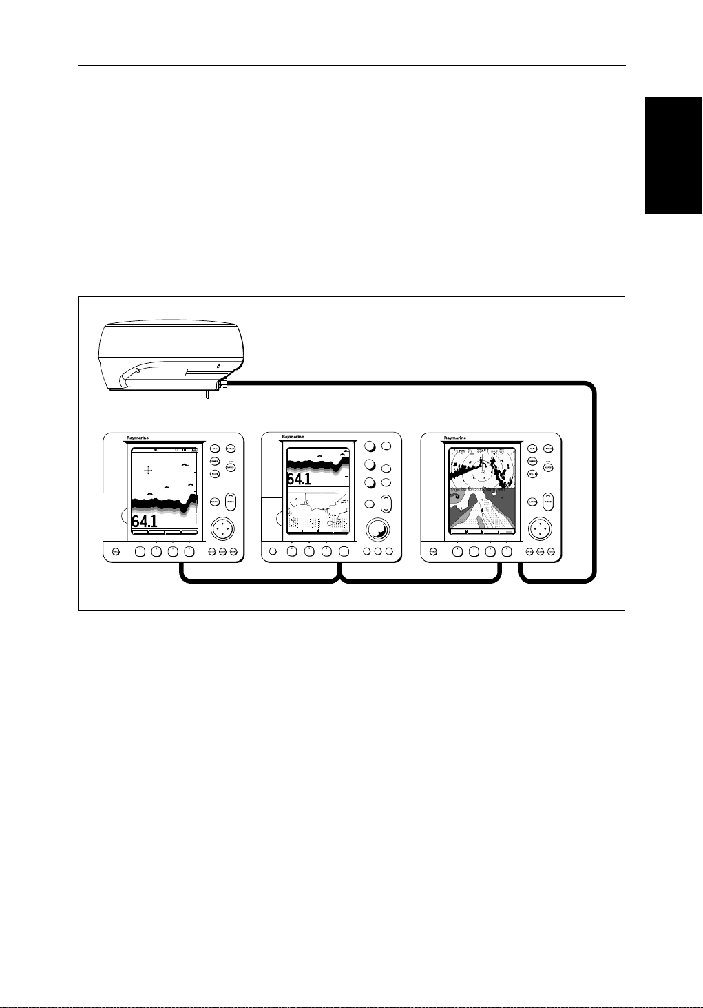
Introduction to hsb
Itispossibleto connect up to ten hsb2(PLUS)seriesLCD or CRTdisplays
(dependentoncablelengths)andascanner unit to provide an integrated
system.Thesystemmay include existingHSB display units that have been
suitablyupgraded-contactyourauthorizedRaymarine dealer for upgrade kit
details.
2
Systems
The
2
hsb
(HighSpeedBus) connectionenablestransferofdata between
compatibleunits.Forexample,radardataistransferredfromtheradar(the
masterdisplay)viathe
anyother
2
hsb
seriesLCDorCRTdisplay(therepeaterdisplay).
2
hsb
connectionandcanbedisplayedandcontrolledon
Chapter 1: Overview 1-5
Inparticular ,you canconnectyourRadarto a remote Chartplotter(or
Fishfinder/Chartplotter)to provide similar functionalityto the combined
Radar/Chartplotter(or Fishfinder/Chartplotter).However,youshouldbe
awarethatifyouchange,say,radarrangeononedisplay, itaffectsalldisplays
showingradar(orradar/chartoverlayoncolordisplays).
The
2
hsb
systemcanincludeseveral chartplotterdisplays,each with twochart
cartridgeslots.Eachdisplaycanaccesstwolocalandup to six remote chart
cartridges.Chartscanbecontr olledindependent lyoneachdisplay,evenwhen
aremotechartcartridgeisbeingused.
Pathfinder Scanner
PLUS Display Units
PLUS Display Units
hsb2 Fishfinder Display
AUTO GCRZFH
SD
50kHz
0
8
25
38
45
52
ft
ZOOMFREQUENCY
BTM.LOCK A-SCOPE
50
75
100
Fishfinder, Chart, Radar transferred to all displays
Figure 1-1:
hsb
PLUS Display Units
Features
• Chartplotter–DisplayschartinformationfromtheC-MAP NT®chart
cards(C-Cards)
• Usespositiondatafrom GPS, DGPS, WAASorLoran-Ctechnology
• Displaysandtransfers
• Providesfullcontrolofdatafrom other
hsb2 Radar/Chart Display
AUTO G RZ
50kHz
0
200
ft
ZOOM MORE¬FREQUENCY CHRT SNR
POWER
2
Integrated System
2
hsb
,SeaTalkand NMEA data
GAIN
SEA
MULTI
ALARMS
ENTER CLEAR MENU
2
hsb
Radar Display
DISPLAY
MOB
MARKS
VRM/EBL
RANGE
GOTO MORE!ROUTE RDR CHRT
D5569-1
2
hsb
instruments
• Severalfull-screenoperating modes including: Radar,Chart, DataLogor
Sonar,ifappropriatedataisavailable.
• Viewradarand chart simultaneouslyin half-screenwindows.
• Half-screenwindowstodisplayadditionaldata:CourseDeviationIndica-
tor(CDI),Bearingand Distance Indicator(BDI),navigationdata.

1-6 hsb
2
PLUS Series LCD Display
Operating Modes
Operating Modes
• CursorechoacrossSeaTalk,andbetweenchartand radar windows
• Choiceoforientation:HeadUp, Course Up and North Up
• Thesystemcan be connected to an ST80 Navigatorkeypadforentryof
alpha-numericdata.
Set Up Options
Setup optionsallowyou to choose what is displayed, how it isdisplayed
(includinglanguageandunits),bearingmodeandhow the display operates
withother
hsb
fromotherequipment,e.g.speed,heading,depth,wind and tide information
ina set of user-selectabledataboxes.Forsystemswithan autopilot,whenthe
statusandlockedheadinginformationchangethenew data can be displayed.
DisplayoptionsareprovidedinSystemSetUp, describedin Chapter 7.
ScreenPresentationOptions,describedinChapter 2 allow you toswitchthe
cursoranddataboxesOn/Off.Thecursorbox and user-selecteddataboxes
canbe moved around the screen.
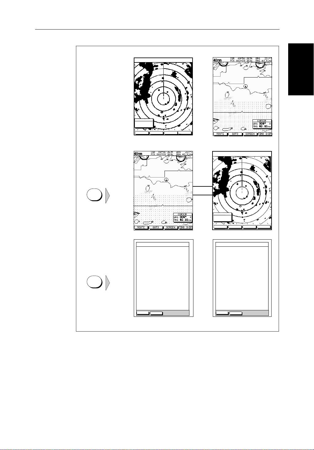
Operating Modes
Ona single hsb2unityou can view a full screen radar.You canalsoset
Win dowsOntosplitthedisplayintotwohalf-screenwindowsto show
supplementarydataor,on acombined displayunit, display radar and chart
simultaneously. The mainoperatingmode(radarorchart)isdisplayedin the
upperwindow;you choose what is displayed in the lowerwindow.
Thefollowingareavailable:
2
units.You can view the cursor position and avarietyofdata
Table 1-1:
Display Full-screen mode Half-screen Window Options
RL70 PLUS Radar CDI, BDI or Nav Data
RC520 PLUS Chart CDI, BDI or Nav Data
RL70RC PLUS
2
hsb
Single Display Operating Modes and Window Options
Data Log Windows not available
Radar Mode CDI, BDI, Chart or Nav Data
Chart Mode CDI, BDI, Radar or Nav Data
Data Log Mode Windows not available
Chapter 1: Overview 1-7
Radar Display Chartplotter Display
Operating Mode for
Stand Alone Units
RR
000°
0.220
1/2
HEAD UP
3nm
CURSOR
BRG
RNG nm
HDG MODE TARGETS SCREEN
IR
MARPA
Operating Modes
Operating Modes
Additional Modes for
Linked Units
(or combined
Radar/Chartplotter)
DISPLAY
TIME POSITION CMG DMG
DISPLAY
15:30
16:00
16:30
17:00
17:30
18:00
18:30
19:00
19:30
STOP LOG
50°21^890N
001°20^610W
50°18^010N
001°20^070W
50°21^850N
001°19^290W
50°18^500N
001°21^300W
50°20^990N
001°18^280W
50°19^660N
001°21^960W
50°19^730N
001°18^030W
50°20^930N
001°21^750W
50°18^550N
001°18^650W
CLEAR LOG
346°
180°H
012°H
206°H
043°H
245°H
093°H
302°H
145°H
H
Figure 1-2: Full Screen Operating Modes
6.86
7.23KM
7.23KM
6.67KM
5.74KM
5.00KM
4.63KM
5.00KM
5.74KM
KM
HSB
SeaTalk
RR
000°
0.220
1/2
50°21^890N
001°20^610W
50°18^010N
001°20^070W
50°21^850N
001°19^290W
50°18^500N
001°21^300W
50°20^990N
001°18^280W
50°19^660N
001°21^960W
50°19^730N
001°18^030W
50°20^930N
001°21^750W
50°18^550N
001°18^650W
CLEAR LOG
HEAD UP
346°
180°H
012°H
206°H
043°H
245°H
093°H
302°H
145°H
H
3nm
CURSOR
BRG
RNG nm
HDG MODE TARGETS SCREEN
TIME POSITION CMG DMG
15:30
16:00
16:30
17:00
17:30
18:00
18:30
19:00
19:30
STOP LOG
MARPA
6.86
7.23KM
7.23KM
6.67KM
5.74KM
5.00KM
4.63KM
5.00KM
5.74KM
IR
KM
D4285-1

1-8 hsb
2
PLUS Series LCD Display
Operating Modes
Operating Modes
Half-Screen Window Options
• Chartdisplay ,Radardisplay:Ifdataisavailableasafunctionof the
combineddisplayunititcanbe displayed full screen,as shown in
Figure 1-2, or in ahalf-screenwindow.
• CDI:This gives the Course Deviation Indicator graphicaldisplay,with
datarelatingtothetargetwaypoint.
• BDI:ThisgivestheBearingandDistanceIndicatorgraphicaldisplay,with
datarelatingtothetargetwaypoint.
• NavData:This shows ninedata boxes, providing navigationaldata in the
unitsspecifiedinyoursetup.Note that up to 6 ofthesedataboxesarealso
availableasauser-selectablegroup (seeSection 7.3).
You select the operating mode andwindowsusingthe DISPLAY key as
describedinChapter 2.
Multi-display systems
Ifyouhave several hsb2seriesRadarandChartplotterdisplaysconnected
operation is similar to acombined Pathfinder Radar/Chartplotter Unit: three
full-screenmodes–radar,chart and datalogare availableon all displays.
Inaddition,if you have an hsb
setany displaytofishfindermode;if thesystemincludesachartp lotter,similar
functionalitytoacombinedFishfinder/Chartplot teris availableon all
displays.
2
seriesFishfinderdisplayconnected,youcan
Onan
2
hsb
systemwithRadar,ChartandFishfinderavailable,thefollowing
informationcanbeshownon any display unit:
Table 1-2: Window Options for Integrated Systems
Full-screen mode Half-screen Window Options
Chart Mode, CDI, BDI, Nav Data, Fishfinder or Radar
Radar Mode CDI, BDI, Chart or Nav Data
Fishfinder Mode Depth/temp, Chart or CDI, BDI
Data Log Mode Windows not available
2
hsb
Fordetailson the fishfinder,refertothe
SeriesDisplayOwner’s
Handbooksuppliedwith your fishfinder.

Chapter 1: Overview 1-9
Heading and Position Data
Fullfunctionalityoftheradar/chartplotterisachievedwhenitispartof an
integratedsystemwithotherequipment(inadditiontoanother
connectedviaSeaTalk or NMEA 0183. Data from this equipment including
positionandheadingisshown on the display and is used in calculations.
DetailsonconnectingotherequipmentaregiveninChapter 8.
Providing Heading Data forMARPA
TheperformanceofMARPA is dependent on the quality of your heading
sensor. Itis importantthatboth the heading sensor and the radar scanner
(bearingalignment)arecorrectlycalibra ted.Refer to theappropriateheading
sensorandradarscannerhandbooksfor calibrationdetails.Thebetterthe
accuracyofyour heading data, the better the performance of MARPA.
Agyrocompassprovidesthebestperformancein allconditions.Alternatively
youcoulduse a fluxgate compass with rate gyro stabilization.
MARPA requires heading data to befrequentlyupdated(werecommend a
dataoutputrate ofgreaterthan8 Hz);headingdatamustthereforebeprovided
to the display on NMEA.
Inmultiple-displaysystems,headingmustbeconnected,viaNMEA, to each
displaythat will be used for MARPA.
hsb
2
unit)
Data
Data
Heading and Position
Heading and Position
We recommendthePathfinderSmartHeadingSystem(whichincludesthe
Gyro Plus 2 unit). Good results are also obtained with a Raymarine autopilot
systemincorporatinga150Gor400G Course Computer with internal rate
gyro.
OtherheadingsensorsconnectedonNMEA may provide satisfactory results
inreasonablesea states.However,in unsettledconditionsarategyrocompass
isadvisable.
ContactRaymarineCustomerServicesoryourauthorizedRaymarinedealer
foradditionalinformation.Forspecificconfigurationdetails with the
RaymarinecoursecomputerrefertoAppendix E. Ifyouareusing a suitable
third party heading sensor,refer to its documentation for installation and
calibrationdetails.

1-10 hsb
The Pathfinder Radar
The Pathfinder Radar
PLUS Display
PLUS Display
1.2 The Pathfinder Radar PLUS Display
2
PLUS Series LCD Display
Whenascanner is connected and the radar is in Transmitmode,theradar
pictureprovidesamap-likerepresentationoftheareainwhichthe radar is
operating.Typically,your ship’s position is at the centre of the display,andits
deadaheadbearing isindicatedbyaverticalheadingline,known as theShip’s
Heading Marker (SHM).
Theradarpicturecan be viewed with a variety of fixed orcustomisedrange
scales.Astatus bar at the top of the radarimagedisplaysrange,current
headingandmode indicatorsfor the various options you can set.
Anexample radar picture is shown on thenextpage,with example radar
returns(echoes)anddefaultPathfinderRadarinformation.TheStatusBaris
alsoillustrated.
Theradardisplaycan show additional information,dependingonyour
currentlyselectedoptions,setupselectionsandthedataavailablefromother
equipment.Theexampledisplaysonthefollowingpagesshowsomeof these
features.
Functionsareavailabletocontrolthedisplayasfollows:
• ZoomtheDisplay
• Offsetyourvesselfromthecentreofthe radar picture
OperationofthesefunctionsisdescribedinChapter 2.
Pathfinder Radar PLUS Display Options
In additionto the display set up options previously described,radarset up
optionsallowyouto customisethe radar image by selecting how radar marks
andElectronicBearingLine(EBL)dataare displayed.You can also specify
timedtransmitmodeand custom range scales.
TheScreenPresentationOptions,describedin Chapter 2allow you to switch
rangeringson/offandwaypointdisplayon/off.
Note:Whenyou turnthedisplayoff andonagain,the ScreenPresentationsettingsareretainedin memory.
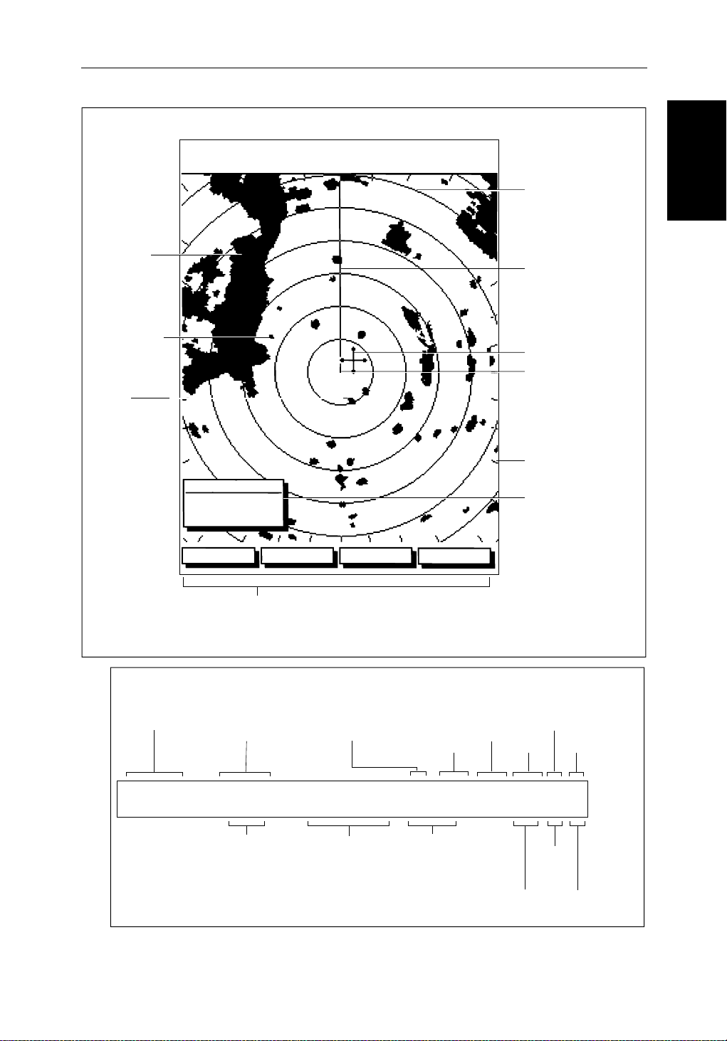
Chapter 1: Overview 1-11
Default Display
Targets:
Landmass
Channel buoy
Surface
vessel
RM RV3
H-UP
AUTO
T
MARPA
IR
045°
0.28
RR
1/2
126°T
R
3nm
CURSOR
BRG
RNG nm
HDG MODE TARGETS SCREEN
Default soft key labels
These can be turned off; press any soft key to re-display them.
Different labels are displayed when you press a key.
Status Bar
Range rings
The number and
spacing depend on
the current range, or
you can turn them off
Ship's Heading
Marker (SHM)
You can hide this
temporarily
Cursor position,
controlled by the
trackpad
Ship's position
You can move this
off-centre if required
Bearing scale,
each tick indicating
o
2
of azimuth
Cursor position box
Shows the current
cursor position as
either Range/Bearing
or Lat/Long. You can
move this box to your
preferred position
on the screen, or
turn it off.
D3600-5
Pathfinder Radar
Pathfinder Radar
PLUS Display Options
PLUS Display Options
Status Bar
Selected range,
in nautical miles
3nm
Figure 1-3: Radar Display Features
Range rings
(displayed if
rings are on)
RR
1/2
Range ring interval
Not displayed if
range rings are off
Motion Mode
Relative Motion
True Motion
126°T
Current heading
if data available, or
Course Over Ground.
Displayed in degrees
Magnetic or True
displayed when function on:
Target Vectors
True Vector or
Relative Vector
and vector length
RM RV3
H-UP
Heading mode
Normally Head Up (H-UP);
Course Up (C-UP) or
North Up (N-UP) can be
selected if heading data
available
Auto mode
Gain, Sea,
Tune
AUTO
GST
(Remote rain)
Mode Indicators
Target
Expansion
Wakes
WKS
FTCEXRCGZIR
FTC
Guard Zone
Alarms
Rain
Clutter
Interference
Rejection
D3993-3
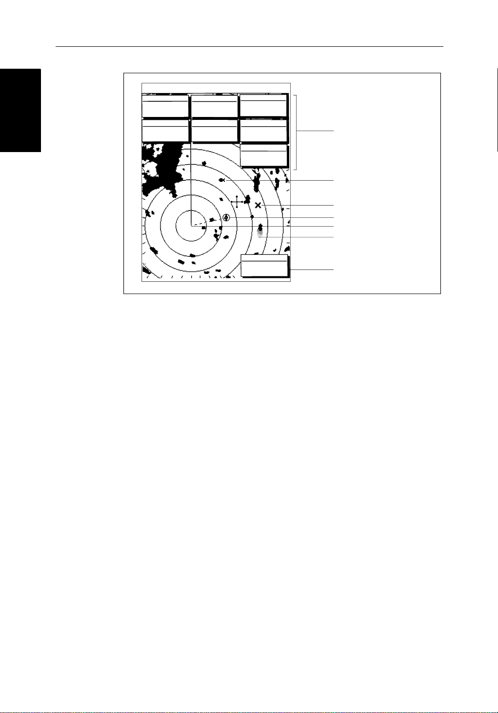
1-12 hsb
Radar Functions
Radar Functions
3nm
BRG
RNG
CURSOR
063°
1.65
COG
120@T
RR
1/2
R
001°12^09W
nm
126°T
POSITION
50°49^13N
SOG
6.3kts
AUTO
H-UP
GST
TIME
13:48:06
SPEED
5.7kts
DEPTH
FTC
FTC
EX
RC
IR
14.4m
WPT
T 1.20nm
203°
01h:30m
Figure 1-4: Typical Radar Picture
2
PLUS Series LCD Display
Data boxes, showing data
(if available) in the selected
units
Mark, symbol selected using
setup options
Mark, default symbol
Active waypoint - from Chartplotter
Offset centre
Long target wake (short,
medium or long wakes can
be selected)
Waypoint data box, showing
range, bearing and time to go
D3601-2
Radar Functions
Thehsb2(PLUS)seriesPathfinderRadarincludesthe followingfunctions:
• Choiceofrangescalesfrom
• Automaticandmanualcontrolof tuning,gain and sea clutter.
• TwoVariable Range Markers (VRMs) and ElectronicBearingLines
(EBLs),allowingtargetrangeandbearingmeasurements.
VRM/EBLs can be floated.
• Targetwakesandtargetexpansionmode.
• Twoguardzones with alarms.
• Addmarksto record important or dangerous locations.
• ManOverboard(MOB)to navigate back to a person or object.
•10TargetMARPA
OperationoftheseradarfunctionsisdescribedinChapter 3and Chapter 4.
1
/8nm to 72nm (dependent on scanner type).

Chapter 1: Overview 1-13
1.3 The Chartplotter Display
The PLUS series display can includes a Chartplotter.Thechartplotter
includesasmall-scaleworldmapanddetailednavigationinformationis
displayedwhenacartographicchartcardisinstalled.Thedetailsdisplayed
dependonthechartzoomlevelselected.Aplottermode is provided to enable
routeplottingandtrackingatlargescalesevenwhenachartcardis not
installed,orwhenthechart is zoomed beyond the available cartographic
detail.AtypicalchartplotterscreenisshowninFigure 1-5.
ThechartplotterusespositioninformationfromaGPS, DGPS, W AASor
Loran-Cinstrument.Oncethepositionfixhasbeenestablished,yourvessel’ s
position,ifonscreen,isshown as a boat shape pointing inthedirectionofthe
currentheading(orCOG if heading data is not available). If no heading or
COG data is available, the vessel is shown as a circle.
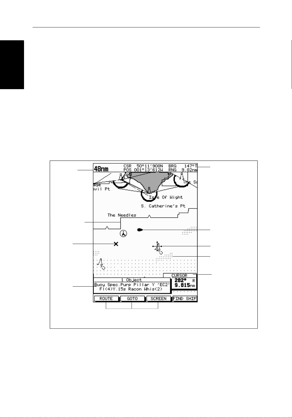
Thechartplotterscreenincludesastatusbarthatdisplayschartscale,with
eithercursorposition,rangeandbearingor,whenthecursorishomedto the
vessel(bypressingFIND SHIP),vesselposition,SpeedOver Ground (SOG),
CourseOver Ground (COG) and fix type (VESPOS, DIF FIX or SDFIX).
Thestatusbaralsoindicatesif radar/chartoverlayisswitchedon.
The Chartplotter
The Chartplotter
Display
Display
Anywaypointsyou have placed are displayed (unless you turned them off in
ChartSetUp as described in Chapter 7) and thecurrentrouteisshown.
Informationcanbeviewedon-screenby positioningthe cursor over a
waypoint,currentrouteorchartobject.Thechartplotterscreencanalsoshow
additionalinformation,dependingonyourcurrentlyselectedoptions,setup
selectionsanddataavailablefromotherequipment.
Anexample chartdisplay ,in itsdefaultconfiguration,withachartcard
installed,isshowninthefollowingillustration.
Severalfunctionsareavailabletocontrolthedisplayasfollows:
• Zoomin/outand Pan the Display
• OffsettheChartorCenterthe Chart around the V essel
• SynchronizetheChartandRadar(if radar data is available)
OperationofthesefunctionsisdescribedinChapter 2.
Chartplotter Display
Chartplotter Display
Options
Options
1-14 hsb
Chartplotter Display Options
Inadditiontothedisplaysetup options previouslydescribed,chartsetup
options,describedinChapter 7,allowyou to customizethechartby selecting:
• Whatcartographicfeaturesandlevelofdetailaredisplayed.
• Chart orientation(northup,headup orcourse up), datums and positionoffset.
• Howwaypointsare displayed(symbolsand numbers) and the availability
ofchartobjectidentificationdata.
• Vectors for heading, COG and tide.
TheScreenPresentationOptions,describedin Chapter 2allow you to switch
theChartGridOn/OffandCustomChartDetails On/Off.
Note:Whenyou turnthedisplayoff andonagain,the ScreenPresentationsettingsareretainedin memory.
2
PLUS Series LCD Display
Chart Range
Chart Boundary
Waypoint
Object data box -
for object selected
by cursor
Figure 1-5: Typical Chartplotter Display
Status Bar
Default soft key labels
These can be turned off: press any soft key to redisplay them.
Different labels are displayed when you press a key.
Vessel Position
Cursor -
selecting chart object
Depth Area
Cursor position box
Shows the current
cursor position as
either Range/Bearing
or Lat/Long. You can
move this box to your
preferred position on
the screen or turn it off.
D4275-2
Custom Chart Details
Thechartplottersetupoptionsincludea sub-menu to customize the
cartographicfeatures.ThismenuallowsyoutoswitchfeaturesOn,Off,or
controlthemusingtheCUSTOM soft key.Thefactorydefaultsettingsforthe
Customchartoptionsareas follows:

Chapter 1: Overview 1-15
ON: Charttext,chartboundaries,depthcontours,navigationmarks
andland features.
OFF: Caution and routing data.
CUSTOM: Spot sounding, light sectors, marine features.
Note:The factory default for the CUSTOM settingsisON.
Iconsaredisplayedindetail,depthshadinglimitis10 m and depth contour
displayis0-100 m.
Acompletelistof chart features is given in Appendix C.
Chartplotter Functions
TheChartplotterincludesthefollowingfunctions:
• DisplayC-MAP NT C-Card chart information including Ports and Tides
(ifavailable)
• View chart information (if available) for the Nearest Port
• Place,Move,Eraseand Edit a Waypoint
• GotoWaypoint or Cursor
• Create,Save,Name,Editand Follow a Route
Functions
Functions
Chartplotter
Chartplotter
• ReviewRouteandWaypointLists
• Displayvessel’s track;SaveandNamethe Trackforre-calltoscreen
• SmartRoutetomake a track into a route
• MeasureChartDistancesandBearingson-screen
• SetUp Alarms and Timers
• ManOverBoard(MOB) to navigate back to a missingpersonorobject
• DifferentialGPSsetuppage
OperationofthesefunctionsisdescribedinChapter 5and Chapter 6.
1-16 hsb
Operating Controls
Operating Controls
1.4 Operating Controls
You operate the radar and chart using a varietyofcontrols:
• A trackpad providingup, down, left, right and diagonal control of an onscreen cursor.
• Elevendedicated(labeled)controlkeys.
• Foursoftkeyswith labels displayedon the screen.
• Pop-upmenus,displayedon-screen,fromwhichyouselectoptions.
• Databaselists,displayedon-screen,whichenableyouto edit items.
Note:The cursor is the cross-hair symbol (+) visibleon the display. You move
thecursorusingthetrackpadanduseit to selecta positionor item on the chart.
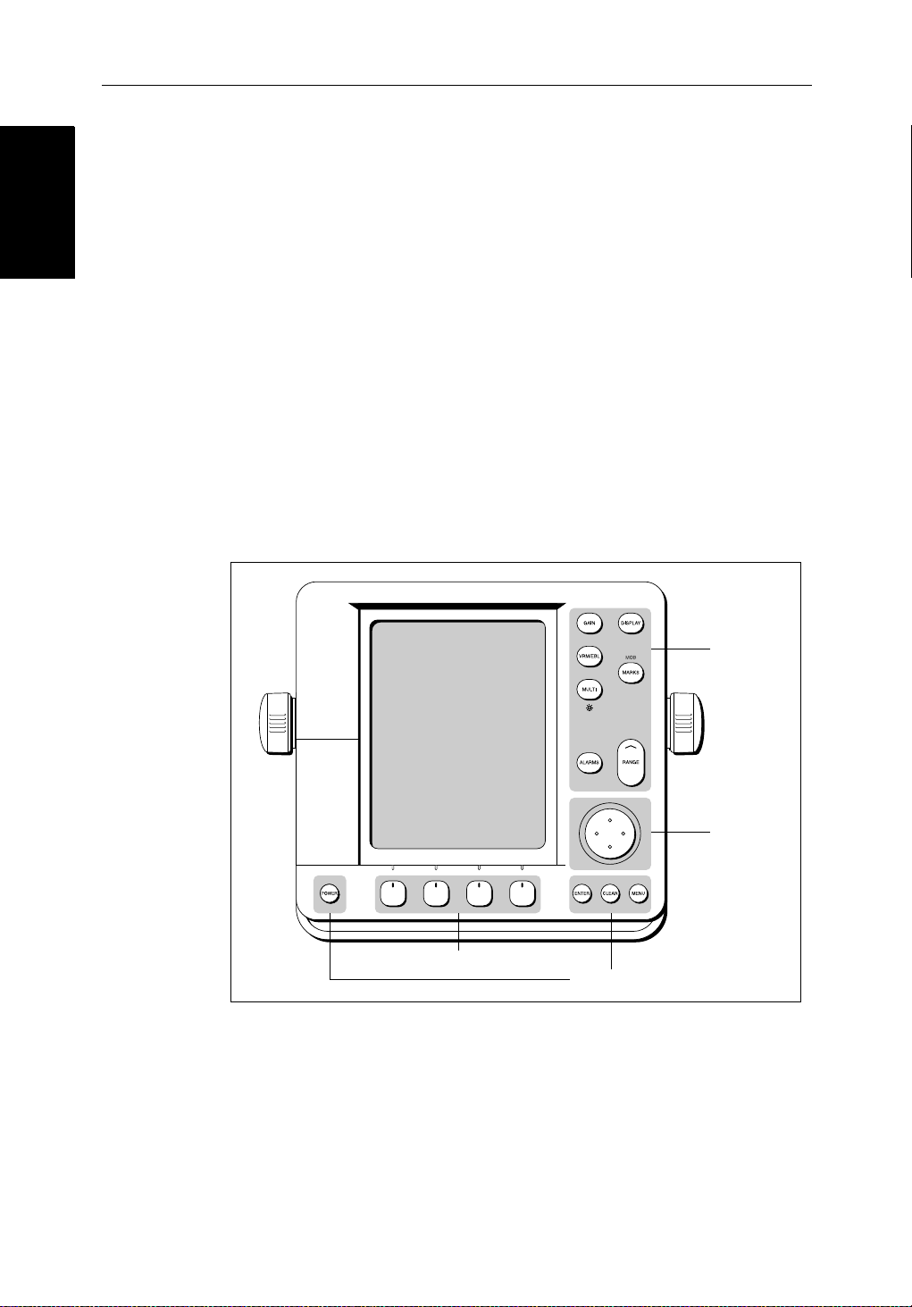
ThecontrolkeysareshowninFigure 1-6.Theyareback-litfornight-timeuse.
Whenyouuse a control, a help message is displayed at the topof the screen
(unlessyouswitchhelpoffas describedin Chapter 7).The following
paragraphsdescribethecontrolsandon-screenfacilitie s.
2
PLUS Series LCD Display
Figure 1-6: LCD Display Control Keys
Trackpad and Cursor
Thetrackpadhasseveralfunctions:
• Tomovethe cursor around the screen
Soft keys
Dedicated keys
Dedicated
keys
Trackpad
D3596-3
• Toselectan item from a pop-up menu
• Toadjusta variablesoftkey control

Chapter 1: Overview 1-17
Thecursorisused to:
• Selectapositiononthe screen.
• Selectanitem,e.g.guardzoneontheradar ,chart object on the chartplotter.
• Selectanareaof the radar image to zoom intoorpan the chart display..
Moving the Cursor
You can press on anyofthefoursectionsofthetrackpadtomovethecursorin
thatdirection(up, down,leftorright),or presstwosectionsat thesametimeto
movediagonally. Thecursormoves fasteras you continue to press the
trackpad.Thecurrentcursorpositionisshownin the cursor data box (if
selected).
Thecursoris normally displayedas a crosshair.However, ifyou have not
movedthecursorformore thanfiveseconds,whenyounextmoveitthe cursor
isoutlinedbya circle so it is easier to locate on the screen.
Note:During many operations you cannot move the cursoraroundthe
screen;if youcannotmove thecursorusingthetrackpad,checkthedefau ltsoft
keysaredisplayed(unlesstheyhave been switched OFF in system set up). If
not,pressENTER until theyaredisplayed.
Trackpad and Cursor
Trackpad and Cursor
Context-Sensitive Cursor Control
Thecursoris context-sensitive.Whenthecursorispositionedover special
featuresonthedisplaya text label appearstoidentifythefeatureas detailed in
Table 1-3 .
Moving and deleting items with the context-sensitive cursor
Someitemsontheradar/chartplotterscreen have informationassociatedwith
them.Mostinformationisdisplayedina data box. The context-sensitive
cursorallowsyouto move databoxes. It also allows you to moveordelete
otheritems,suchas radar guard zones. Further details of items that can be
movedor deletedare given in the appropriate sectionsthroughoutthis
handbook.
➤ Tomoveanydatabox or selectable item:
1. Use thetrackpadtopositionthecursorover theitemuntilthe item’slabelis
displayed.
2. Press ENTER totakecontrolof the item, use the trackpad to moveitto the
requiredposition.
3. Press ENTER againtofix the position,or press CLEAR to abandon the
move.
➤ Todeleteanitem:
1. Use thetrackpadtopositionthecursorover theitemuntilthe item’slabelis
displayedthenpressCLEAR.

1-18 hsb
Dedicated Keys
Dedicated Keys
Table 1-3: Context-Sensitive Cursor Text Labels
Text Label Feature Radar/Chart
BOX Data box (any type) Both
MOB Man Over Board marker Both
MRK Radar Mark Both
WPT Chart Waypoint Both
CTR Center of radar Radar
FLT Floating EBL/VRM Radar
GRD Guard zone Radar
MARPA MARPA Target Radar
SHM Ships Heading Marker Radar
VRM/EBL VRM and EBL, 1 or 2 Radar
ZMB Zoom box Radar
2
PLUS Series LCD Display
A
➟B
COG Course Over Ground vector Chart
HDG Heading vector Chart
POS Vessel’s position Chart
RTE Route leg Chart
TIDE Tide vector Chart
Dedicated Keys
The dedicated keys: DISPLAY, MARKS, GAIN, VRM/EBL, MULTI,
ALARMS, RANGE, ENTER, CLEAR, MENU andPOWER havefixed
functions;thefunctionsaresimilaronall Pathfinderdisplays.Forexample,
ALARMS is usedtosetupthe system alarmsonbothachartplotterandaradar.
Somekeys can be used in twoways:
• Press:Pressthekeymomentarilyandthenreleaseit.Thismethodisused
formostkey operations.
• Pressandhold:Pressthekeyandholdit downforthelengthoftimestated
(forexample,3 seconds),andthenreleaseit.
Whenyou press a dedicated key,oneofthefollowinghappens:
Ruler line Chart
i. The associatedoperationisactioned,e.g.changechartscale(RANGE).
ii. Apop-upmenu is displayed, providingfurtheroptions.
iii. Asetof soft keys is displayed, providing further functions.
 Loading...