


 Loading...
hsb2 PLUS Series Fishfinders
Owner’s
Handbook
Document number: 81195_2
Date: August 2002
hsb2 Plus Series Fishfinders |
iii |
hsb2 Plus Series Fishfinders Owner’s Handbook
August 2002
Intended Use
Raymarine hsb2 Plus Series Fishfinders are intended for recreational fishfinding. The combined Fishfinder/Chartplotter devices are intended for recreational fishfinding and course chartplotting. The optional chartplotter function is intended as an aid to navigation and should not be relied upon as a substitute for official navigation charts.
SAFETY NOTICES
This equipment must be installed and operated in accordance with the instructions contained in this manual. Failure to do so can result in personal injury and/or navigational inaccuracies. In particular:
1.HIGH VOLTAGE. The LCD display unit contains high voltages. Adjustments require specialized service procedures and tools only available to qualified service technicians – there are no user serviceable parts or adjustments. The operator should never remove the display unit cover or attempt to service the equipment.
2.NAVIGATION AID. The chartplotter unit is only an aid to navigation. Its accuracy can be affected by many factors, including equipment failure or defects, environmental conditions, and improper handling or use. It is the user’s responsibility to exercise common prudence and navigational judgements. This unit should not be relied upon as a substitute for such prudence and judgement.
EMC Conformance
All Raymarine equipment and accessories are designed to the best industry standards for use in the recreational marine environment.
The design and manufacture of Raymarine equipment and accessories conform to the appropriate Electromagnetic Compatibility (EMC) standards, but correct installation is required to ensure that performance is not compromised.
iv |
hsb2 Plus Series Fishfinders |
Preface
This handbook describes the following Raymarine hsb2 Plus Series Fishfinder Displays:
•L755RC Plus 7" Monochrome LCD Fishfinder Display with Chartplotter
•L760 Plus 7" Color LCD Fishfinder Display
•L760RC Plus 7" Color LCD Fishfinder Display with Chartplotter
•L1250 Plus 10.4" Color LCD Fishfinder Display
•L1250RC Plus 10.4" Color LCD Fishfinder Display with Chartplotter
The combined Fishfinder/Chartplotter display units include a cartridge holder assembly that contains two slots for C-MAP NT or NT+ chart cards. Fishfinder systems require an appropriate Raymarine transducer unit and inter-connecting cable. Details for selecting and installing the transducer are described in document number 81196, Transducers for Fishfinders Owner’s Handbook.
This handbook contains very important information on the installation and operation of your new fishfinder. In order to obtain the best results in operation and performance, please read this handbook thoroughly.
Raymarine’s Technical Services representatives or your local dealer will be available to answer any questions you may have.
TFT LCD Displays
The colors of the display may seem to vary when viewed against a colored background or in colored light. This is a perfectly normal effect that will be seen with all color LCD displays.
In common with all Thin Film Transistor (TFT) LCD displays, the screen may exhibit a few (less than 20) wrongly illuminated pixels. These may appear as black pixels in a light portion of the screen, or as colored pixels in black areas.
CAUTION:
To provide protection against the damaging effects of UV light, it is advisable to replace the sun cover provided when the color LCD display is not in use.
hsb2 Plus Series Fishfinders |
v |
Raymarine Products and Services
Raymarine products are supported by a network of Authorized Service Representatives. For information on Raymarine products and services, contact either of the following:
United States |
Raymarine, Inc. |
|
|
22 Cotton Road, Unit D |
|
|
Nashua, NH 03063-4219 |
|
|
USA |
|
|
Telephone: |
1-603-881-5200 |
|
|
1-800-539-5539 |
|
Fax: |
1-603-864-4756 |
Europe |
Raymarine Ltd |
|
|
Anchorage Park |
|
|
Portsmouth, Hampshire |
|
|
England PO3 5TD |
|
|
Telephone: |
+44 (0) 23 9269 3611 |
|
Fax: |
+44 (0) 23 9269 4642 |
Or, you may contact us on the World Wide Web at www.raymarine.com.
Warranty
To register your hsb2 Plus Series display unit ownership, please take a few minutes to fill out the warranty registration card found at the end of this handbook. It is very important that you complete the owner information and return the card to the factory in order to receive full warranty benefits.
Technical Accuracy
The technical and graphical information contained in this handbook, to the best of our knowledge, was correct as it went to press. However, the Raymarine policy of continuous improvement and updating may change product specifications without prior notice. As a result, unavoidable differences between the product and handbook may occur from time to time, for which liability cannot be accepted by Raymarine.
vi |
hsb2 Plus Series Fishfinders |
Raymarine is a registered trademark of Raymarine Limited. SeaTalk is a registered trademark of Raymarine Limited. hsb2 is a trademark of Raymarine Limited.
Pathfinder Plus is a trademark of Raymarine Limited.
This product contains technology provided under license by Acorn Group plc. The copyright of this intellectual property is acknowledged by Raymarine, Inc. as are Acorn’s trademarks and patents. Acorn’s world wide web address is http://www.acorn.com.
© Raymarine, Inc. 2002

Contents vii
Contents
|
|
EMC Conformance ......................................................................... |
iii |
|
|
Warranty .......................................................................................... |
v |
Chapter 1: |
Overview ......................................................................................... |
1-1 |
|
|
1.1 |
Introduction .................................................................................. |
1-1 |
|
|
General .......................................................................................... |
1-4 |
|
|
Introduction to hsb2 Systems ......................................................... |
1-5 |
|
|
Display Unit Features ................................................................... |
1-5 |
|
|
Operating Modes .......................................................................... |
1-6 |
|
1.2 |
The Fishfinder Display ................................................................. |
1-8 |
|
|
Fishfinder Options ........................................................................ |
1-9 |
|
|
Fishfinder Functions ................................................................... |
1-10 |
|
1.3 |
The Chartplotter Display ............................................................ |
1-12 |
|
|
Chartplotter Display Options ...................................................... |
1-13 |
|
|
Chartplotter Functions ................................................................ |
1-15 |
|
1.4 |
Operating Controls ..................................................................... |
1-16 |
|
|
Trackpad and Cursor ................................................................... |
1-17 |
|
|
Dedicated Keys ........................................................................... |
1-19 |
|
|
Soft Keys ..................................................................................... |
1-19 |
|
|
Pop-Up Menus ............................................................................ |
1-20 |
|
|
Database Lists ............................................................................. |
1-21 |
Chapter 2: |
Installation ..................................................................................... |
2-1 |
|
|
2.1 |
Introduction .................................................................................. |
2-1 |
|
|
Planning the Installation ............................................................... |
2-3 |
|
|
EMC Installation Guidelines ........................................................ |
2-3 |
|
2.2 |
Unpacking and Inspecting the Components ................................. |
2-5 |
|
2.3 |
Selecting the Equipment Location ................................................ |
2-7 |
|
|
Display Unit Mounting Location .................................................. |
2-7 |
|
2.4 |
Cable Runs .................................................................................. |
2-11 |
|
|
Power Cable ................................................................................ |
2-11 |
|
|
Transducer Cable ........................................................................ |
2-11 |
viii |
hsb2 Plus Series Fishfinders |
|
2.5 |
Mounting the Display Unit ......................................................... |
2-12 |
2.6 |
System Connections ................................................................... |
2-14 |
|
Display Unit Connection ............................................................ |
2-15 |
|
EMC Conformance ..................................................................... |
2-18 |
2.7 |
Integrated Systems ...................................................................... |
2-18 |
|
High Speed Bus (hsb2) ................................................................ |
2-19 |
|
SeaTalk and NMEA In ................................................................ |
2-22 |
|
Using the SeaTalk Auxiliary Junction Box ................................. |
2-26 |
|
Data Output ................................................................................. |
2-28 |
|
Data Conversion ......................................................................... |
2-28 |
2.8 |
Integrated System Checks .......................................................... |
2-29 |
|
Chart Display .............................................................................. |
2-29 |
|
Received Data ............................................................................. |
2-29 |
|
Transmitted Data ........................................................................ |
2-29 |
Chapter 3: Getting Started & Adjusting the Display ................................... |
3-1 |
|
3.1 |
Introduction .................................................................................. |
3-1 |
|
Conventions Used ......................................................................... |
3-1 |
|
Simulator ...................................................................................... |
3-1 |
3.2 |
Switching the Display On and Off ................................................ |
3-2 |
|
Simulator Mode ............................................................................ |
3-5 |
|
Changing the Lighting & Contrast (Monochrome LCD) ............. |
3-6 |
|
Changing the Brightness & Color Settings (Color LCD) ............. |
3-6 |
3.3 |
Controlling the Display ................................................................. |
3-9 |
|
Selecting the Mode of Operation .................................................. |
3-9 |
3.4 |
Fishfinder Display Control Functions ........................................ |
3-15 |
|
Viewing Data Boxes ................................................................... |
3-15 |
|
Changing the Scroll Speed .......................................................... |
3-15 |
|
Selecting the Power Setting ........................................................ |
3-17 |
|
Changing the Fishfinder Range .................................................. |
3-17 |
|
Selecting the Frequency .............................................................. |
3-20 |
|
Using Bottom Lock ..................................................................... |
3-21 |
|
Using A-Scope ............................................................................ |
3-23 |
|
Using Zoom ................................................................................ |
3-24 |
3.5 |
Chart Display Control Functions (Raychart Models) ................. |
3-26 |
|
Customizing the Screen Presentation Options ............................ |
3-26 |
Contents |
|
ix |
|
|
|
|
Moving Around the Chart ........................................................... |
3-28 |
Chapter 4: Fishfinder Operations ................................................................... |
4-1 |
|
4.1 |
Introduction .................................................................................. |
4-1 |
4.2 |
Interpreting and Adjusting the Fishfinder Image .......................... |
4-1 |
|
Fish Indications ............................................................................. |
4-2 |
|
Bottom Indications ....................................................................... |
4-3 |
|
Using White Line .......................................................................... |
4-4 |
|
Adjusting Display Gain (Sensitivity) ........................................... |
4-4 |
4.3 |
Fishfinder Data Window ............................................................... |
4-7 |
4.4 |
Using Alarms ................................................................................ |
4-8 |
4.5 |
Using VRM to Determine Depth & Distance from Boat .............. |
4-9 |
4.6 |
Waypoints ................................................................................... |
4-11 |
|
Placing a Waypoint ..................................................................... |
4-11 |
4.7 |
MOB ........................................................................................... |
4-13 |
Chapter 5: Standard Chart Operations .......................................................... |
5-1 |
|
5.1 |
Introduction .................................................................................. |
5-1 |
5.2 |
Using Chart Cards ......................................................................... |
5-2 |
|
Inserting a Chart Card ................................................................... |
5-2 |
|
Removing a Chart Card ................................................................ |
5-3 |
|
Displaying the Chart Data ............................................................. |
5-3 |
|
Displaying Chart Object and Source Information ........................ |
5-4 |
5.3 |
Working with Waypoints .............................................................. |
5-8 |
|
Introduction .................................................................................. |
5-8 |
|
Placing a Waypoint ....................................................................... |
5-9 |
|
Selecting a Waypoint .................................................................. |
5-12 |
|
Waypoint Data Display ............................................................... |
5-13 |
|
Editing the Waypoint Details ...................................................... |
5-13 |
|
Erasing a Waypoint ..................................................................... |
5-15 |
|
Moving a Waypoint .................................................................... |
5-15 |
|
Using the ST60 or ST80 Navigator Keypad ............................... |
5-16 |
5.4 |
Working with Routes .................................................................. |
5-18 |
|
Creating a New Route ................................................................. |
5-19 |
|
Saving the Current Route ............................................................ |
5-22 |
x |
hsb2 Plus Series Fishfinders |
|
|
Clearing the Current Route ......................................................... |
5-24 |
|
Retrieve a Route From the Database ........................................... |
5-24 |
|
Displaying Route Information .................................................... |
5-25 |
|
Using the Route List to Erase and Name a Route ....................... |
5-27 |
|
Editing a Route ........................................................................... |
5-28 |
5.5 |
Following Routes and Going to Points ....................................... |
5-30 |
|
Follow a Route ............................................................................ |
5-30 |
|
Target Point Arrival .................................................................... |
5-31 |
|
Other Follow Route Options ....................................................... |
5-32 |
|
Going To an Individual Target Point ........................................... |
5-33 |
|
Stop Follow or Stop Goto ............................................................ |
5-34 |
5.6 |
Transferring Waypoints and Routes ........................................... |
5-35 |
5.7 |
Using Tracks ............................................................................... |
5-39 |
|
Setting Up a Track ...................................................................... |
5-40 |
|
Clearing the Current Track ......................................................... |
5-40 |
|
Managing Tracks ........................................................................ |
5-40 |
|
SmartRoute ................................................................................. |
5-42 |
5.8 |
Typical Chart Scenarios .............................................................. |
5-43 |
|
Place and Goto a Waypoint ......................................................... |
5-44 |
|
Make and Follow a Route ........................................................... |
5-46 |
|
Review Your Passage Plan .......................................................... |
5-48 |
Chapter 6: Further Chart Operations ............................................................. |
6-1 |
|
6.1 |
Introduction .................................................................................. |
6-1 |
6.2 |
Measuring Distances Using the VRM/EBL Key .......................... |
6-2 |
6.3 |
Alarms and Timers ........................................................................ |
6-4 |
|
Alarm Reporting ........................................................................... |
6-4 |
|
Setting Alarms and Timers ........................................................... |
6-5 |
6.4 |
Man Overboard (MOB) ................................................................ |
6-6 |
6.5 |
Cursor Echo .................................................................................. |
6-7 |
6.6 |
Radar Overlay ............................................................................... |
6-7 |
6.7 |
GPS Setup ..................................................................................... |
6-9 |
6.8 |
Data Log Mode ........................................................................... |
6-10 |
Contents |
xi |
|
|
Chapter 7: Setting Up the System Defaults .................................................. |
7-1 |
7.1 Introduction .................................................................................. |
7-1 |
7.2 Changing the Set Up Parameters .................................................. |
7-2 |
7.3 System Set Up Parameters ............................................................ |
7-4 |
Data Boxes .................................................................................... |
7-6 |
Bearing Mode ............................................................................... |
7-6 |
Cursor Reference .......................................................................... |
7-6 |
Cursor Readout ............................................................................. |
7-7 |
Day/Night (Monochrome Display only) ...................................... |
7-7 |
Help ............................................................................................... |
7-7 |
Soft Keys ....................................................................................... |
7-7 |
Key Beep ...................................................................................... |
7-7 |
MOB Data ..................................................................................... |
7-8 |
Autopilot Pop Up .......................................................................... |
7-8 |
Menu Timeout Period ................................................................... |
7-8 |
Units .............................................................................................. |
7-8 |
Variation Source ........................................................................... |
7-8 |
Bridge NMEA Heading ................................................................ |
7-9 |
NMEA-Out Set Up ....................................................................... |
7-9 |
Cursor Echo (Systems with Radar Display) ............................... |
7-11 |
Date and Time Settings ............................................................... |
7-11 |
GPS SOG/COG Filter ................................................................. |
7-11 |
Compass Set Up .......................................................................... |
7-12 |
Language .................................................................................... |
7-12 |
Simulator .................................................................................... |
7-12 |
7.4 Fishfinder Set Up Parameters ..................................................... |
7-13 |
Target Depth ID .......................................................................... |
7-13 |
Color Bar ..................................................................................... |
7-13 |
Depth Digit Size .......................................................................... |
7-14 |
Sonar HSB Mode ........................................................................ |
7-14 |
Depth Offset ................................................................................ |
7-14 |
Speed Calibrate ........................................................................... |
7-14 |
Temperature Calibrate ................................................................ |
7-14 |
Sonar History .............................................................................. |
7-14 |
Depth Range (L1250 Plus and L1250RC Plus only) .................. |
7-15 |
Sonar Simulator .......................................................................... |
7-15 |
xii |
|
hsb2 Plus Series Fishfinders |
|
|
7.5 Chart Set Up Parameters (Raychart Models) .............................. |
7-16 |
|
|
|
Customize Chart ......................................................................... |
7-16 |
|
|
Plotter Mode ............................................................................... |
7-17 |
|
|
Chart Orientation ........................................................................ |
7-17 |
|
|
Object Information ..................................................................... |
7-18 |
|
|
Palette (Color LCDs only) .......................................................... |
7-18 |
|
|
Waypoint Options ....................................................................... |
7-18 |
|
|
Vectors ........................................................................................ |
7-18 |
|
|
Radar/Chart Synch (Systems with Radar Display) ..................... |
7-19 |
|
|
Datum Selection ......................................................................... |
7-19 |
|
|
Position Offset ............................................................................ |
7-19 |
Chapter 8: Maintenance and Problem Solving ............................................. |
8-1 |
||
|
8.1 |
Maintenance ................................................................................. |
8-1 |
|
|
Routine Checks ............................................................................. |
8-1 |
|
|
Cleaning Instructions .................................................................... |
8-1 |
|
|
EMC Servicing and Safety Guidelines ......................................... |
8-2 |
|
8.2 |
Resetting the System ..................................................................... |
8-3 |
|
8.3 |
Problem Solving ........................................................................... |
8-4 |
|
|
How to Contact Raymarine .......................................................... |
8-5 |
|
|
Worldwide Support ....................................................................... |
8-7 |
Appendix A: |
Specifications ............................................................................... |
A-1 |
|
|
|
hsb2 Plus Series Fishfinder Displays ............................................ |
A-1 |
Appendix B: Using the Auxiliary Junction Box ................................................ |
B-1 |
||
|
|
Raystar 112, 105, Apelco 182 and 182XT ................................... |
B-2 |
|
|
Autohelm GPS, Z260 and Z273 .................................................. |
B-3 |
|
|
Raystar 112LP (SeaTalk version) ................................................ |
B-4 |
|
|
Raystar 114 Combined GPS and Differential Beacon Receiver .. |
B-5 |
|
|
Raystar 120 WAAS Satellite Differential Receiver ..................... |
B-6 |
Appendix C: C-MAP Chart Card Features ........................................................ |
C-1 |
||
Appendix D: SeaTalk and NMEA Data .............................................................. |
D-1 |
||
Appendix E: |
Abbreviations ............................................................................... |
E-1 |
|

Chapter 1: Overview |
1-1 |
|
|
Chapter 1: Overview
1.1 Introduction
This handbook describes the following hsb2 (High Speed Bus) Plus Series Fishfinder displays:
Fishfinder |
Display Type |
Display Size |
Chartplotter |
|
|
|
|
L755RC Plus |
Monochrome LCD |
7 inch |
Yes |
|
|
|
|
L760 Plus |
Color LCD |
7 inch |
No |
L760RC Plus |
Color LCD |
7 inch |
Yes |
|
|
|
|
L1250 Plus |
Color LCD |
10.4 inch |
No |
L1250RC Plus |
Color LCD |
10.4 inch |
Yes |
|
|
|
|
Raymarine hsb2 Plus Series Fishfinders use the latest processor and sonar technology for accurate performance and echo detection. Units feature 7" or 10.4" daylight viewable monochrome or color LCD displays and the Raychart (RC) models include a full C-Map NT/NT+ Chartplotter. With up to 600 watts output power and dual frequency operation, hsb2 Plus Series Fishfinders provide performance from 1 up to 3000 ft. In fact, the L1250 Plus and L1250RC Plus units offer 1000 watts power and a depth range up to 5000 ft.
Use the High Speed Bus (hsb2), SeaTalk and NMEA interfaces to provide an integrated system with additional devices, such as Pathfinder Plus Radar, Raymarine Autopilot and Raystar Wide Area Augmentation System (WAAS) GPS products.
Connecting an hsb2 Series Plus Fishfinder to an hsb2 Series Pathfinder Plus Radar and to an hsb2 Series Plus Chartplotter enables fishfinder, radar, and chart data to be displayed on all three units. Similarly, chart data can be repeated on a fishfinder-only device from any via hsb2 from any other hsb2 device with chart capabilities.
This handbook describes the display unit controls and details both fishfinder and chart operations. Controls that are specific to either fishfinder or chartplotter are described in fishfinder or chart sections/chapters.
Note: Many illustrations in this handbook show example screens. The screen you see on your display depends on your system configuration and set up options, so it may differ from the illustration.
Introduction

Introduction
1-2 |
hsb2 Plus Series Fishfinders |
How to Use This Handbook
If you are installing the display system yourself, you should read Chapter 2 before you start the installation. This chapter also provides information that will be useful if you are connecting your hsb2 Plus Series system to other equipment.
For an overview of the display unit controls, the fishfinder and the chartplotter systems, read Chapter 1. Chapter 3 will help you start using your system.
For detailed information on fishfinder operations refer to Chapter 4.
For chartplotter operating details, refer to Chapter 5 and Chapter 6.
To change the system set up defaults, read Chapter 7.
Chapter 2 provides planning considerations and detailed instructions for installing the fishfinder display unit. It should be referred to when you are ready to install the system. Details to connect the display to other equipment via hsb2, NMEA and SeaTalk are also provided.
Chapter 3 explains how to start using the display and describes how to use some of the basic fishfinder and chart functions. Chapter 3 also provides operating guidelines for typical chartplotter scenarios; these guidelines introduce you to many of the chartplotter functions.
Chapters 4 provides detailed operating information for the fishfinder functions - selecting depth range limits, adjusting gain, color and STC, setting alarms, using the VRM marker, marks and man overboard.
Chapter 5 provides detailed operating information for the standard chartplotter functions - using chart cards, plotting waypoints and routes, following routes and showing tracks.
Chapter 6 provides detailed operating information for further chart functions, including measuring distances, man overboard and cursor echo. It includes instructions for setting up a differential GPS.
Chapter 7 provides instructions for setting up your system to suit your preferences. You should read this chapter to determine how to set up the fishfinder and chartplotter system defaults.
Chapter 8 provides information on user maintenance, and what to do if you experience problems.
The Appendices provide additional information that you may find useful: Appendix A lists the technical specifications for the fishfinder and for the chartplotter.
Appendix B provides details on connecting the display unit to specific GPS systems.

Chapter 1: Overview |
1-3 |
|
|
Appendix C defines the chart features shown on the chart display.
Appendix D defines the SeaTalk and NMEA data that is transferred on integrated systems.
A List of Abbreviations, Index and warranty information are included at the end of the handbook.
A summary of the fishfinder and chartplotter controls are provided on the Quick Reference Cards supplied with your system.
Terminology
The following terminology is used to describe the various display unit configurations:
Master |
A unit capable of sourcing specific data such as |
|
fishfinder, chart, or radar data. |
Repeater |
A unit capable of displaying data, such as radar, |
|
from the High Speed Bus. |
Fishfinder Display |
Unit providing Fishfinder Master and Radar |
|
Repeater functionality. The L755RC, L760RC, |
|
and L1250RC Plus displays also provide Chart |
|
Master functionality. |
Radar Display |
Unit providing Radar Master, Fishfinder |
|
Repeater and Chart Reader functionality. |
Chart Display |
Unit providing Chart Master, Fishfinder |
|
Repeater and Radar Repeater functionality. |
Combined Display |
Unit providing both Fishfinder and Chart or |
|
Radar and Radar Repeater functionality. |
Integrated System |
Additional instruments are connected via hsb2, |
|
SeaTalk or NMEA interfaces. |
hsb2 |
High Speed Buslinks up to ten compatible dis- |
|
play units. For full display and control between |
|
hsb2 Plus Series display units, the units must be |
|
connected via hsb2 and SeaTalk. |
Introduction
General
1-4 |
hsb2 Plus Series Fishfinders |
General
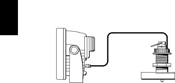
The hsb2 Plus Series Fishfinder system, illustrated below, is comprised of the 7" or 10.4" LCD display unit, fishfinder transducer, and associated cables.
Figure 1-1: Basic Fishfinder System
Display Unit
The hsb2 Plus Series LCD display unit is waterproof to CFR46 and can be installed either above or below deck.
The unit includes:
•7" or 10.4" LCD display
•Trackpad
•Eleven dedicated (labeled) control keys
•Four soft keys (unlabeled) whose functionality changes
•Two slots for the C-MAP NT® or NT+ chart cards (Raychart models only)
The display and keys can be illuminated for night-time use.
Transducer
The hsb2 Plus Series Fishfinders require a transducer, either thru-hull, in-hull, or transom-mount.
Transducers can measure water depth, temperature, distance traveled, and/or speed. It is important to position your transducer correctly. For details on transducers, including location and installation instructions, see document number 81196, Transducers for Fishfinders Owner’s Handbook.
Note: If speed and temperature are being input via SeaTalk, these values are displayed instead of the speed and temperature inputs from the transducer.

Chapter 1: Overview |
1-5 |
|
|
Introduction to hsb2 Systems
The hsb2 (High Speed Bus) connection enables transfer of data among compatible units. For example, fishfinder data is transferred from the fishfinder (the master display) via the hsb2 connection and can be displayed and controlled on any other hsb2 Plus Series LCD or CRT display (the repeater display). However, if you change, say, depth range on one display, it affects all displays showing fishfinder or fishfinder/chart overlay.
In particular, you can connect your hsb2 Series Plus Fishfinder to a remote hsb2 Series Pathfinder Plus Radar and then to a remote hsb2 Series Plus Chartplotter to provide fishfinder, chart, and radar functionality on all three displays.
Full functionality of the fishfinder is achieved when it is part of an integrated system, with other equipment (in addition to other hsb2 Plus units) connected via SeaTalk or NMEA 0183. Data from this equipment including position and heading is displayed on the display and is used in calculations.
It is possible to connect up to ten hsb2 Plus Series LCD or CRT displays to provide an integrated system. Earlier HSB (non-Plus) Display units can be upgraded to provide hsb2 compatibility. See Connecting hsb2 Plus Series Displays on page 2-20 for details.
Note: Please contact Raymarine Customer Service or your authorized Raymarine dealer about upgrading your existing HSB (non-Plus) display units to provide full hsb2 Plus functionality.
The hsb2 system can include several chartplotter displays, each with two chart cartridge slots. Each display can access two local and up to six remote chart cartridges. Charts can be controlled independently on each display, even when a remote chart cartridge is being used. Details on connecting the equipment are given in Chapter 2.
Display Unit Features
Fishfinder
•Displays depth, speed, and temperature, if the transducer is so equipped
•Dual or split frequency fishfinder display – 50 kHz, 200 kHz
•Display options – fishfinder window, zoom, bottom lock and A-Scope
•Uses position data from GPS, DGPS, WAAS or Loran-C technology
•Displays and transfers hsb2, SeaTalk and NMEA data
•Provides full control of data from other hsb2 instruments
•Half-screen windows to display additional data: depth/temperature graph, Course Deviation Indicator (CDI), Bearing and Distance Indicator (BDI), navigation data
Introduction to hsb2 Systems

Modes Operating
1-6 |
hsb2 Plus Series Fishfinders |
Chartplotter
•Displays information from the C-MAP NT® and NT+ chart cards (C-Cards)
•Three full-screen operating modes: Fishfinder, Chart, Data Log (if appropriate data is available)
•View fishfinder and chart simultaneously
•Choice of chart orientation: Head Up, Course Up and North Up
Operating Modes
If you have a combined Fishfinder/Chartplotter unit, or have an hsb2 Plus Series Chartplotter connected to a Fishfinder, three full-screen modes – fishfinder, chart and data log are available; you select the operating mode using the DISPLAY key as described in Chapter 3.
You can also set Windows On to split the display into two half-screen windows to show supplementary data, or to display fishfinder and chart simultaneously. The main operating mode (fishfinder or chart) is displayed in the upper window; you choose what is displayed in the lower window.
In addition, if you have an hsb2 Series Pathfinder Plus Radar display connected, you can set the display to radar mode; this provides similar functionality to a combined Pathfinder Radar/Chartplotter.
If you only have an L760 Plus or L1250 Plus fishfinder-only unit connected, only fishfinder mode is available.

Chapter 1: Overview |
1-7 |
|
|
Half -Screen Window Options
The following information, if available on your system, can be shown:
Table 1-1: |
Window Options for Combined/Integrated Systems |
||
|
|
|
|
Full-screen |
|
Half-screen Window Options - |
Half-screen Window Options - |
mode |
|
Fishfinder/Chart Display only |
Fish/Chart + Radar Displays |
|
|
|
|
Fishfinder Mode |
Depth/temp, Chart, CDI, BDI, or Data |
Depth/temp, Chart or CDI, BDI |
|
|
|
|
|
Chart Mode |
|
CDI, BDI, Nav Data or Fishfinder |
CDI, BDI, Nav Data, Fishfinder or |
|
|
|
Radar |
|
|
|
|
Radar Mode |
|
Not Available |
CDI, BDI, Chart or Nav Data |
|
|
|
|
Data Log Mode |
|
Half-screen Windows not available |
Windows not available |
|
|
|
|
•Chart display (when in Fishfinder or Radar mode) Fishfinder display (when in Chart mode):
Radar display (when in Chart mode):
If data is available, either as a function of the combined display unit or via the hsb2 link, it can be displayed.
•Depth/temp graph (Fishfinder mode): This shows a plot water temperature and depth against time.
•Data (Fishfinder mode): This option splits the fishfinder vertically. The left hand window displays data boxes; there are three different sets of data (A, B and C) that you can select for display.
•CDI: This gives the Course Deviation Indicator graphical display, with data relating to the target waypoint.
•BDI: This gives the Bearing and Distance Indicator graphical display, with data relating to the target waypoint.
•Nav Data (Chart mode): This shows sixteen data boxes, providing navigational data in the units specified in your set up. Note that up to 6 of these data boxes are also available as a user-selectable group (see Section 7.3).
For details on the radar, refer to the Owner’s Handbook supplied with your radar.
Note: MARPA functionality is available on the fishfinder display if you have an integrated system with a Pathfinder radar master display that includes MARPA as a primary function.
Details on selecting windows are given in Chapter 3.
Operating Modes

Fishfinder The
Display
1-8 |
hsb2 Plus Series Fishfinders |
1.2 The Fishfinder Display
When you first turn the display unit on and select fishfinder mode, the scrolling bottom graph is displayed. This is a graphical representation of the echoes seen by the Fishfinder. As time passes, this display scrolls from right to left and becomes a record of the echoes seen. A typical display is shown in
Figure 1-2.
The images at the right hand side of the display are the most recent echoes. Some echoes indicate fish, and others show the bottom. It can also indicate bottom structures, such as a reef or shipwreck. The upper and lower depth range limits are shown.
The fishfinder screen includes a status bar that displays transducer frequency and indicates which auto settings are enabled (Gain, Color Gain, Range, Zoom and Frequency), and alarm status (fish and shallow/deep water depths).
You can customize the fishfinder by choosing what is displayed and how it is displayed (including language and units). For example, you can set the scroll speed of the bottom graph display, and you can select the range to adjust the amount of detail displayed.
You can view the cursor position and a variety of data (such as speed, heading and depth) from the transducer and other equipment in user-selectable data boxes. These data boxes can be moved around the screen and they can be switched on or off.
Chapter 3 includes details on adjusting the display, other set up options are described in Section 7.3 and Section 7.4.
Chapter 1: Overview |
1-9 |
|
|
|
" # |
|
|
! |
|
$ |
||
|
||
|
||
|
||
|
|
|
|
|
% #
&
|
|
AUTO GCRZFH |
50kHz SD |
|
|
|
|
|
|
|
|
|
|
|
|
|
|
|
|
|
|
|
|
||||||||||
|
|
|
|
|
|
|
|
|
|
|
|
|
|
|||
|
|
|
|
0 |
|
|
|
|
|
|
||||||
|
|
|
|
|
|
|
|
|
||||||||
|
|
|
|
8 |
|
|
|
|
|
|
|
|
|
|
||
|
|
|
|
|
|
|
|
|
|
|
|
|
|
|||
|
|
|
|
|
|
|
|
|
|
|
|
|||||
|
|
|
|
|
|
|
|
|
|
|
|
|
||||
|
|
|
|
|
|
|
|
|
|
|
|
|
||||
|
25 |
|
|
|
|
|
|
|
|
|||||||
|
|
|
|
|
|
|
||||||||||
|
|
|
|
|
|
|
|
|
|
|
|
|
|
|||
|
|
|
|
38 |
|
|
|
|
|
|
|
|
|
|||
|
|
|
|
|
|
|
|
|
|
|
|
|||||
|
|
|
|
45 |
|
|
|
|
|
|
|
|
|
|
|
|
52 |
50 |
|
|
|
|
|
|
|
|
|
||||||
|
|
|
|
|
|
|
||||||||||
|
|
|
|
|
|
|
|
|
|
|
|
|
|
|
|
|
75

|
ft |
100 |
|
|
|
|
|
|
FREQUENCY ZOOM BTM.LOCK A-SCOPE
Figure 1-2: Typical Fishfinder Display
Fishfinder Options
The fishfinder provides controls to select additional modes:
•Frequency – you can select the transducer frequency, 50 kHz for wide coverage and deep water, 200 kHz for a detailed view, both frequencies simultaneously or auto-frequency. The default setting is auto-frequency, which determines the optimum frequency of operation based on the current depth.
•Bottom Lock – changes the operating mode to re-set the bottom. It provides a bottom-up view: the bottom is used as the reference, its image is flattened and depths are displayed here. Bottom lock mode is used primarily to filter-out the bottom structure and display fish details only.
Fishfinder Options
Functions |
Fishfinder |
|
|
1-10 |
hsb2 Plus Series Fishfinders |
•A-Scope – displays a real-time image of the bottom structure and fish directly below the transducer. The A-Scope window also displays the patented Bottom Coverage width indication.
•Zoom – enlarges all or part of the bottom graph display. You can select x2, x4 or x6 magnification and the zoom area can be automatically or manually adjusted.
You can select Zoom, Bottom Lock or A-Scope to be vertically split with the bottom graph display. Alternatively, Zoom or Bottom Lock can be displayed in place of the bottom graph display.
If you choose dual frequency, the scrolling bottom graph is displayed in both frequencies, split horizontally. Zoom, Bottom Lock or A-Scope can be displayed with the dual frequency graph.
All of these options are available when the fishfinder is displayed in a halfscreen window.
Fishfinder Functions
The hsb2 Plus Series Fishfinder includes the following functions:
•Automatic or manual selection of scroll speed for bottom graph display
•Automatic or manual selection of transducer frequency
•Automatic or manual selection of upper and lower depth range limits
•Adjustment of foreground/background color and image color threshold (contrast control on the L755RC Plus monochrome display)
•Adjustment of Gain, Color Gain and STC
•Set up alarms for Fish, Shallow water and Deep water
•VRM marker to determine depth and distance
•Add marks to record important or dangerous locations
•Man Overboard (MOB) to navigate back to a person or object
Operation of these fishfinder functions is described in Chapter 3 and
Chapter 4.

Chapter 1: Overview |
1-11 |
|
|
AUTO G Z |
SPLIT |
|
|
|
|
AUTO G Z |
SPLIT |
||
|
|
0 |
|
|
0 |
|
|||
35 |
25 |
25 |
|
|
35 |
25 25 |
|
|
|
|
|
|
|
||||||
50 |
50 |
75 |
75 |
200kHz |
100 |
|
200kHz |
100 |
|
7.9 |
|
|
|
||||||||||||||||||||||||
|
|
|
|
||||||||||||||||||||||||||||||
|
50kHz |
0 |
|
|
50kHz |
0 |
|
|
|
|
|
|
|
|
|
|
|
|
|||||||||||||||
|
|
|
|
|
25 |
|
|
|
|
|
|
|
|
|
|
25 |
|
|
|
|
|
|
|
|
|
|
|
|
|
|
|
||
35 |
|
|
|
25 |
|
35 |
|
|
|
|
|
|
|
|
|
|
|
|
|
|
|
|
|
|
|||||||||
|
|
|
|
|
|
|
25 |
|
|
|
|
|
|
|
|
|
|
|
|
|
|
||||||||||||
|
|
|
|
|
|
|
|
|
|
|
|
|
|
|
|
|
|
|
|
|
|
|
|
|
|
||||||||
|
|
|
|
|
50 |
|
|
|
|
|
|
|
|
50 |
|
|
|
|
|
|
|
|
|
|
|
|
|
|
|||||
|
|
|
|
|
75 |
|
|
|
|
|
|
|
75 |
|
|
|
|
|
|
|
|
|
|
|
|
|
|
||||||
|
|
|
|
|
|
|
|
|
|
|
|
|
|
|
|
|
|
|
|
|
|
|
|
|
|
||||||||
|
|
|
|
|
|
|
|
|
|
|
|
|
|
|
|
|
|
|
|
|
|
|
|
|
|
||||||||
|
|
|
|
ft |
100 |
|
|
|
|
|
ft |
100 |
|
52.3 |
|
||||||||||||||||||
|
|
|
|
|
|
|
|
|
|
|
|||||||||||||||||||||||
|
|
|
|
|
|
|
|
|
|
|
|
|
|
|
|
|
|
|
|
|
|
|
|
|
|
|
|
|
|
|
|
|
|
|
FREQUENCY |
|
|
ZOOM |
|
BTM.LOCK |
|
A-SCOPE |
|
|
FREQUENCY |
|
|
ZOOM |
|
BTM.LOCK |
|
A-SCOPE |
|
||||||||||||||
AUTO G Z |
|
200kHz |
|
|
|
|
||
|
|
|
|
|
0 |
|
||
|
20 |
|
|
20 |
|
|
|
|
|
|
|
|
|
|
|||
|
15 |
|
|
|
|
|
||
|
|
|
|
|
||||
|
|
|
40 |
|
|
|
||
|
|
|
|
|
|
|||
|
10 |
|
|
|
|
|
||
|
|
|
|
|
|
|||
|
|
|
|
|
|
|
||
|
|
|
|
|
|
|
||
|
6 |
|
|
60 |
|
|
|
|
BL |
5 |
|
|
|
|
|
||
|
|
|
|
|
||||
|
|
|
|
|
|
|||
|
|
|
|
|
|
|||
|
|
|
|
|
|
|
|
|
|
|
ft |
|
80 |
|
|||
|
|
|
|
|||||
|
|
|
||||||
|
|
|||||||
FREQUENCY ZOOM BTM.LOCK A-SCOPE
AUTO G |
SPLIT |
|
|
|
|
||||
|
|
|
|
|
|
0 |
|
||
|
|
|
|
|
|
25 |
|
|
|
|
|
|
|
|
|
|
|
||
|
|
|
|
|
|
50 |
|
|
|
|
|
|
|
|
|
|
|
||
200kHz |
|
|
|
|
75 |
|
|
||
|
|
|
|
|
|
||||
|
|
|
|
|
|
||||
|
|
|
|
100 |
|
||||
|
|
|
|
|
|||||
|
50kHz |
|
|
|
|
0 |
|
||
|
|
|
|
|
|
25 |
|
|
|
|
|
|
|
|
|
|
|
||
X4 |
|
|
|
|
50 |
|
|
||
|
|
|
|
|
|
||||
|
|
|
|
|
|
||||
|
|
|
|
75 |
|
|
|||
|
|
|
|
|
|
|
|
||
|
|
|
|
|
|
|
|
||
|
|
ft |
|
|
|
100 |
|
||
|
|
|
|
|
|
||||
|
|
|
|
|
|
|
|
|
|
|
FREQUENCY |
ZOOM |
|
BTM.LOCK |
|
A-SCOPE |
|||
|
|
|
|
|
|
|
|
|
|
|
|
|
Figure 1-3: Fishfinder Display Options
Fishfinder |
Functions |
|
|

Chartplotter The
Display
1-12 |
hsb2 Plus Series Fishfinders |
1.3 The Chartplotter Display
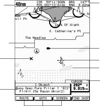
The L755RC, L760RC and L1250RC Plus Fishfinders include a Chartplotter. The chartplotter includes a small-scale world map and detailed navigation information is displayed when a cartographic chart card is installed. The details displayed depend on the chart zoom level selected. A plotter mode is provided to enable route plotting and tracking at large scales even when a chart card is not installed A typical chartplotter screen is shown in Figure 1-4.
Note: For an L760 Plus or L1250 Plus fishfinder-only unit to have access to chartplotter functionality, it must be connected to an hsb2 Plus Series Chartplotter device. This is discussed fully in the section Integrated Systems on page 2-18.
The chartplotter uses position information from a GPS, DGPS, WAAS, or Loran-C instrument. Once the position fix has been established, your vessel’s position, if on screen, is shown as a boat shape pointing in the direction of the current heading (or COG if heading data is not available). If no heading or COG data is available, the vessel is shown as a circle.
The chartplotter screen includes a status bar that displays chart scale, with either cursor position, range and bearing or, when the cursor is homed to the vessel (by pressing FIND SHIP), vessel position, Speed Over Ground (SOG), Course Over Ground (COG) and fix type (VES POS, DIF FIX or SD FIX). The status bar also indicates if radar/chart overlay is switched on.
Any waypoints you have placed are displayed (unless you turned them off in Chart Set Up as described in Chapter 7) and the current route is shown. Information can be viewed on-screen by positioning the cursor over a waypoint, current route or chart object. The chartplotter screen can also show additional information, depending on your currently selected options, set up selections and data available from other equipment.
An example chart display, in its default configuration, with a chart card installed, is shown in the following illustration.
Several functions are available to control the display as follows:
•Zoom in/out and Pan the Display
•Offset the Chart or Center the Chart around the Vessel
•Overlay Radar Targets onto the Chart Display
•Synchronize the Chart and Radar (if radar data is available)
Operation of these functions is described in Chapter 3.
Chapter 1: Overview |
1-13 |
|
|
Chartplotter Display Options
Set up options allow you to customize the chart by choosing what is displayed (including cartographic features), how it is displayed (including language and units), heading mode and how the chartplotter operates with other hsb2 units. You can also view the cursor position and a variety of data from other equipment (for example, speed, heading, depth, wind, and tide information) in a set of user-selectable data boxes. The cursor box and user-selected data boxes can be moved around the screen and they can be turned on or off. You can also obtain autopilot status and locked heading information.
Display options are provided in System Set Up and Chart Set Up as described in Chapter 7. Chart set up options allow you to customize the chart by selecting:
•What cartographic features and level of detail are displayed
•The chart color palette (shade or sunlight)
•Chart orientation (north up, head up or course up), datums and position offset
•How waypoints are displayed (symbols and numbers) and how chart object information is displayed
•Vectors for heading, COG and tide
In addition Screen Presentation Options, described in Chapter 3 are provided to switch:
•Cursor Box and Databoxes On/Off
•Chart Grid On/Off
•Custom Chart Details On/Off
Note: When you turn the display off and on again, these settings are retained in memory.
Chartplotter |
Display Options |
|
|
1-14 |
hsb2 Plus Series Fishfinders |
Options Display |
Chartplotter |
|
|
Chart Range
Chart Boundary
Waypoint
Object data box - for object selected by cursor
Status Bar
Vessel Position
Cursor -
selecting chart object
Depth Area
Cursor position box
Shows the current cursor position as either Range/Bearing or Lat/Long. You can move this box to your preferred position on
the screen or turn it off.
Default soft key labels
These can be turned off: press any soft key to redisplay them. Different labels are displayed when you press a key.
D4275-3
Figure 1-4: Typical Chartplotter Display
Custom Chart Details
The chartplotter set up options include a sub-menu to customize the cartographic features. This menu allows you to switch features On, Off, or control them using the CUSTOM soft key. The factory default settings for the Custom chart options are as follows:
ON: Chart text, chart boundaries, depth contours, navigation marks and land features.
OFF: Caution and routing data.
CUSTOM: Spot sounding, light sectors, marine features.
Note: The factory default for the CUSTOM settings is ON.
Icons are displayed in detail, depth shading limit is 10 m and depth contour display is 0-100 m.
A complete list of chart features is given in Appendix C.
Chapter 1: Overview |
1-15 |
|
|
Chartplotter Functions
The hsb2 Plus Series Chartplotter includes the following functions:
•Display C-MAP NT and NT+ C-Card chart information including Ports and Tides (if available)
•View chart information (if available) for the Nearest Port
•Place, Move, Erase and Edit a Waypoint
•Goto Waypoint or Cursor
•Create, Save, Name, Edit and Follow a Route
•Review Route and Waypoint Lists
•Display vessel’s track; Save and Name the Track for re-call to screen
•Measure Chart Distances and Bearings on-screen
•Set Up Alarms and Timers
•Man OverBoard (MOB) to navigate back to a missing person or object
•Differential GPS set up page
Operation of these functions is described in Chapter 5 and Chapter 6.
Chartplotter |
Functions |
|
|
Controls Operating
1-16 |
hsb2 Plus Series Fishfinders |
1.4 Operating Controls
You operate the fishfinder and chart systems using a variety of controls:
•A trackpad providing up, down, left, right and diagonal control of an on screen cursor
•Eleven dedicated (labeled) control keys
•Four soft keys with labels displayed on the screen
•Pop-up menus, displayed on-screen, from which you select options
•Database lists, displayed on-screen, which enable you to edit items
Note: The cursor is the cross-hair symbol (+) visible on the display. You move the cursor using the trackpad and use it to select a position or item on the chart.
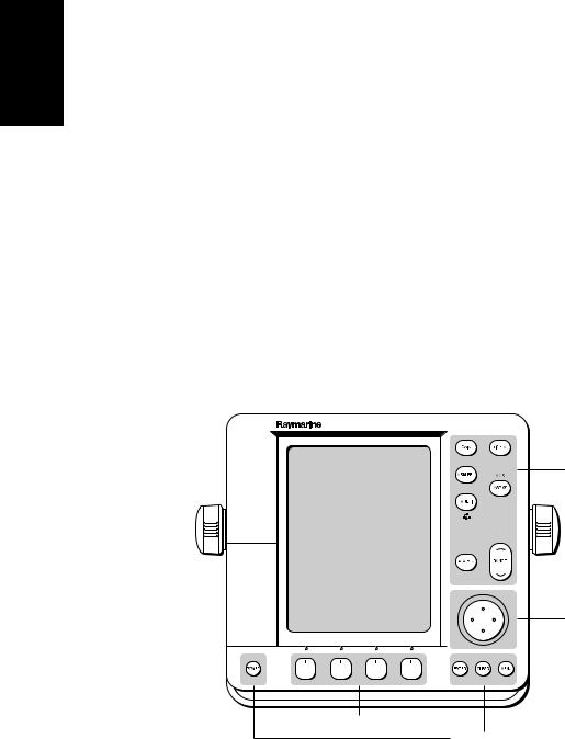
The control keys are shown in Figure 1-6. They are back-lit for night-time use when the display brightness is dimmed. When you use a control, a help message is displayed at the top of the screen (unless you switch help off as described in Chapter 7). The following paragraphs describe the controls and on-screen facilities.
Dedicated keys
Trackpad
D3596-4
Soft keys
Dedicated keys
Figure 1-5: 7" LCD Display Control Keys
Chapter 1: Overview |
1-17 |
|
|
|
|
|
|
|
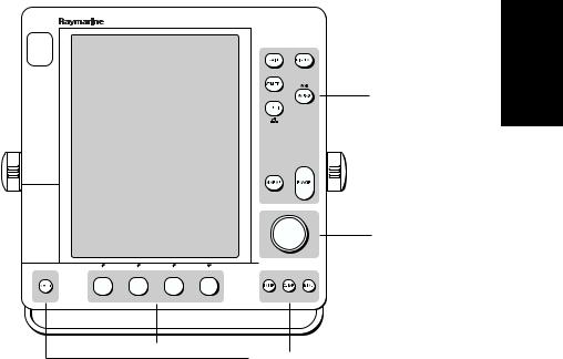
Dedicated keys
Trackpad
D5440-1
Soft keys
Dedicated keys
Figure 1-6: 10.4" LCD Display Control Keys
Trackpad and Cursor
The trackpad has several functions:
•To move the cursor around the screen
•To select an item from a pop-up menu
•To adjust a variable soft key control
The cursor is used to:
•Select a position on the screen
•Select an item, for example, chart object on the chartplotter
•Pan the chart display
Moving the Cursor
You can press on any of the four sections of the trackpad to move the cursor in that direction (up, down, left or right), or press two sections at the same time to move diagonally. The cursor moves faster as you continue to press the trackpad. The current cursor position is shown in the cursor data box (if selected).
Cursor
Trackpad and

and Trackpad
Cursor
1-18 |
hsb2 Plus Series Fishfinders |
Note: During many operations you cannot move the cursor around the screen; if you cannot move the cursor using the trackpad, check the default soft keys are displayed (unless they have been switched OFF in system set up). If not, press ENTER until they are displayed.
The cursor is normally displayed as a crosshair. However, in chart mode, if you have not moved the cursor for more than five seconds, when you next move it the cursor is outlined by a circle so it is easier to locate on the screen.
Context-Sensitive Cursor Control
The cursor is context-sensitive. When the cursor is positioned over special features on the display a text label appears to identify the feature as follows:
Table 1-2: |
Context-Sensitive Cursor Text Labels |
|
|
|
|
|
|
Text Label |
Feature |
Fishfinder/Chart |
|
|
|
|
|
BOX |
|
Data box (any type) |
Both |
|
|
|
|
MOB |
|
Man Over Board marker |
Both |
|
|
|
|
WPT |
|
Waypoint |
Both |
|
|
|
|
BL |
|
Bottom Lock |
Fishfinder |
|
|
|
|
VRM |
|
Variable Range Marker |
Fishfinder |
|
|
|
|
ZOOM |
|
Zoom |
Fishfinder |
|
|
|
|
A B |
|
Ruler line |
Chart |
|
|
|
|
COG |
|
Course Over Ground vector |
Chart |
|
|
|
|
HDG |
|
Heading vector |
Chart |
|
|
|
|
POS |
|
Vessel’s position |
Chart |
|
|
|
|
RTE |
|
Route leg |
Chart |
|
|
|
|
TIDE |
|
Tide vector |
Chart |
|
|
|
|
Chart Icons |
|
Various |
Chart |
|
|
|
|
Some items on the fishfinder/chartplotter screen, such as the cursor have information associated with them. Most information is displayed in a data box. The context-sensitive cursor allows you to move databoxes. In the case of Fishfinder VRM data, depth is displayed on the right hand side of the horizontal indicator, and distance is displayed at the top of the vertical indicator.
Loading...