


Cat. No. 19-1127
OWNER’S MANUAL
Please read before using this equipment.
HTX-252
2–Meter Amateur
FM Mobile Transceiver

FEATURES
Your RadioShack HTX-252 2–Meter FM Mobile Transceiver is a compact and versatile transceiver, perfect either in your vehicle or in your home. Vehicle cables and mounting hardware are supplied. Add an optional base-station antenna, cable, and a power supply to make it your home transceiver. It is an all-around ideal choice for your amateur communications needs.
Note: You must have a Technician Class or higher Amateur Radio Operator’s License and a call sign issued by the FCC to legally transmit using this transceiver. Transmitting without a license carries heavy penalties. Getting a license is easier than ever. See “Introduction to Amateur Radio” on Page 7 for more information.
Here are some of your transceiver’s features.
High (25 Watt) and Low (10 Watt) Power Settings — let you select the best power setting according to communication guidelines.
10 Memory Channels and 1 Call Channel — let you store up to 10 frequencies for quick access along with other settings such as the repeater offset and the CTCSS tones.
Frequency Range of 144–148 MHz (TX) and 136–174 MHz (RX) — provide flexibility and excellent wide coverage. You can also extend the transmit frequency range to 142.00– 149.885MHz.
Channel Up/Down and 16-Key DTMF on the Mic — lets you manually send DTMF (Dual-Tone, Multiple Frequency) tones to quickly access DTMF-access repeaters, autopatches, or other stations equipped with a DTMF page feature.
CTCSS (Continuous Tone Coded Squelch System) Subaudible Tone — both encodes and decodes 38 subaudible tones to help reduce interference from other nearby systems operating on the same frequency.
©2000 Tandy Corporation.
All Rights Reserved.
RadioShack is a registered trademark used by Tandy Corporation.
2

Programmable Frequency Step — lets you set the frequency step for tuning or scanning to 5, 10, 12.5, 15, 20, 25 kHz.
Signal Strength Indicator — a graduated bar shows the relative strength of the received signal and transmitting signal.
Digital Phase-Locked Loop (PLL) Frequency Synthesizer — provides highly accurate and stable tuning.
Built-In Automatic Modulation Control — ensures a constant RF modulation level.
Repeater Offset — lets you select the appropriate offset value to match a local repeater.
Scan — the transceiver scans the frequency range and the memory locations for transmissions.
Rotary Tuning — lets you reach a desired frequency quickly and accurately.
External Speaker Jack — lets you connect an optional external speaker for more flexible operation.
Illuminated Digital Display — clearly shows the frequency, the functions, and the signal strength.
Key Lock — lets you lock the transceiver’s keys to prevent accidentally changing settings.
3

MANUAL CONVENTIONS
Some of your transceiver’s controls perform multiple functions. The abbreviation or symbol for a function is printed on, or above each multi-function button.
To activate certain transceiver features, you must press F (function) and then another button. Those key combination instructions are printed as the first button name, +, then the second button name. For example, F+LOCK means press F then press
LOCK.
Control names are printed in small, bold, capital letters such as CALL or VFO. Words, symbols, and numbers that appear on the display are printed using a distinctive typeface, such as 146.94 or BUSY.
FCC INFORMATION
This device complies with Part 15 of the FCC Rules. Operation is subject to the following two conditions: (1) This device may not cause harmful interference, and (2) this device must accept any interference received, including interference that may cause undesired operation.
4

CONTENTS |
|
Introduction to Amateur Radio ............................................. |
7 |
Preparation ............................................................................. |
9 |
Attaching the Microphone Holder ..................................... |
9 |
Mounting the Transceiver ................................................. |
9 |
Connecting an Antenna ................................................... |
11 |
Connecting the Microphone ............................................ |
12 |
Using an External Speaker ............................................. |
12 |
Connecting Power .......................................................... |
13 |
Using the Transceiver as a Base Station ........................ |
13 |
A Quick Look at the Controls ............................................. |
15 |
A Quick Look at the Display ............................................... |
18 |
Operation .............................................................................. |
19 |
Turning the Transceiver On and Off ................................ |
19 |
Selecting Frequencies .................................................... |
19 |
Receiving Transmissions ................................................ |
20 |
Transmitting .................................................................... |
20 |
Understanding Repeaters ................................................... |
22 |
Setting the Repeater Offset Frequency .......................... |
23 |
Setting the Repeater Offset Direction ............................. |
23 |
Reversing the Transmit and Receive Frequencies ......... |
24 |
Memory Operation ............................................................... |
25 |
Storing a Transmit/Receive Frequency ........................... |
25 |
Recalling Memories ........................................................ |
25 |
Using the Calling-Frequency Memory ............................ |
26 |
Scanning Operation ............................................................. |
27 |
Scanning for Active Frequencies .................................... |
27 |
Scanning Standard Memory Locations ........................... |
27 |
Continuous Tone Coded Squelch System Features ......... |
28 |
Temporarily Opening Squelch ......................................... |
28 |
Using DTMF Tones ............................................................... |
30 |
5

Other Special features ......................................................... |
31 |
Using Priority Frequency Monitor .................................... |
31 |
Using VFO Priority ................................................... |
31 |
Using Memory Priority .............................................. |
31 |
Changing the Transmit Frequency Range ...................... |
32 |
Selecting the Transmit Power Level ................................ |
32 |
Locking the Keypad ......................................................... |
32 |
Turning the Key Tone On and Off .................................... |
33 |
Setting the Frequency Step ............................................. |
33 |
Reducing Interference ..................................................... |
33 |
Troubleshooting ................................................................... |
35 |
Care and Maintenance ......................................................... |
36 |
Resetting the Transceiver ............................................... |
37 |
Replacing the In-Line Fuse ............................................. |
37 |
Specifications ....................................................................... |
38 |
6

INTRODUCTION TO AMATEUR RADIO
This transceiver is the perfect first radio for anyone entering the exciting world of amateur radio, as well as a great additional transceiver for the experienced amateur radio operator. This transceiver opens a door for you to the world from almost anywhere! All you need is an Amateur Radio Operator’s License (Technician Class or higher) issued by the Federal Communications Commission (FCC). If you do not have a license, it is easier than ever to get one, and help from licensed operators is available. Here are a few tips to help you get started.
You can turn on your transceiver and scan the entire band to hear what is going on; however, do not attempt to transmit until you get your license. If you transmit without a license, you are in violation of federal law that can lead to severe penalties. Note that ham operators take the FCC rules very seriously and want nothing to do with “bootleggers” — their term for people who operate without a license.
Find out if there is a ham radio club in your area. Most clubs welcome newcomers and are glad to help you get your license. There are thousands of clubs across the country, so there is probably one in or near your community. The staff at your local RadioShack store often can help you locate a club.
If you do not hear anyone talking about a local club as you listen to local transmissions, write to the American Radio Relay League (ARRL) at the following address to find out how to contact a local affiliate. The ARRL is the national organization representing amateur radio in the United States. The league has more than 150,000 members. Most are ham operators, or members in the process of obtaining their license.
The American Radio Relay League
225 Main Street
Newington, CT 06111
http://www.arrl.org
7

Start studying for the license exams. Do not be intimidated by the word “study,” because most people can go from knowing absolutely nothing about amateur radio to passing the Novice and Technician written exams in less than a month.
The exams test your knowledge of basic radio regulations and elementary radio theory. Many clubs hold license classes which can be a fun and easy way to learn about amateur radio. There are good books, cassette tapes, computer programs, and many other study aids available. Your local RadioShack store sells FCC License Preparation study guides for amateur radio operator licenses. While you are no longer required to learn Morse code for a Technician Class license, we encourage you to learn it anyway so you can advance to higher levels of operating privileges.
There is no fee to take the Novice exam. As soon as you pass the Novice exam, you can immediately take the Technician exam. There is a small fee required for taking the Technician exam. All license level tests are administered by a three-member Volunteer Examiner Team. Contact the ARRL for a schedule of exam opportunities in your area.
The Technician Class license lets you use this transceiver to communicate directly with other operators, and use repeaters for distant communication.
Amateur radio is a great hobby that has enriched the lives of millions of people all over the world. The ARRL would be glad to hear from you if you need more information or would like to join!
8
PREPARATION
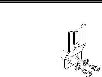
ATTACHING THE
MICROPHONE HOLDER
Follow these steps to attach the microphone holder to your vehicle.
1.Using the holder as a template, mark the position for the mounting screw holes at the desired location.
2.At each marked position, drill a hole slightly smaller than the supplied mounting screw.
Caution: Be careful not to drill into anything behind the mounting surface.
3.Use a Phillips screwdriver to attach the holder to the mounting location with the supplied small self-tapping sheet metal screws and lock-washers.
MOUNTING THE TRANSCEIVER
The most common mounting location for this transceiver is under a vehicle’s dashboard. However, if you plan to use the transceiver as a base station, you can place it on a desk, shelf, or table (see “Using the Transceiver as a Base Station” on Page 13).
If you are mounting the transceiver in a vehicle, choose a location where:
•you can easily reach the transceiver
•wires and cables are clear of the vehicle’s pedals or other moving parts
•the transceiver is not directly in front of heating vents
•all wires and cables can reach their connection points
9

Caution: If you use the transceiver in a vehicle, mount it securely to avoid damage to the transceiver or vehicle, or injury to anyone in the vehicle during sudden starts or stops.
Follow these steps to mount the transceiver.
VOL
OP
SQ
1.Using the mounting bracket as a template, mark the positions for the screw holes on the mounting surface,
2.In each marked location, drill a hole slightly smaller than the supplied self-tapping screws.
Caution: Be care not to drill into objects behind the mounting surface.
3.Using a Phillips screwdriver, attach the mounting bracket to the mounting surface with the supplied mounting screws and flat washers.
4.Attach the transceiver to the mounting bracket using the supplied rubber washers and mounting knobs.
10
CONNECTING AN ANTENNA
You must install an antenna before you can operate the transceiver. There are many different types of antennas suitable for transceiver use. Each has its own benefits, Choose the one best suited to your particular needs. Your local RadioShack store has a wide selection from which to choose.
Note: If you are using the transceiver as a base station, see “Using the Transceiver as a Base Station” on Page 13.
When you install an antenna, keep in mind that, for the best performance, you should mount the antenna vertically as high as possible on the vehicle and away from sources of electrical noise.
Once you choose an antenna, follow it’s mounting instructions. Then route the cable to the transceiver and thread the cable onto the ANT connector on the back of the transceiver.
Cautions:
•Avoid routing the cable next to sharp edges or moving parts, which might damage the cable.
•Do not run the cable next to power cables or other radio antenna cables.
•Do not run the cable through the engine compartment or other areas that produce extreme heat.
To take advantage of your transceiver’s maximum range, adjust the antenna’s standing wave ratio (SWR) using an SWR meter (not supplied, available at your local RadioShack store). Follow the instructions supplied with the SWR meter and antenna to adjust the antenna’s SWR. Values of 2.0:1 are generally acceptable, with readings of 1.5:1 or lower being more desirable.
11
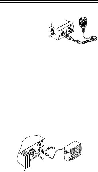
CONNECTING THE MICROPHONE
1. Align the notch of the microphone’s plug and the microphone’s jack, located on the left side of the front panel. Then insert the plug and turn the metal ring clockwise to secure the plug.
2. Slide the microphone onto the microphone holder.
To disconnect the microphone from the transceiver, turn the metal ring counterclockwise to loosen it.
Caution: Always disconnect the microphone by grasping its plug. Never pull on the coiled microphone cable.
USING AN EXTERNAL SPEAKER
To hear your communications better in a noisy environment, you can plug an optional, external speaker into the transceiver. The speaker should have an impedance of 8-ohms and be able to handle 3 to 10 watts of power. The speaker’s cable should have a 1/8-inch (3.5-mm) plug.
To connect the speaker, insert the speaker cable’s plug into EXT. SP on the back of the transceiver. This automatically disconnects the built-in speaker.
12
 Loading...