


QC824

User Manual
QC SERIES
NVRS
QC828 NVR 8 Channels
H.264 NETWORK VIDEO RECORDERS
720P and 1080P Recording Options
POWERHDD1 2 3 4 5 6 7 8 9 10 11 12 13 14 15 16 NET
ESCFNRECSHIFT
ENTER
1
Thank You for Choosing a Q-See Product!
All of our products are backed by a conditional service warranty covering all hardware for 12
months from the date of purchase. Additionally, our products also come with a free exchange
policy that covers all manufacturing defects for one month from the date of purchase.
Permanent upgrading service is provided for the software and is available at www.Q-See.com.
Be certain to make the most of your warranty by completing the registration form online. In
addition to warranty and technical support benefits, you’ll receive notifications of product
updates along with free downloadable firmware updates for your NVR. Register today at
www.Q-See.com!
Please see the back of this manual for exclusions.
About this Manual
This manual is written for the QC800 Series of Network Video Recorders (NVRs) and was
accurate at the time it was completed. However, because of our ongoing effort to constantly
improve our products, and the different capabilities of the models covered in this manual,
additional features and functions may have been added since that time and on-screen
displays may change. We encourage you to visit our website at www.Q-see.com to check for
the latest firmware updates and product announcements.
Your NVR is pre-configured in a way that most users find sufficient to their needs. However,
because we understand that everyone’s individual situation differs and because we are
committed to providing the best value possible, our products contain a full range of features
which may be tailored to custom-fit most situations. It is unlikely that you will need to use all of
the features to meet your security needs, but they are available for when you do.
This manual covers the setup and local operation of the NVR. Instructions for configuring the
NVR for remote access, along with instructions for monitoring the NVR using a computer or
mobile device, are contained within the Remote Monitoring Guide which is included on the
CD that accompanied your NVR and which can also be found on www.Q-See.com/support.
Throughout the manual we have highlighted warnings and other important information that will
assist you in operating your new system in a safe and trouble-free manner. Please take the
time to read and follow all instructions and pay attention to alerts as shown below:
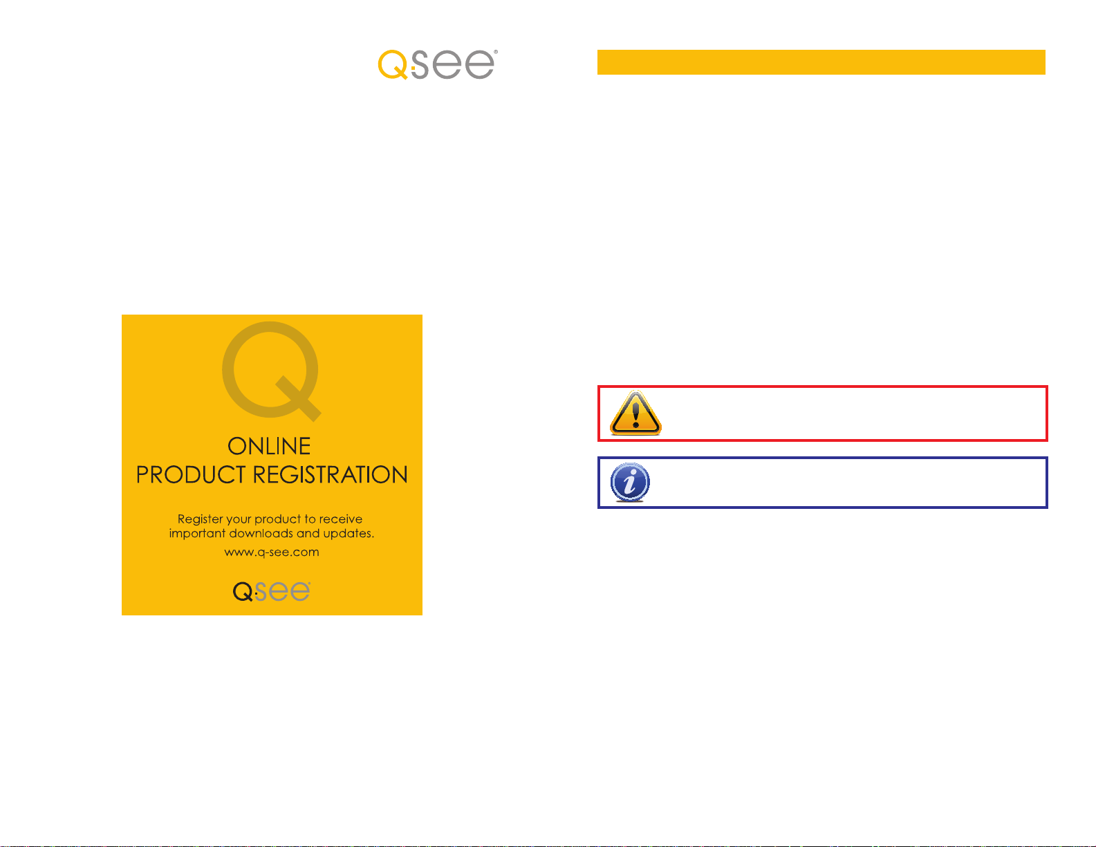
IMPORTANT! Red boxes with this icon indicate warnings. To prevent
possible injury or damage to the product, read all warnings before use.
NOTE! Text in blue boxes with the Information icon offer additional guidance
and explanations about how to make the most out of your system.
© 2011-2013 Q-See. Reproduction in whole or in part without written permission is
prohibited. All rights reserved. This manual and software and hardware described herein, in
whole or in part, may not be reproduced, translated, or reduced to any machine-readable
form without prior written approval.
Trademarks: All brand names and products are trademarks or registered trademarks of their
respective owners.
Q-See is a registered trademark of DPS, Inc.
Disclaimer: The information in this document is subject to change without notice. The
manufacturer makes no representations or warranties, either express or implied, of any kind
with respect to completeness of its contents.
Manufacturer shall not be liable for any damages whatsoever from misuse of this product.
Version 2.6 11/7/13
2 3

TABLE OF CONTENTS
1. INTRODUCTION 7
Features and Specifications 8
2. CONNECTIONS AND CONTROLS 10
2.1 Connections 10
QC804, 808 and 8016 10
QC814 12
QC824 13
QC818 14
QC828 16
QC8116 18
2.2 Mouse Control 20
Virtual Keyboard 21
2.3 Remote Control 22
2.4 IP Cameras 24
Locally Connected Cameras 24
Cameras Connected througha Network 25
Adding and Removing Cameras in Your Display 26
A Note About Resolution and Recording 26
3. BASIC OPERATION 27
3.1 Operation 27
3.2 Live View 27
Navigation Bar 28
Shortcut Video Controls 29
3.3 Login, Logout and Main Menu 30
Login 30
Shortcut Menu 31
Main Menu 32
Shutdown 32
Auto Resume 32
3.4 Recording 33
Manual Recording 33
Camera Settings 34
Schedule 37
Alarm 38
Motion, Video Loss and Camera Masking Detection 39
3.5 Search and Playback 42
Search 44
Playback 46
Digital Zoom 48
Back-Up 49
3.6 Backup 50
4. MENUS 52
4.1 Main Menu 53
4.2 Info Menu 53
HDD Information 53
Log 54
Online Users 55
Remote Device Info 56
Network Resource Info 57
4.3 Setting Menu 58
RS232 60
Alarm 60
Network 60
PTZ 60
Display 61
Default 62
4.5 Remote Device 63
Edit 65
Configuring IP Cameras 65
Adding and Deleting Remote Devices 67
4.6 Advanced 68
HDD Manage 68
Error Alerts 69
Account 70
Auto Maintenance 70
4.7 Backup 71
4.8 Shutdown 71
5. PAN/TILT/ZOOM CAMERAS 72
5.1 Connecting a PTZ Camera 72
5.2 PTZ Control and Setup 73
Setup 73
Control 74
Setting Preset/Patrol/Pattern/Scan 75
Running PTZ Functions 77
6. ALARMS 78
6.1 Alarm Input 78
6.2 Alarm Output 80
6.3 Alarm Setup and Activation 81
7. HARD DISK DRIVE 84
7.1 Installation/Removal 84
(Continued Next Page)
4 5
APPENDIX 86
A.1 Troubleshooting 86
A.2 Specifications 89
Q-SEE PRODUCT WARRANTY 92
Questions or Comments? Contact Us 93
INTRODUCTION
To prevent damage to your Q-See product or injury to yourself or to others, read and
understand the following safety precautions in their entirety before installing or using this
equipment. Keep these safety instructions where all those who use the product will read them.
CHAPTER 1
WARNING! ELECTRIC SHOCK RISK!
nCheck the unit and any accessories included in the package immediately after opening. If
items are missing or damaged, repackage and return to the point of purchase.
n
Use the proper power source. Only use the power adapter supplied with your system. Do
not use this product with a power source that applies more than the specified voltage (100240V AC).
nNever insert anything metallic into the NVR. Inserting anything into the NVR or its case can
be a source of dangerous electric shock.
nDo not operate in dusty areas. Avoid placing the NVR in places that are dusty.
nDo not expose this product to rain or use near water. If this product accidentally gets wet,
unplug it and contact Q-See immediately.
nKeep product surfaces clean and dry. To clean the outside case of the NVR, gently wipe
using a lightly dampened cloth (only use water, do not use solvents).
nDo not operate this NVR without the cover securely in place. Do not attempt to do any
repairs to the NVR yourself. If there are unusual sounds or smells coming from the NVR,
unplug it immediately and contact Q-See technical support. Under no circumstances
should the cover be removed while the device is connected to a power source. You should
only remove the cover to install/replace the hard disk drive (See Chapter 6) or replace the
standard 3v lithium cell battery on the motherboard. These are the only user serviceable
parts. You may need to replace the battery if the internal clock resets itself after a power
outage
nHandle NVR box carefully. If you accidentally drop your NVR on any hard surface, it may
cause a malfunction. If the NVR doesn’t work properly due to physical damage, contact
Q-See for repair or exchange.
nMake sure there is proper air circulation around the unit. This NVR system uses a hard drive
for video storage which generates heat during operation. Do not block air holes located on
the sides of the NVR as they are designed to keep the system cool while running. Install or
place this product in an area where there is ample air circulation.
nProvide proper ventilation. This NVR has a built-in fan that properly cools the processor. Do
not cover or impede this fan.
6 7
FEATURES AND SPECIFICATIONS
Your NVR (Network Video Recorder) contains professional-grade features and flexibility that
allows the do-it-yourselfer to easily setup and maintain a reliable and secure security system
for home and office.
It utilizes a dual-core CPU running an embedded Linux operating system to maintain stable
operation and a popular H.264 compression algorithm to produce high-quality, low bitstream
footage that is easy to manage and efficient to transfer over the internet. It can use various
functions such as record, playback, and monitoring at the same time and produces audio and
video synchronization. This product has advanced network technology and data transmission
functions allowing you to control and monitor your system remotely.
This product offers the following features:
Smartphone Compatible
Access live footage directly from your iPhone, iPad, Android phone and tablet or other
supported mobile device. Your NVR can also be set to e-mail your hand held-device
whenever specific activity occurs, such as motion detection.
Connect to a TV or PC Monitor Easily
This system comes with VGA and HDMI video output ports to allow you to connect to a
computer monitor or HD display for viewing purposes. Some models also include a BNC
video port to allow the use of an analog television as a video display.
Individually Configurable User Controls
Create up to 20 individual user accounts giving specific users access to only certain functions,
cameras and etc.
24/7 Scheduled Recording
Choose which days of the week and hours of the day you want to set your NVR to record or
not record.
Included Mouse and Remote Control
In addition to the front panel button controls, system can also be booted up and shut down
using the included remote control or mouse. Mouse operation function supports intelligent
operation by enabling copy and paste functions.
Dual Video Streams
The NVR will record high definition video directly to its internal hard drive, while streaming a
more compact, lower resolution video feed over the network or Internet for real-time viewing
on a computer or mobile device.
Built-in Power Over Ethernet (POE) Blocks
The POE Block allows you to power and view a number of cameras directly connected to the
NVR without the need for additional power supplies or wiring. Connecting through the POE
allows instantaneous video feed from your cameras.
View Your Video Feed Online with No Additional Service Fees
View your NVR’s live or recorded video footage on any Internet accessible computer with
Internet Explorer, Apple Safari, Mozilla Firefox and Google Chrome (using IE plug-in).
Stay Notified with Customizable Email Alerts
Set your system up to notify you when an event has occurred at the location you are
monitoring. Notification alerts can easily be adjusted to your specifications.
Advanced Motion Detection Activated Recording
Advanced motion detection settings ensure that false alarms are not triggered. The easy to
use motion detect set up screen allows you to mask out certain areas which experience heavy
movement in order to avoid false alarms and avoid unnecessary record triggering.
Multiple Backup Options
A built-in USB port gives you the option of backing up and transferring your video footage
using a flash drive or external USB hard drive. You can also connect to an external CD/
DVD writer to burn your file footage right onto a compact disc or DVD disc. Files can also be
accessed from your NVR system to a remote computer location by logging on remotely.
Storage Function
Encrypted file format to ensure data security and avoid vicious data modification.
Multiple Playback Options and Advanced Search Functions
Supports real-time recording on each channel independently. Search through recorded files
while you are playing live footage, monitoring through a remote location using a supported
internet browsing application and backing up system files. A variety of playback modes
include: slow play, fast play, backward play and frame by frame play.
Network Monitoring
Supports network remote real-time monitoring (available bandwidth permitting) and remote
record search.
Alarm Activation Function
Several relay alarm outputs enable you to pair your system with an on-site alarm system.
Communication Ports
Standard Ethernet port allows you to access the NVR from a network or the Internet.
NOTE! Depending on your point of purchase, your NVR may have the hard
disk drive already installed. If your drive was packaged separately, or if you
wish to upgrade your installed drive up to a 3TB drive, please see Chapter 6
at the back of this manual which covers installing the drive.
8 9
CONNECTIONS AND CONTROLS
2.1 CONNECTIONS
QC804, 808 AND 8016
Front Panel
1 2
QC808 NVR 8 Channels
3 4 65
POWERHDD1 2 3 4 5 6 7 8 9 10 11 12 13 14 15 16 NET
ESCFNRECSHIFT
ENTER
CHAPTER 2
Rear Panel
1 4 85 72 3 6
AUDIO
DC 48V
POE PORTS
VIDEO OUT
OUT
IN
RS232
VGA
NO C
NO C NO C
A91102113124135146157168B
DC 12V
7 8 9 10 11 1312 14
Number Item Function
Channel
1
Status Lights
2 Status Lights
3 IR Sensor Infrared Receiver for Remote Control
Directional
4
Buttons
5 Enter Button
6 Power Button Puts NVR into Standby mode or wakes it up.
Directional
7
Play Buttons
Playback
8
Speed
Frame
9
Playback
10 Shift Button For use in Virtual Keyboard
11 Record Button Begins manual recording on all channels
Function
12
Button
13 Escape Button Exit any menu or current operation
14 USB Port
These lights will illuminate to indicate that a particular channel
is recording.
Net and HDD will illuminate if there are problems with the
network connection or hard drive, respectively. The power
light will illuminate when the NVR is powered up.
Navigate through menus.
Change selections in pull down menus (Up/Down buttons)
Toggle settings (Up/Down buttons)
Viewing Mode: Go To Menu
In Menu: Acts as mouse click
Play back video forwards or backwards. Pressing the same
button a second time will pause the video.
Slow or speed up playback - 1/4 speed to 4x speed.
Move forward or backwards frame-by-frame through video.
Works when video is paused.
Single Channel Viewing Mode: Opens Color Adjustment
Virtual Keyboard: Backspace function
For use with flash drive when backing up or updating
firmware. Not for use with mouse.
10
9
11 12
13
Number Item Function
POE Power
1
Input
2 POE Block
48V power input for the Power Over Ethernet (POE) block.
Powers directly-connected cameras and receives video
images.
3 Video Out BNC Connector to television
4 Audio Out BNC Connector for audio output
5 RS232 Reserved for use by manufacturer.
6 Alarm Input
Connect up to 16 external alarm sensors to this block. The
top row of numbers is for the upper block.
Connect up to 3 external alarms using the Normally Open
(NO) or Closed (C) port
Connect the data cables for a PTZ camera into the ports
labeled A and B to control it. “A” is positive (+) and “B” is
7
PTZ and Alarm
Out
negative (-).
8 Power Switch
Turns NVR on or off. Use Shutdown menu function or front
panel power button before switching off.
9 USB Connect the USB mouse to this port
10 Audio In BNC input for audio feed from microphone
11 Network Ethernet cable connection to network
12
HDMI Video
Out
To connect to an HD display
13 VGA Video Out To connect to a VGA monitor (19” or larger)
14
NVR Power
Input
Connect 12V DC power supply here
14
If the user is logged out, pressing the Enter button will open the Login window. Pressing the
Function button will open the Virtual Keyboard which can be navigated using the directional
buttons. Click Enter to enter a keystroke. Press the Escape button to close the Virtual Key-
Your NVR comes with two power supplies. The 48V is exclusively for use in powering the POE
block while the 12V 5A supply is for the NVR itself. The plugs and receptacles are different to
aid in connecting the proper power supply. Do not force or alter these connectors.
board and then press the Enter button to submit your password.
10 11
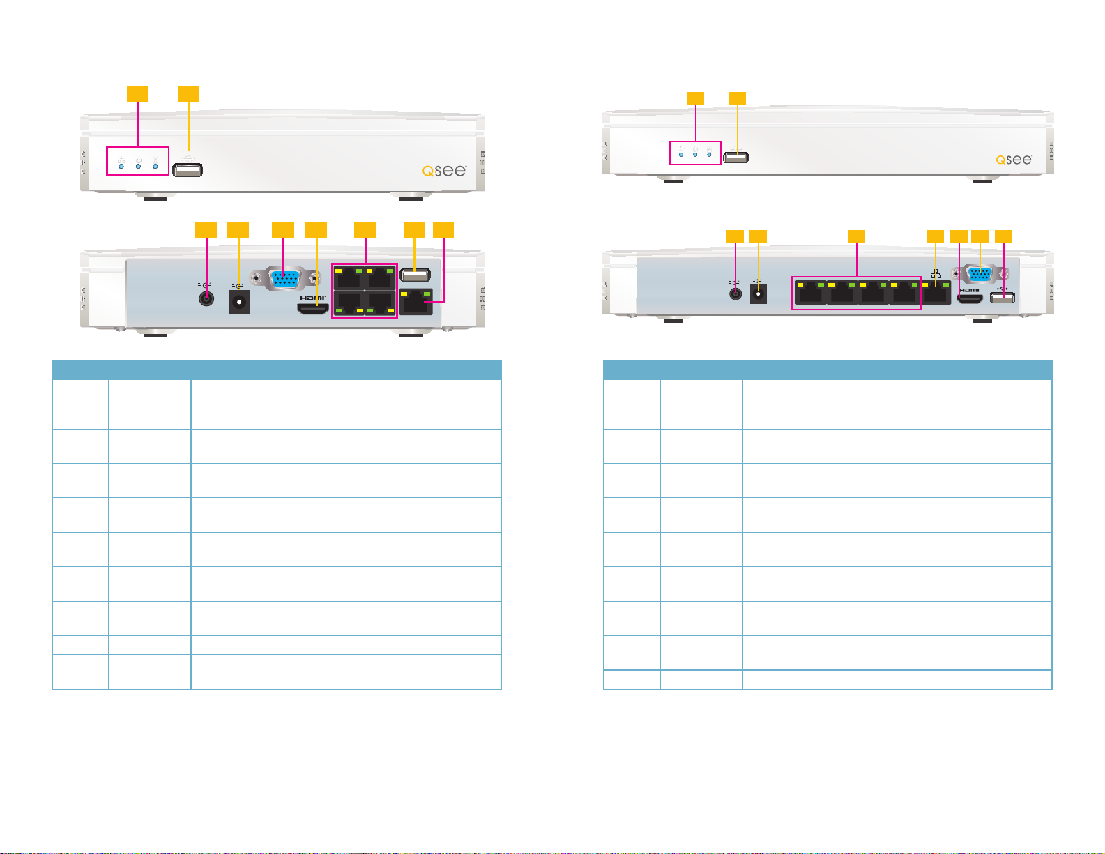
QC814
Front Panel
QC824
Front Panel
1 2
Rear Panel Rear Panel
3
DC 48V
DC 12V
Number Item Function
These show the status of the network connection, power and
1 Status Lights
hard drive respectively. The Network and Power lights will
normally be on. The Hard Drive light will normally be off.
2 USB Port
POE Power
3
Input
NVR Power
4
Input
VGA Video
5
Out
HDMI Video
6
Out
7 POE Block
For use with flash drive when backing up or updating
firmware. Not for use with mouse.
48V power input for the Power Over Ethernet (POE) block.
12V power input for the NVR itself
To connect to a VGA monitor (21.5” or larger)
To connect to an HD display (21.5” or larger)
Powers directly-connected cameras and receives video
images.
8 USB Connect the USB mouse to this port
9 Network
Ethernet cable connection to network. You cannot connect a
camera to this port.
5 7 84 6 9
VGA
Number Item Function
1 Status Lights
2 USB Port
3
4
5 POE Block
6 Network
7
8
9 USB Connect the USB mouse to this port
1 2
POE Power
Input
NVR Power
Input
HDMI Video
Out
VGA Video
Out
3
DC 48V
DC 12V
5 7 94 6 8
VGA
These show the status of the network connection, power and
hard drive respectively. The Network and Power lights will
normally be on. The Hard Drive light will normally be off.
For use with flash drive when backing up or updating
firmware. Not for use with mouse.
48V power input for the Power Over Ethernet (POE) block.
12V power input for the NVR itself
Powers directly-connected cameras and receives video
images.
Ethernet cable connection to network. You cannot connect a
camera to this port.
To connect to an HD display (21.5” or larger)
To connect to a VGA monitor (21.5” or larger)
For full 1080P resolution video preview, you must use a 21.5 inch or larger monitor with
1920x1080 resolution.
Your NVR comes with two power supplies. The 48V is exclusively for use in powering the POE
block while the 12V 5A supply is for the NVR itself. The plugs and receptacles are different to
aid in connecting the proper power supply. Do not force or alter these connectors.
12 13
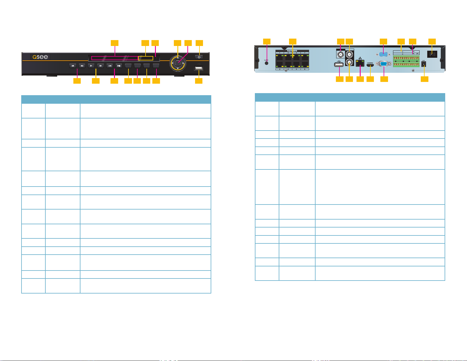
QC818
Front Panel
QC818 NVR 8 Channels
1 2
3 4 65
POWERHDD1 2 3 4 5 6 7 8 9 10 11 12 13 14 15 16 NET
ESCFNRECSHIFT
ENTER
7 8 9 10 11 1312 14
Rear Panel
1 4 85 72 3 6
AUDIO
VIDEO OUT
OUT
DC 48V
IN
10
9
11 12
RS232
VGA
13
NO C
NO C NO C
A91102113124135146157168B
DC 12V
14
Number Item Function
1
Channel
Status Lights
These lights will illuminate to indicate that a particular channel
is recording.
Net and HDD will illuminate if there are problems with the
2 Status Lights
network connection or hard drive, respectively. The power
light will illuminate when the NVR is powered up.
3 IR Sensor Infrared Receiver for Remote Control
Directional
4
Buttons
5 Enter Button
Navigate through menus.
Change selections in pull down menus (Up/Down buttons)
Toggle settings (Up/Down buttons)
Viewing Mode: Go To Menu
In Menu: Acts as mouse click
6 Power Button Puts NVR into Standby mode or wakes it up.
7
8
9
Directional
Play Buttons
Playback
Speed
Frame
Playback
Play back video forwards or backwards. Pressing the same
button a second time will pause the video.
Slow or speed up playback - 1/4 speed to 4x speed.
Move forward or backwards frame-by-frame through video.
Works when video is paused.
10 Shift Button For use in Virtual Keyboard
11 Record Button Begins manual recording on all channels
12
Function
Button
Single Channel Viewing Mode: Opens Color Adjustment
Virtual Keyboard: Backspace function
13 Escape Button Exit any menu or current operation
14 USB Port
For use with flash drive when backing up or updating
firmware. Not for use with mouse.
Number Item Function
POE Power
1
Input
2 POE Block
48V power input for the Power Over Ethernet (POE) block.
Powers directly-connected cameras and receives video
images.
3 Video Out BNC Connector to television
4 Audio Out BNC Connector for audio output
5 RS232 Reserved for use by manufacturer.
6 Alarm Input
Connect up to 16 external alarm sensors to this block. The
top row of numbers is for the upper block.
Connect up to 3 external alarms using the Normally Open
(NO) or Closed (C) port
Connect the data cables for a PTZ camera into the ports
labeled A and B to control it. “A” is positive (+) and “B” is
7
PTZ and Alarm
Out
negative (-).
8 Power Switch
Turns NVR on or off. Use Shutdown menu function or front
panel power button before switching off.
9 USB Connect the USB mouse to this port
10 Audio In BNC input for audio feed from microphone
11 Network Ethernet cable connection to network
12
HDMI Video
Out
To connect to an HD display
13 VGA Video Out To connect to a VGA monitor (19” or larger)
14
NVR Power
Input
Connect 12V DC power supply here
If the user is logged out, pressing the Enter button will open the Login window. Pressing the
Function button will open the Virtual Keyboard which can be navigated using the directional
buttons. Click Enter to enter a keystroke. Press the Escape button to close the Virtual Key-
Your NVR comes with two power supplies. The 48V is exclusively for use in powering the POE
block while the 12V 5A supply is for the NVR itself. The plugs and receptacles are different to
aid in connecting the proper power supply. Do not force or alter these connectors.
board and then press the Enter button to submit your password.
14 15
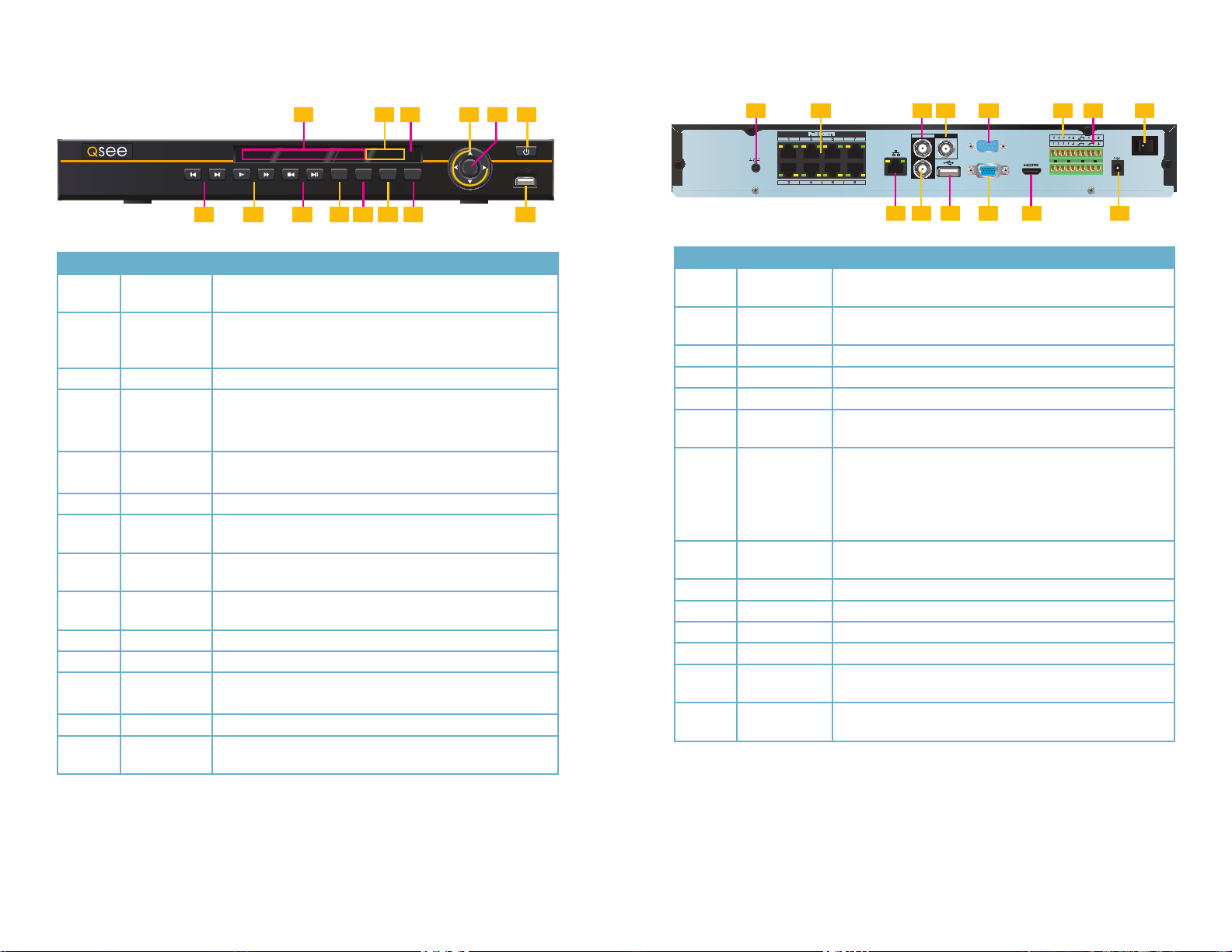
QC828
Front Panel
QC828 NVR 8 Channels
1 2
3 4 65
POWERHDD1 2 3 4 5 6 7 8 9 10 11 12 13 14 15 16 NET
ESCFNRECSHIFT
ENTER
Rear Panel
1 4 85 72 3 6
AUDIO
VIDEO OUT
DC 48V
OUT
IN
RS232
VGA
DC 12V
7 8 9 10 11 1312 14
Number Item Function
Channel
1
Status Lights
2 Status Lights
3 IR Sensor Infrared Receiver for Remote Control
Directional
4
Buttons
5 Enter Button
6 Power Button Puts NVR into Standby mode or wakes it up.
Directional
7
Play Buttons
Playback
8
Speed
Frame
9
Playback
10 Shift Button For use in Virtual Keyboard
11 Record Button Begins manual recording on all channels
Function
12
Button
13 Escape Button Exit any menu or current operation
14 USB Port
These lights will illuminate to indicate that a particular channel
is recording.
Net and HDD will illuminate if there are problems with the
network connection or hard drive, respectively. The power
light will illuminate when the NVR is powered up.
Navigate through menus.
Change selections in pull down menus (Up/Down buttons)
Toggle settings (Up/Down buttons)
Viewing Mode: Go To Menu
In Menu: Acts as mouse click
Play back video forwards or backwards. Pressing the same
button a second time will pause the video.
Slow or speed up playback - 1/4 speed to 4x speed.
Move forward or backwards frame-by-frame through video.
Works when video is paused.
Single Channel Viewing Mode: Opens Color Adjustment
Virtual Keyboard: Backspace function
For use with flash drive when backing up or updating
firmware. Not for use with mouse.
10
9
11 12
13
Number Item Function
POE Power
1
Input
2 POE Block
48V power input for the Power Over Ethernet (POE) block.
Powers directly-connected cameras and receives video
images.
3 Audio Out BNC Connector for audio output
4 Video Out BNC Connector to television
5 RS232 Reserved for use by manufacturer.
6 Alarm Input
Connect up to 8 external alarm sensors to this block. The top
row of numbers is for the upper block.
Connect up to 3 external alarms using the Normally Open
(NO) or Closed (C) port
Connect the data cables for a PTZ camera into the ports
labeled A and B to control it. “A” is positive (+) and “B” is
7
PTZ and Alarm
Out
negative (-).
8 Power Switch
Turns NVR on or off. Use Shutdown menu function or front
panel power button before switching off.
9 Network Ethernet cable connection to network
10 Audio In BNC input for audio feed from microphone
11 USB Connect the USB mouse to this port
12 VGA Video Out To connect to a VGA monitor (19” or larger)
13
14
HDMI Video
Out
NVR Power
Input
To connect to an HD display
Connect 12V DC power supply here
14
If the user is logged out, pressing the Enter button will open the Login window. Pressing the
Function button will open the Virtual Keyboard which can be navigated using the directional
buttons. Click Enter to enter a keystroke. Press the Escape button to close the Virtual Key-
Your NVR comes with two power supplies. The 48V is exclusively for use in powering the POE
block while the 12V 5A supply is for the NVR itself. The plugs and receptacles are different to
aid in connecting the proper power supply. Do not force or alter these connectors.
board and then press the Enter button to submit your password.
16 17
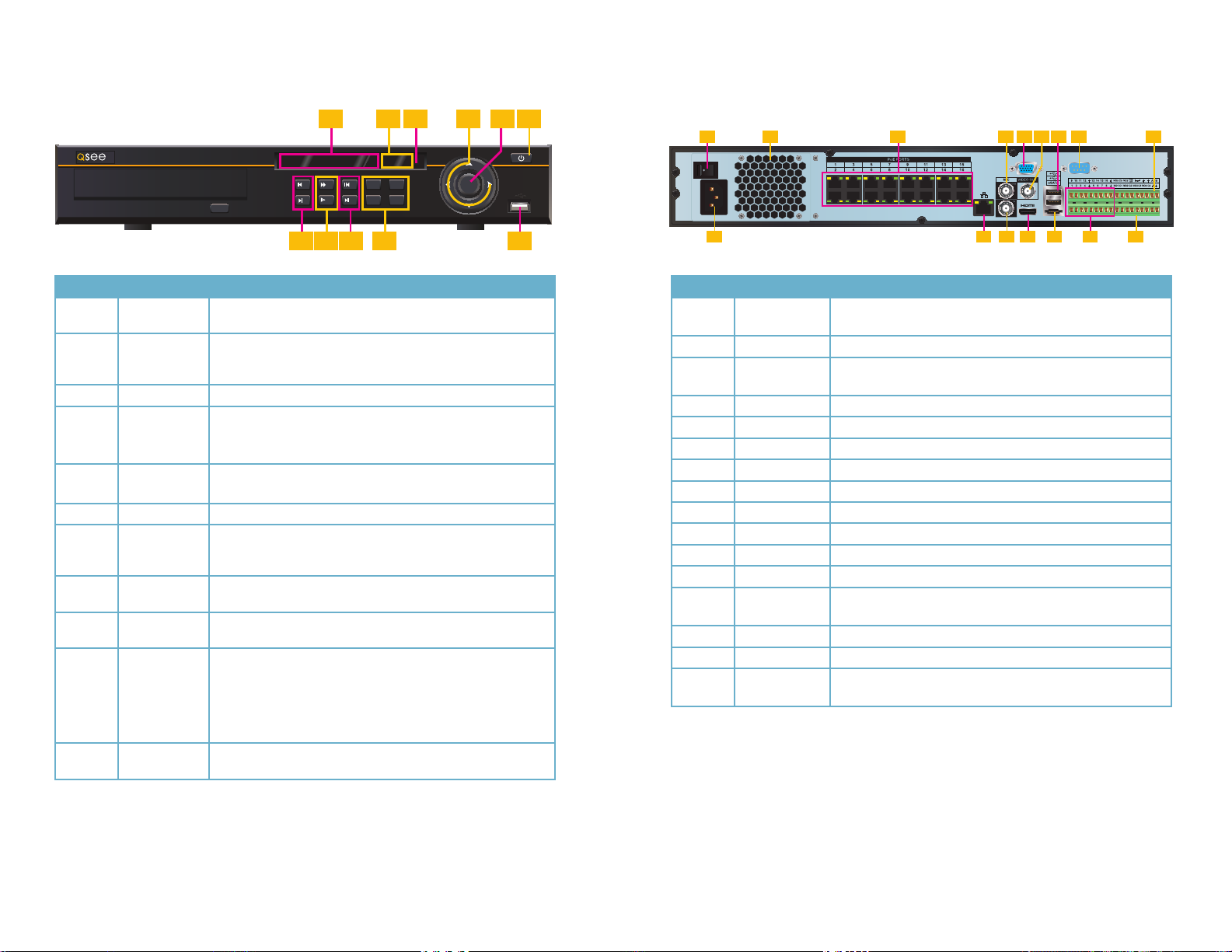
QC8116
Front Panel
Rear Panel
1 2 6
HD
HD NVR 16 Channels QC8116
Number Item Function
1
Channel
Status Lights
These lights will illuminate to indicate that a particular channel
is recording.
Net and HDD will illuminate if there are problems with the
2 Status Lights
network connection or hard drive, respectively. The power
light will illuminate when the NVR is powered up.
3 IR Sensor Infrared Receiver for Remote Control
Directional
4
Buttons
5 Enter Button
Navigate through menus.
Change selections in pull down menus (Up/Down buttons)
Toggle settings (Up/Down buttons)
Viewing Mode: Go To Menu
In Menu: Acts as mouse click
6 Power Button Puts NVR into Standby mode or wakes it up.
Video
7
Playback
Play back video forwards or backwards. Pressing the same
button a second time will pause the video.
Buttons
Playback
8
Speed
Frame
9
Playback
Slow or speed up playback - 1/4 speed to 4x speed.
Move forward or backwards frame-by-frame through video.
Works when video is paused.
Rec - Begins manual recording on all channels
Esc - Exit any menu or current operation
Shift - For use in Virtual Keyboard
Fn - Single Channel Viewing Mode: Opens Color Adjustment
10
Funtion
Buttons
Virtual Keyboard: Backspace function
11 USB Port
For use with flash drive when backing up or updating
firmware. Not for use with mouse.
192103114125136147158 ACT POWER
/9/7/
/0/8/
7 8 10 11
16
STATUS
ESCREC
5
6
FNSHIFT
9
3 4 5
1
2
ENTER
3
4
1 2 6
3 4 8 95 7
RS232
10 12 1411 13 1615
Number Item Function
1 Power Switch
Turns NVR on or off. Use Shutdown menu function or front
panel power button before switching off.
2 Fan Cooling fan exhaust port. This should not be blocked
3 POE Block
Powers up to 16 directly-connected cameras and receives
video images.
4 Audio In BNC input for audio feed from microphone
5 VGA Video Out To connect to a VGA monitor (19” or larger)
6 Video Out BNC Connector to television
7 USB (x2) Use for USB mouse and external USB hard drive.
8 RS232 Reserved for use by manufacturer.
9 RS485 For controlling peripherals using the RS485 standard
10 Power input Attachment point for power cord
11 Network Ethernet cable connection to network
12 Audio Out BNC Connector for audio output
13
HDMI Video
Out
To connect to an HD display
14 eS ATA Connection for external eSATA hard drive for backup
15 Alarm Input Connect up to 16 external alarm sensors to this block.
16 Alarm Out
Connect up to 4 external alarms using the Normally Open
(NO) or Closed (C) port
If the user is logged out, pressing the Enter button will open the Login window. Pressing the
Function button will open the Virtual Keyboard which can be navigated using the directional
buttons. Click Enter to enter a keystroke. Press the Escape button to close the Virtual Key-
board and then press the Enter button to submit your password.
18 19
2.2 MOUSE CONTROL
SYSTEM LOGIN
User Name
Password
admin
Your NVR is mainly controlled through the USB mouse. Some models can also be controlled
through a remote control or by using the buttons on the front panel of the device. We have
found that the majority of our customers prefer to operate their NVRs using the USB mouse
because of its ease of use and flexibility and our manual is set up with this in mind. The remote
control, if included, allows you to perform most of the day-to-day functions from a convenient
distance. It functions as a typical remote control with additional buttons allowing you to
navigate through menus and control functions. Please note that NVRs without an IR Sensor
on the front panel (see your model’s illustration in the previous Connection section) cannot
be controlled via remote control and none will be provided. Also, the sensor must not be
blocked or obstructed in order for the remote to function. We recommend that you configure
your NVR using the mouse controls, reserving the remote control for operations such as live
viewing, file search and playback.
The mouse operates in a manner similar to how it is used on a conventional computer; pointand-click, right-click, double click and so on. How these functions are used is based on the
context of where they are used. Some examples are:
LEFT CLICK: Selecting an item
Opening a menu
Checking a box or motion detection status
Selecting letters, numbers or symbols on the virtual keyboard.
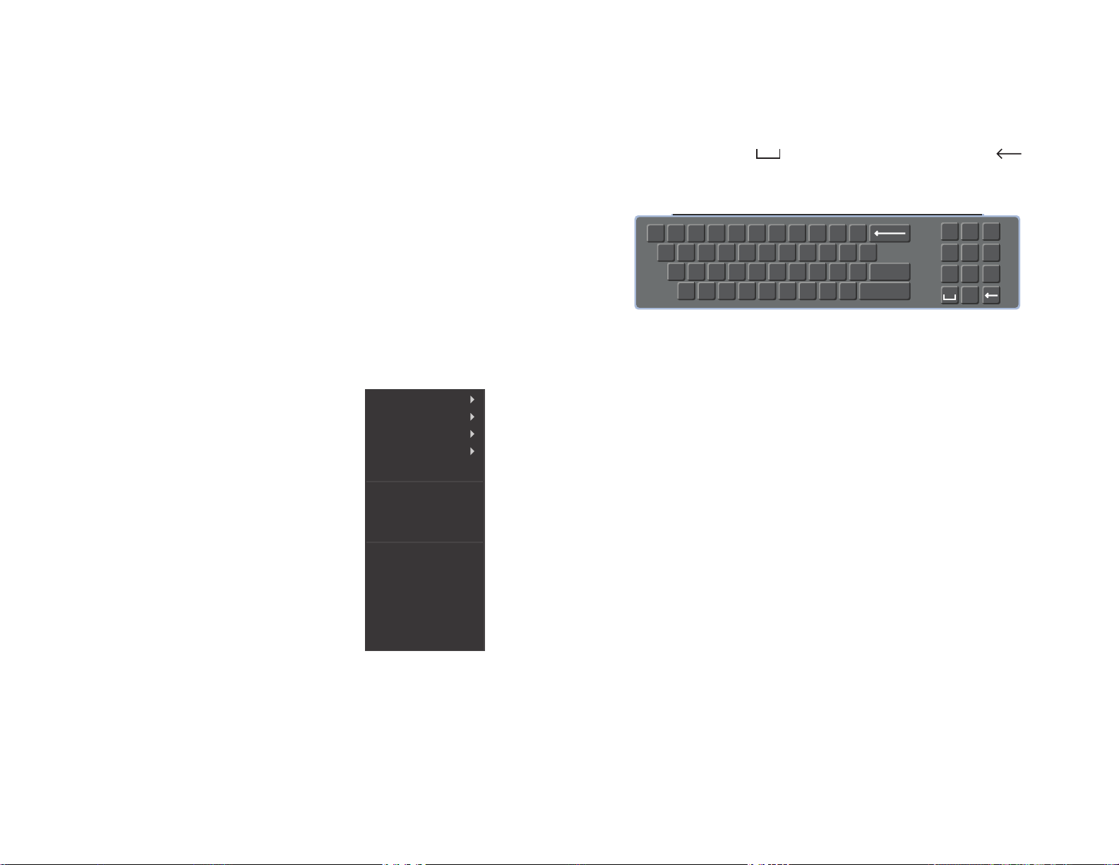
VIRTUAL KEYBOARD
Whenever a menu field requires text - such as a password, new user name, or other setting
- clicking on that field will bring up the virtual keyboard. It operates as regular keyboard using
the point and click function of the mouse to select individual characters. Clicking the shift key
allows access to the upper-case characters.
Spaces are entered using the symbol and characters are deleted with the key.
Clicking Enter or clicking outside of the keyboard will close it.
! ? @ # $ % ^ + * - _
q w e r t y u i o p |
a s d f g h j k l ; Enter
z x c v b n m , .
PICTURE 2-2
Shift
1 2 3
54 6
87 9
0
DOUBLE CLICK:
Selecting a screen to
Selecting an event for
playback
zoom into from multiscreen mode
View 1
View 4
View 8
View 9
View 16
Pan/Tilt/Zoom
RIGHT CLICK Exits any window. Exits
any menu or reopens
previous menu.
Opens Pop-Up
Shortcut Menu. The
options available especially multi-channel
viewing options - will
vary by model
MOUSE WHEEL Page up or page down
Switch items in check box
Increase or decrease numerical value in numerical input box
CLICK-AND-DRAG Select motion detection zone
Select privacy mask zone
Auto Focus
Color Setting
Search
Record Status
Tour Setup
Remote Device
Alarm Output
Main Menu
PICTURE 2-1
20 21
2.3 REMOTE CONTROL
The buttons on the Remote Control operate in the same manner as on a conventional video player
remote. Some buttons have multiple functions depending on which menu is being accessed.
If your DVR cannot use a remote control, none will be provided.
Num. Name Function
1 Power Button Turn on or shut down the NVR before turning it off with the
power switch.
2 Address An additional security feature. You can require the NVR to
ask you to enter the Device Number (found in the General
Settings menu) before being able to access the log-in
screen.
3 Fast Forward Multiple fast forward speeds in Playback mode.
Zoom in when in PTZ mode.
4 Next Record Goes to next video in Playback mode.
Adjust focus when in PTZ mode.
5 Slow Play Multiple slow playback speeds and resumes normal
playback.
Zoom out when in PTZ mode.
6 Play/Pause Will open Playback/Search mode.
Begins playback of selected video or pauses current video.
Adjust Iris (light level) in PTZ mode.
7 Previous Record Goes to previous video in Playback mode.
Adjust focus when in PTZ mode.
8 Reverse/Pause “Rewind” current video or resume normal playback.
Adjust Iris (light level) in PTZ mode.
9 Escape Cancel current function or exit current menu.
10 Enter Select default button. Go to main menu.
11 Multi-view mode Cycle through available multi-screen display modes.
12 Record Opens recording interface. Use directional keys to select
recording mode and channel.
13 Directional Keys Navigate through menus.
Cycle through channels in single- or 8-screen viewing
mode.
Control Playback progress bar in Playback mode
Control PTZ camera and switch menus in PTZ mode.
14 Function Opens volume control.
Switches PTZ control menu
Use with Directional keys to set up Motion Detection
15 0-9 Keys Use in similar manner to phone keypad to enter password,
etc.
Push number to select desired channel for viewing.
1 2
3
4
5
6
7
8
9 12
10
13
11
14
15
PICTURE 2-3
NOTE! The QC814 and QC824 cannot be operated using a remote control
and your package will not include one.
22 23
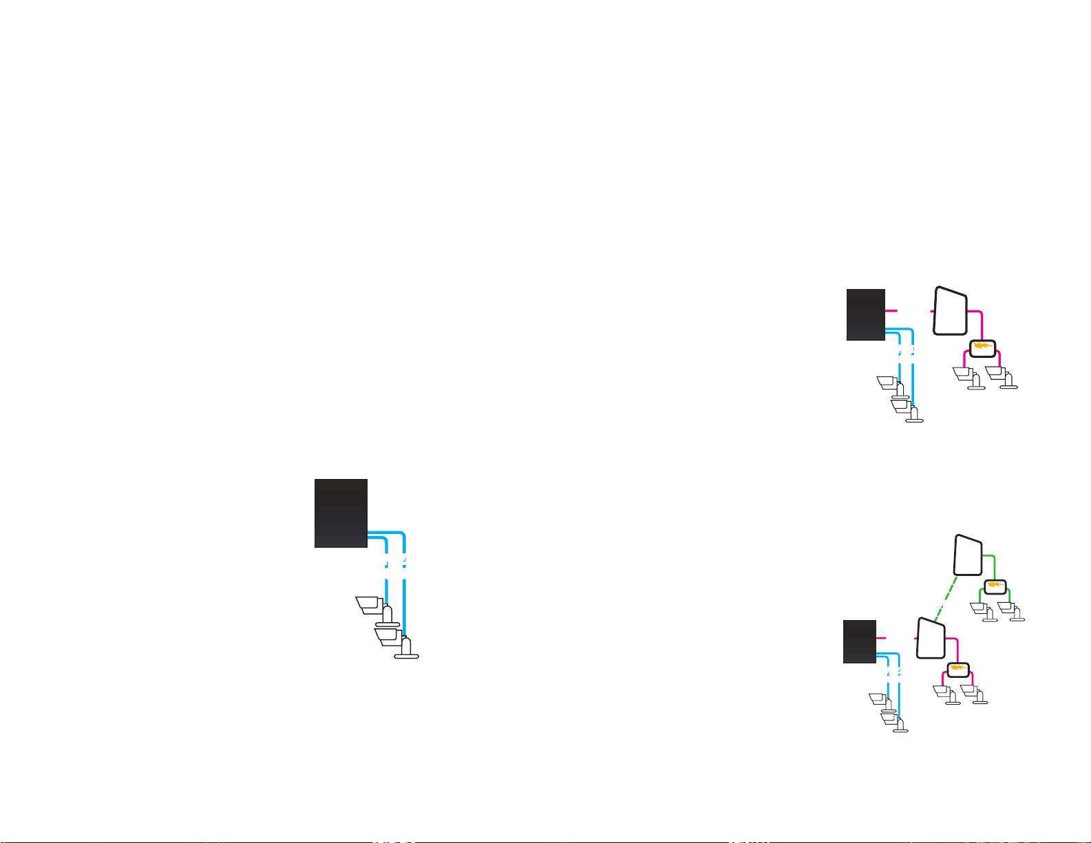
2.4 IP CAMERAS
NVR
POE
Block
POE
Block
Network
Network
Port
POE
Router
NVR
POE
Block
POE
Block
POE
Router/
Modem
POE
Router/
Modem
NetworkNetwork
Port
Internet
Internet
NVR
POE
Block
POE
Block
POE
Router/
Modem
POE
Router/
Modem
NetworkNetwork
Port
Internet
Internet
Internet Protocol (IP) or Network cameras differ from conventional video cameras in that each
is a stand-alone device with a built-in processor of its own. This allows it communicate directly
with the NVR by using standard internet protocols whether it is connected directly to the
NVR or over a network or even the Internet. It is for this reason that the NVR treats them as
peripheral or remote devices with the NVR serving as the interface and recording system.
Your NVR features an industry-exclusive built-in Power Over Ethernet (POE) block that allows
you to connect up to four IP cameras directly to it up to 200 feet away using RJ-45 (Ethernet)
cables without the need to purchase a separate power block or to locate the cameras near
power outlets. The Ethernet cable will both power the camera and deliver the video signal to
your system.
The NVR will assign cameras to channels in the order they were connected. Therefore, if
you have a particular sequence that you want for your cameras, it is recommended that you
connect them one at a time.
Cameras connecting to your system over a network (local or Internet) will also ultimately
connect through your network’s router and their signal will be received by the NVR through its
Network port. These cameras will need to be powered on their side of the network.
Whenever possible, it is best to use a continuous length of cable rather than multiple short
segments as each intervening connection could result in a small loss of power and signal.
As of this writing, this NVR supports IP cameras made by: Dahua, Arecont Vision, Axis,
Canon, Dynacolor, Panasonic, Samsung, Sanyo, Sony and Onvif.
LOCALLY CONNECTED CAMERAS
For the purposes of these instructions, “locally connected cameras” are those that are
plugged directly into the NVR’s POE ports.
Using the Power Over Ethernet Block
Your NVR’s POE block will power up to four
cameras while receiving their video signals.
This is the primary and preferred method to
connect cameras to your NVR. This feature
cannot be expanded through use of a
network switch. These ports are also not to
be used to connect the NVR to a network
router. When an IP camera is connected to
the NVR through the POE port, it will receive
power immediately, but there may be a
delay of up to a minute before the camera’s
signal appears on the screen as the system
establishes connectivity.
NVR
POE
POE
Block
Block
PICTURE 2-4
If you are unsure, and if your camera has infrared LEDs, you may cup your hand over the lens
area to activate the infrared night vision mode. You will see a faint red glow from the LEDs
confirming that the camera has power.
CAMERAS CONNECTED THROUGHA NETWORK
There are two types of networks – local (LAN or Intranet) and Internet (or WAN). Cameras can
be accessed by the NVR over both types.
Local Networks
For cameras positioned too far away to reasonably run a network cable directly to the NVR,
you can connect it to the same network as the NVR and the system will be able to access
and use them.
Ultimately, each camera will have to connect
to the same router that the NVR is connected
to. They will need to be connected to a
power source on their side of the network preferably a POE - as the POE block on the
NVR itself is unable to provide power through
the network.
Alternately, if your NVR was bundled with
cameras, they may include a power input
as additional power option. You will need to
acquire a power adapter that matches the
ratings listed on the camera itself if you are
not connecting them to a POE.
The NVR will connect to these cameras
through the same cable that it uses to
communicate with the network.
Connections Over the Internet
A third connection option is via the Internet.
This method is more complicated, but it
allows the user to view cameras that are
located in a completely different building –
or region – from the NVR itself. In essence,
your NVR will be remotely monitoring those
cameras. As such, the user will need to
forward ports using the IP Tool software
included on the Manuals and Software
CD to obtain the IP address for any camera
that will be accessed over the Internet. Full
instructions are included in the manual for
that software.
NVR
NVR
Network
Network
Port
POE
POE
Block
Block
PICTURE 2-5
Router/
NetworkNetwork
Modem
Port
POE
POE
Block
Block
PICTURE 2-6
Router
Internet
Internet
Router/
Modem
POE
POE
POE
24 25
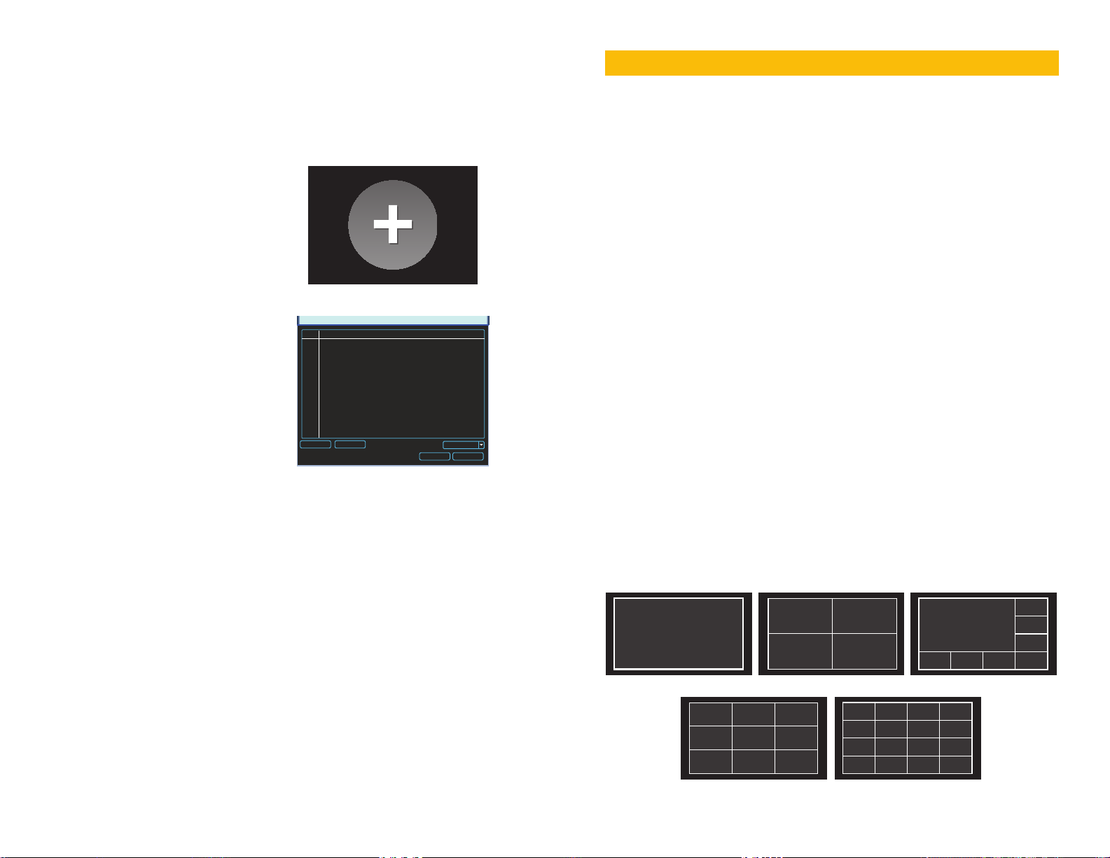
ADDING AND REMOVING CAMERAS IN YOUR DISPLAY
As stated earlier, your NVR will automatically show video from cameras connected to it directly
through the POE Block as they are connected - assigning them to channels sequentially
regardless of which port is used to connect them. Cameras sharing the network with the NVR
will not automatically connect. There are two ways to connect them - through the use of the
Add Camera icon in the Live View window and the Remote Device window located in the
Main Menu. The latter method will be covered in detail in Section 4.5.
Add Camera
Moving the cursor to the center of any empty
BASIC OPERATION
This chapter is intended to get your system operational in a baseline format now that you’ve
connected your system and turned it on after following the instructions on the Quick Start
Poster that came with your system. This chapter combines information and instructions on
several submenus and settings but may not mention all of the functions or options available
in a given menu. For many users, these basic operating instructions may be all they need to
operate their security system. But, because this system offers many more features, the next
chapters will cover additional and more advanced operations in greater detail.
CHAPTER 3
channel will reveal the Add Camera icon
shown in Picture 2-7. Clicking on this will
open a window listing available cameras.
As stated on page 3 of this manual, certain screen shots may not exactly match the images
that appear on your screen. You may see a reference to a feature, menu or setting that is
not available on your system. This is due to our continued upgrading of the NVR’s firmware,
along with not all models sharing the same features. We welcome requests as well as user
feedback as part of our ongoing effort to improve our products. These may be made through
our Knowledge Base - which is where you will also find questions to the vast majority of your
questions - at www.Q-See.com/Support.
3.1 OPERATION
This NVR can be controlled through the USB mouse, the remote control or by using the
buttons on the front of the device. For the purposes of this manual, instructions will be given
for using the mouse.
Clicking on IP Search will refresh this list.
Simply click on the desired camera from the
list and it will become the camera for that
channel. Please note that it is possible to load
PICTURE 2-7
2 IP Address Port Device ID Manufacturer Type
1 10.1.1.65 1 YZC2OC061966 Private IPC-HFW210
2 10.1.1.67 2 YZCAU192012 Private IPC-HFW321
REMOTE DEVICE
a camera which is already in use by another
channel. In which case, you will have two
identical channels.
IP Search Manual Add
None
Filter
Add Cancel
In operation, the mouse functions in the same manner as one would use a mouse attached
to a computer; point, click, right-click, and etcetera. In fields where data needs to be entered,
clicking on the field will bring up a virtual keyboard. (See Section 2.3 Mouse Control)
PICTURE 2-8
A NOTE ABOUT RESOLUTION AND RECORDING
IP cameras are available from Q-See in the two common high definition standards - 720P
and 1080P. These resolutions differ in the number of pixels (individual dots that make up the
image) available. The more pixels in an image, the larger, more clearer it will be. Cameras with
720P resolution will produce video 1280 pixels wide by 720 pixels high while that from 1080P
cameras will measure 1920 pixels by 1080 pixels.
3.2 LIVE VIEW
Live View is the default mode for the NVR. It will display the video feeds from up to four, eight
or 16 cameras depending on model. You do not need to be logged into the NVR to view
or change the channel(s) on the screen. The actual number of channels displayed depends
on the number of cameras you own. You can view a single channel in full-screen mode or
multiple channels simultaneously in a variety of layouts.
Of course, the larger the video image, the larger the video file size and the more processing
power that is required to handle the video. For this reason, you may decide to have a 1080P
camera record at a lower resolution to save drive space using the Camera Settings menu
(see Section 3.4).
While all Q-See NVRs are designed to work with both 720P and 1080P cameras, certain
considerations may affect the recording rate which is expressed in terms of Frames Per
Single Screen 4 Screens 8 Screens
Second (FPS). The human eye sees 30FPS as “real time” with lower frame rates being
increasingly more “jerky”. Cameras connected directly through the POE will have smoother
video than those connecting over the Internet simply due to network transfer rates.
Additionally, certain models such as the QC814 and QC818 are optimized for 720P cameras.
While they can process the larger video from 1080P cameras, they will do so at the lower
frame rate of 15FPS. Individual users may also decide to lower the recording frame rate of
a camera to save disk space, or to improve the frame rate from another camera, such as a
remote camera.
9 Screens 16 Screens
PICTURE 3-1
26 27
Clicking on any one screen in multi-view mode will bring that screen to full-screen single-view
mode. The exception is in eight-view where clicking on one of the smaller displays will move it
to the larger display. You can also drag channels to a different position on the screen with the
displaced channel relocating to the position of the one that was moved.
In addition to selecting the viewing mode
from the Shortcut Menu using the mouse,
you can also cycle through the modes using
the up and down arrows on the remote or
the front of the NVR. The left and right arrows
on both the remote and NVR front panel will
cycle through which channels are displayed.
In Live View, along with the channel(s), you will see the system date and time displayed along
with the name and icons indicating the status of each channel. Setting the system date and
time and changing the channel names is covered in Section 4.3 under the Settings menu.
Recording
Motion
detected
View 1
View 4
View 8
View 9
View 16
PICTURE 3-2
Video
loss
NAVIGATION BAR
Left-clicking on the screen in Live View mode will open the Navigation Bar allowing you
shortcut access to select menus and functions. It also serves as an easy-to-view status bar
showing the current situation with alerts, network, and drives.
PICTURE 3-3
Opens
Main
Menu
Opens
Search
Menu
Startup
Wizard
Minimize/
Maximize
Bar
Alarm
Status
Opens
Tour
Setup
Window
Screen
Display
Mode
Network
Status/
Opens
Network
Window
PTZ
Controls
Manage
Hard
Drive
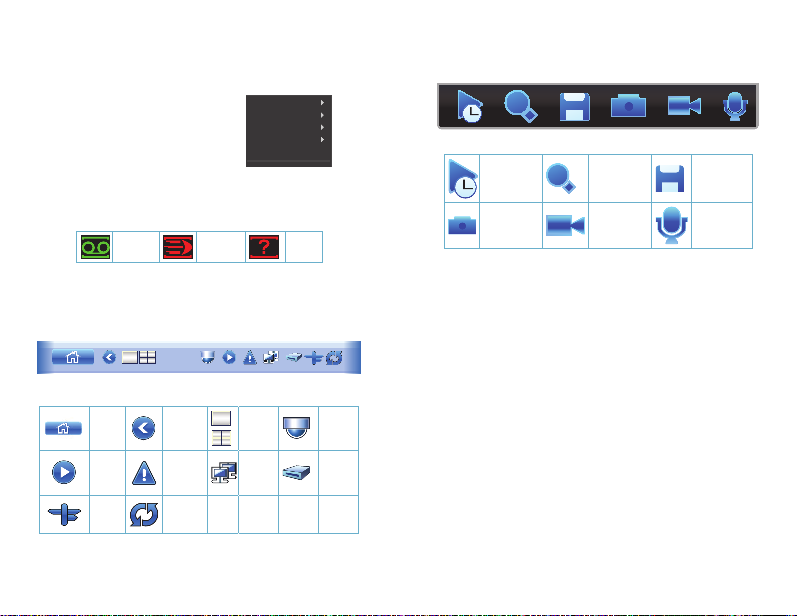
SHORTCUT VIDEO CONTROLS
When the mouse cursor is in the top-center portion of a channel with a live video stream, a
set of shortcut controls will appear. These allow you to perform quick playback and backup
functions, digitally zoom in and add another camera.
PICTURE 3-4
Realtime
Playback
Snapshot
(not available
on all models)
Clicking the Realtime Playback icon will cause the window to play back the most recent
video clip recorded by that camera. The duration of this clip is set in the General Settings
menu.
Click the Digital Zoom icon and then select an area of interest within that channel’s video
feed to enlarge the area. Right-click with the mouse to exit the zoom.
Quick Backup allows you to save the current live video to a USB drive inserted into the front
USB port. If no drive is present, you will receive an error message.
Snapshot allows you to take still images which will be saved onto the hard drive. You can
search for these using the same Search and Playback window used to search for video.
See Section 3.5 for full instructions.
Use Add Remote Device to replace the current camera with another camera - or QC DVR -
from your list of connected cameras shown in the Remote Device menu. You cannot add a
camera that is already being displayed using this tool.
If you have a speaker and microphone located near your camera and you have a microphone
located at your DVR, clicking on the Two-Way Talk icon will allow you to talk anyone within
the same area as the camera. The icon will be green while this feature is active. Unclick it to
hear any responses. You can set the number of pictures taken with each click in the General
Settings menu (see Section 4.3).
You can close the controls either by either right-clicking or by moving the mouse out of the
area.
Digital Zoom Quick Backup
Add Remote
Device
Two-Way
Talk
The icons on the navigation bar will also alert you to issues with the status of your drive,
network connection and alarms with red icons when a situation arises.
28 29
 Loading...