


_VTOP
1 +
14 -
B2_P
11 U11:3
EL2257C 
4
B2_N
IX2
DR2
B3_P
1 +
14 -
U14:3 |
11 |
|
|
|
|
|
|
|
|
EL2257C |
|
|
||
|
|
|||
|
4 |
|
|
|
|
|
|
|
|
|
|
|
|
|
|
|
|
|
|
|
|
|
|
|
IX3
DR3
3 |
|
7 |
|
E |
EL2257C |
+ |
|
13 |
|
|
|
|
|
|
|
C |
U11:1 |
8 |
- |
2 |
|
|
|
|
|
|
|
|
|
D |
|
|
|
G |
|
|
|
S |
|
3 |
|
7 |
|
E |
EL2257C |
+ |
|
13 |
|
|
|
|
|
|
|
C |
U14:1 |
8 |
- |
2 |
|
|
|
|
|
|
|
|
|
D |
|
|
|
G |
|
|
|
S |
|
5 |
|
|
|
|
E |
EL2257C |
|||
9 |
||||
|
|
|||
C |
|
U11:2 |
||
6 |
|
|
||
|
|
|
||
|
|
|
|
|
D
G
S
This connects to chassis gnd at the rear panel.
_SPK
_BOP
1  2
2
_SPK_GND
5 |
|
|
|
|
E |
EL2257C |
|||
9 |
||||
|
|
|||
C |
|
U14:2 |
||
6 |
|
|
||
|
|
|
||
|
|
|
|
|
D
G
S
EL2257C |
5 |
+ |
7 |
EL2257C |
3 |
+ |
1 |
|
9 |
E |
|
|
13 |
|
E |
|
|
U12:2 |
|
|
U12:1 |
|
||||
|
|
8 |
|
14 |
||||
|
C |
- |
|
|
C |
- |
||
|
6 |
|
|
|
|
2 |
|
|
D |
|
|
|
D |
|
|
|
|
G |
|
|
|
G |
|
|
|
|
S |
|
|
|
S |
|
|
|
|
1 |
_BGND |
2 |
|
5 |
|
7 |
|
3 |
|
1 |
EL2257C |
E |
+ |
EL2257C |
E |
+ |
||
9 |
|
|
13 |
|
|
||
|
|
|
|
|
|
||
U13:2 |
C - |
8 |
U13:1 |
C - |
14 |
||
|
6 |
|
|
|
2 |
|
|
D |
|
|
|
D |
|
|
|
G |
|
|
|
G |
|
|
|
S |
|
|
|
S |
|
|
|
_VBOT
PM_REF
QTY ITEM NO. |
PART NO. |
DESCRIPTION |
4 11
B1_P
U12:3
EL2257C
B1_N
IX1
DR1
B3_P
11 |
U13:3 |
|
EL2257C
4
IX4
DR4
VENDOR

|
|
IX1 |
DR1 |
|
|
DR3 |
IX3 |
IX2 |
DR2 |
|
|
DR4 |
IX4 |
|
|
|
VBOT |
VTOP |
BGND |
BOP |
|
|
VBOT |
VTOP |
BGND |
BOP |
|
|
PM_REF |
|
|
|
|
|
|
|
|
|
|
|
|
25V- |
|
|
|
|
|
|
|
|
|
|
|
|
|
C129 |
|
|
|
|
|
|
|
|
|
|
|
|
|
22u |
|
|
|
|
|
|
|
|
|
|
|
|
|
|
_BOP |
_BGND |
|
|
|
|
|
|
|
|
|
|
|
|
|
|
|
14 U21:1 |
1 |
|
|
|
|
8 |
U21:2 7 |
|
|
|
|
|
|
13 |
2 |
|
|
|
|
9 |
6 |
|
|
|
|
|
|
|
3 |
|
|
|
|
11 |
|
|
|
C125 |
22u-25V |
|
|
|
4 |
|
|
|
|
12 |
|
|
|
|
|
CA3054M96 |
|
|
|
|
CA3054M96 |
|
|
||||
|
|
|
|
|
|
|
|
|
|
|
|
||
|
|
|
|
U21:3 |
|
|
|
|
|
|
|
|
|
|
|
|
|
5 |
|
|
|
|
|
|
|
|
|
|
|
|
|
CA3054M96 |
|
|
|
|
|
|
|
|
|
|
|
|
CW |
|
|
|
|
|
|
|
|
|
|
|
|
|
|
W |
|
|
|
|
|
|
|
|
|
|
|
|
CCW |
|
|
|
|
|
|
|
|
|
|
|
|
|
|
|
|
DN_DRV |
|
|
UP_DRV |
|
|
|
|
_VBOT |
|
|
|
|
|
|
|
|
|
|
|
|
|
C126 |
|
|
|
|
|
|
|
|
|
|
|
|
|
22u-25V |
|
HOT |
|
|
|
|
|
|
|
|
|
|
|
|
B3_N |
|
|
|
|
|
|
|
|
|
|
|
|
|
|
|
|
I_MON |
|
|
|
Gain = 1/37.5 |
|
|
|
|
|
||
_V200 |
|
|
|
|
|
|
|
|
3 |
+ |
|
|
|
|
_BOP |
|
1 |
5 |
|
|
MUTE |
||
|
|
|
|
+ |
|
||
|
2 |
- |
5V=187V |
6 |
|
7 |
|
|
|
|
|
|
|
||
|
|
|
|
|
- |
|
|
_N_STEP |
|
|
|
|
|
|
|
|
|
|
|
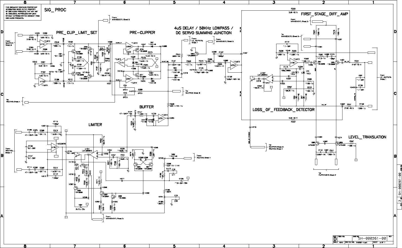
Positive = Clip |
|
|
|
|
|
|
|
|
2 |
VP |
|
|
|
|
|
- |
|
|
|
|
|
|
|
1 |
|
|
|
Values shown preclip a fixed |
|
|
|
+ |
3 |
|
|
|
|
|
|
|
VN |
|
|
5 volts below the rails up to |
|
|
|
|
|
|
|
15 amps of output current. |
|
|
|
|
|
|
|
After that, preclip advances |
|
|
|
|
|
|
|
120 mV per ampere output, |
|
|
|
2 |
|
|
|
for 12v preclip at 70 amps. |
|
|
|
|
- |
With values shown, the effective |
|
6 |
- |
|
|
|
|
1 |
|
|
7 |
3 |
|
step switch time delay is 4us |
|||
|
|
|
|
|
|||
5 |
|
|
|
+ |
flat out to 50 KHz. |
||
+ |
|
|
|
|
|
|
|
|
|
|
|
|
|
|
CLAMP_SIG |
|
|
|
|
|
|
0.84 atten. |
|
CLIP |
|
|
|
|
|
|
|
|
|
|
|
|
|
3 |
+ |
|
|
|
|
|
|
|
1 |
|
|
|
|
|
|
2 |
- |
VP
PRE_LIM
-POL- |
|
+15V_ |
|
|
|
|
|
5 |
+ |
8 |
-POL- |
|
|
|
|
Gain = 1.67 |
|
7 |
|
|
|
|
|
|
|
|
|
|
|
|
|
6 |
- |
4 |
|
|
11 |
|
3 |
|
|
|
|
+ |
|||
|
|
|
|
|
|
||
|
|
|
7 |
5 |
|
|
2 |
|
|
-15V_ |
|
|
1 |
- |
4 |
|
|
8 |
|
6 |
|||
|
|
|
|
|
CLIP_FEED |
||
|
|
|
|
|
|
|
REREF
Limiter is shown in "fast clip-tracking"mode. To convert to a slow attack/release limiter, open the 3 places shown shorted with lines, and make the connection shown by the arrow line.
VP
VP
VP
VN
GAIN_RETARD
|
|
|
|
|
DIFF_AMP_BIAS |
|
|
|
|
|
|
|
P_ISENSE |
|
|
|
|
|
|
|
N_ISENSE |
|
|
-POL- |
|
|
|
|
|
_SPK_GND |
|
|
|
|
|
|
|
|
|
|
|
|
|
3 |
+ |
|
|
5 |
+ |
|
|
|
1 |
|
_BOP |
|
7 |
|
|
2 |
- |
|
-POL- |
6 |
- |
|
|
|
+POL+ |
|
|
|
|
|
+ |
14 |
|
|
|
|
10 |
12 |
|
15 |
|
|
|
|
9 |
16 |
- |
13 |
|
|
|
|
|
|
|
|
|
|
|
|
|
|
VP |
|
|
|
|
|
|
|
|
|
Closed loop gain |
|
|
|
|
|
|
|
=37.5 or 31.5 dB |
|
|
|
|
|
|
VN |
|
|
|
|
|
|
|
|
|
|
_SPK |
|
LOSS_OF_FEEDBACK |
|
|
|
|
|
|
|
|
|
|
|
DN DRV |
UP DRV |
VN |
|
|
|
|
|
|
||
|
|
|
|
|
|
|
|
|
|
8 |
|
|
|
|
|
|
|
|
SHED_V |
|
|
7 |
SHED_V |
|
|
|
|
|
|
|
|
|
|
||
|
|
|
|
|
|
|
|
|
|
6 |
PWR_GND |
|
|
|
|
|
|
|
|
|
|
|
|
|
|
|
|
|
|
|
|
|
|
5 |
|
|
|
|
|
|
|
|
+15V |
|
|
|
|
|
|
|
|
|
|
|
PSENABLE_A |
|
|
4 |
PSENABLE_A |
|
|
|
|
|
|
|
|
|
|
||
STANDBY |
1 |
|
|
|
|
|
|
I_SET |
3 |
I_SET |
|
|
|
|
|
|
|
|
|
||||
MSP_VMON |
2 |
MSP_VMON |
|
|
|
|
|
|
|
2 |
PWR_GND |
|
|
|
|
|
|
|
|
|
|||
D_GND |
3 |
|
|
|
|
|
PSENABLE_K |
|
|
1 |
PSENABLE_K |
|
|
|
|
|
|
|
|
|
|||
MSP_IMON |
4 |
MSP_IMON |
|
|
|
|
|
|
|
|
|
|
|
|
|
|
|
|
|
|
|
||
|
|
5 |
280 KHz LPF |
|
|
|
|
|
|
|
|
MODE_FLAG |
|
|
|
|
|
|
|
|
|
|
|
|
|
|
|
|
|
|
|
|
|
|
|
CLIP_ |
6 |
|
|
|
|
|
|
|
|
|
|
|
|
|
|
|
|
|
|
|
|
|
|
SIG_GND |
7 |
-POL- |
2 |
- |
1 |
|
|
|
|
|
|
|
|
|
|
|
|
|
|
|
|||
|
|
|
|
|
|
|
|
|
|
||
|
|
|
3 |
+ |
+POL+ |
|
|
|
|
|
|
|
|
|
|
|
|
|
|
|
|
|
|
CH_IN_N |
8 |
|
|
|
|
|
|
|
|
|
|
|
+POL+ |
|
|
|
|
|
|
|
|
|
|
|
|
|
|
|
C88 |
|
|
|
|
|
|
|
9 |
|
|
|
|
47-10NP-10% |
+POL+ |
1 |
|
J6:1 |
|
|
|
|
|
|
|
|
|||||
CH_IN_P |
|
|
|
|
|
|
|
|
|
|
POT_TOP |
REREF |
10 |
|
|
|
-POL- |
|
|
|
|
2 |
J6:2 |
|
|
|
|
|
|
|
|
|
|
REREF |
|
|
11 |
|
|
|
|
|
-POL- |
3 |
J6:3 |
|
|
POST_POT_N |
|
|
|
|
|
|
POST_POT_N |
||||
|
|
|
|
|
|
|
|
|
|
||
POST_POT_P |
12 |
|
|
|
|
|
|
|
|
4 |
J6:4 |
|
|
|
|
|
|
|
|
|
|
POST_POT_P |
|
PRE_LIM |
13 |
|
|
|
|
|
|
5 |
|
J6:5 |
|
|
|
|
|
|
|
|
|
|
|
SIG_GND |
|
+15V_ |
14 |
B1_P |
|
|
|
STANDBY_LED |
|
|
|
6 |
J6:6 |
|
|
|
|
|
|
|
|
STANDBY_LED |
|||
SMPS_V |
15 |
SMPS_ON |
|
|
|
|
|
7 |
|
J6:7 |
|
|
|
|
|
|
|
|
|
|
SIG_GND |
||
-15V_ |
16 |
B1_N |
|
|
|
|
VP |
|
|
8 |
J6:8 |
|
|
|
|
|
|
|
|
VP |
|||
|
|
|
PRE_LIM |
|
|
|
|
|
|
|
|
|
C63 |
C68 |
|
|
|
|
|
9 |
|
J6:9 |
|
|
22u-25V |
22u-25V |
|
|
|
|
VN |
|
|
|
VN |
|
|
|
|
|
|
|
|
|
|
||
|
|
|
|
|
|
|
|
|
|
|
|
|
|
|
REREF |
|
|
|
|
|
|
|
J6:10 |
|
|
|
|
|
|
|
|
|
|
10 |
|
|
|
|
|
|
|
|
+15V |
|
|
|
+15V |
|
|
|
|
PROTECT |
|
|
|
|
|
J6:11 |
|
|
|
|
|
|
|
|
|
11 |
|
||
|
|
|
|
|
|
|
V_MON |
|
|
|
V_MON |
|
|
|
|
|
LOSS_OF_FEEDBACK |
CLIP |
|
|
|
|
J6:12 |
|
|
|
|
|
|
|
|
|
|
12 |
|
|
|
|
|
|
|
|
|
|
|
|
PROTECT |
|
|
|
|
|
|
|
|
13 |
|
J6:13 |
|
|
|
|
|
|
|
|
|
|
|
|
PWR_GND |
|
|
|
|
|
|
|
|
|
|
14 |
J6:14 |
|
|
|
|
|
|
|
CLIP_FEED |
|
|
|
CLIP_FEED |
|
|
|
|
|
|
|
|
15 |
|
J6:15 |
|
|
|
|
|
|
|
|
|
|
|
|
CLIP |
|
|
|
|
|
|
|
|
|
|
16 |
J6:16 |
|
|
|
|
|
|
|
|
|
|
|
PWR_GND |

|
|
I_SET |
|
|
|
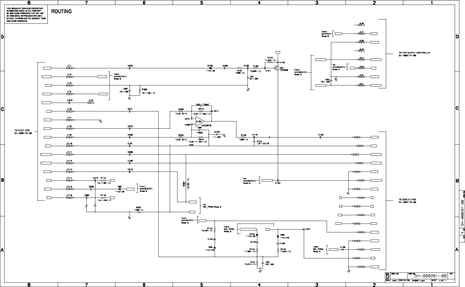
Nominal I_SET = 3ma to 5ma. |
|
|
|
Amp is fully on at I_SET>1ma. |
|
|
|
Above 3ma fan is unaccellerated. |
|
|
|
From 3ma to 1ma speed rises. |
|
|
|
Below 1ma fan speed reduces |
|
|
|
back linearily to normal speed. |
|
_V50 |
|
|
|
1 |
|
|
|
2 |
|
|
|
3 |
|
|
|
4 |
22u-25V |
C55 |
|
FAN_N |
|||
Fan idles at 10V up |
|
|
|
to 60C. From 60C to |
|
|
|
80C fan ramps from |
|
|
|
10V to 24V. At 85C |
|
|
|
fan V = 28V MAX. |
|
|
|
(Note that SMPS can |
|
|
|
also speed fan up.) |
|
|
|
|
|
B3_N |
|
_N_STEP |
|
|
|
5V = 100 deg C. |
|
|
|
+ |
3 |
|
|
1 |
|
|
|
- |
2 |
|
|
HOT=250uA |
|
|
|
@ 80 deg C. |
|
|
|
VP |
|
|
|
HOT |
|
|
|
U1 |
The "HOT" threshold is 80C |
||
2.5V-1% |
|||
Cutback begins at 100C and |
|||
|
|||
|
full shutdown happens at 110C. |
||
|
(+/- 3 degrees) |
||
VP
SMPS_ON
C117 22u-25V
600ms delay to enable audio. 200ms delay to disable audio.
+ 5
7
- 6
SNAPPER PTC
Current gain: 22,460. 3.0 mA total set curent
results in 68A peak output. Minumum at full cut-back is 250 uA or 5.6A output.
PROTECT
VP
DIFF_AMP_BIAS
MUTE |
|
STANDBY_LED |
|
|
D |
|
G |
PSENABLE_A |
|
|
|
|
|
S |
|
|
_BOP |
|
|
PSENABLE_K |
VN
_BGND
VN
_BOP
GAIN_RETARD |
6 |
- |
7
+ 5
Gain = 1/37.5
_SPK_GND
V_MON
2 |
1 |
VP |
|
3 |
|
-POL-
MSP_VMON
|
|
|
+ |
5 |
P_ISENSE |
|
|
|
7 |
|
|
|
|
|
- |
6 |
|
- |
6 |
- |
2 |
|
|
7 |
|
1 |
|
|
|
+ |
5 |
+ |
3 |
|
N_ISENSE |
Total Gain = 16.85dB
VN
I_MON
MSP_IMON
 Loading...