


CXD Amplifier
Quick Start Guide
EXPLANATION OF TERMS AND SYMBOLS
The term “WARNING!” indicates instructions regarding personal safety. If the instructions are not followed the result may be bodily injury or death.
The term “CAUTION!” indicates instructions regarding possible damage to physical equipment. If these instructions are not followed, it may result in damage to the equipment that may not be covered under the warranty.
The term “IMPORTANT!” indicates instructions or information that are vital to the successful completion of the procedure.
The term "NOTE" is used to indicate additional useful information.
The intent of the lightning flash with arrowhead symbol in a triangle is to alert the user to the presence of un-insulated "dangerous" voltage within the product's enclosure that may be of sufficient magnitude to constitute a risk of electric shock to humans.
The intent of the exclamation point within an equilateral triangle is to alert the user to the presence of important safety, and operating and maintenance instructions in this manual.
NOTE: This Quick Start Guide is based on the basic configuration as the amplifier comes from the factory. Four separate inputs, and four separate outputs. For detailed instructions for custom configurations refer to the CXD User Guide (TD-000367).
Rack-Mount the Amplifier
1. Secure the amplifier in the rack with eight screws (not supplied), four in front, four in back.
— Figure 1 —
TD-000350-00-B
*TD-000350-00*
1

Connections
Inputs
1.Wire the audio line-level source to up to four Euro-style connectors (supplied). You may use either balanced inputs (Figure 2) or unbalanced inputs (Figure 3).
2.Plug the connectors into the appropriate receptacles (Routable Inputs 1, 2, 3, 4) Figure 4.
3.Connect the IEC power cord to the AC receptacle on the rear of the amplifier. (Figure 5)
|
Balanced |
|
|
|
|
|
|
|
|
|
Unbalanced |
|||||||||
|
|
|
|
|
|
|
|
|
|
|
|
|
|
|
|
|
|
|
|
|
|
|
|
|
|
|
|
|
|
|
|
|
|
|
|
|
|
|
|
|
|
|
|
|
|
|
|
|
|
|
|
|
|
|
|
|
|
|
|
|
|
|
|
|
|
|
|
|
|
|
|
|
|
|
|
|
|
|
|
|
|
|
|
|
|
|
|
|
|
|
|
|
|
|
|
|
|
|
|
|
|
|
|
|
|
|
|
|
|
|
|
|
|
|
|
|
|
|
|
|
|
|
|
|
|
|
|
|
|
|
|
|
|
|
|
|
|
|
|
|
|
|
|
|
|
|
|
— |
+ |
+ — |
— Figure 2 — |
— Figure 3 — |
GPIO
ROUTABLE INPUTS |
|
|
|
1 |
2 |
3 |
4 |
HEARTBEAT |
GPIO |


 GPIO
GPIO
— Figure 5 —
— Figure 4 —
WARNING!: Do not turn the amplifier on at this time.
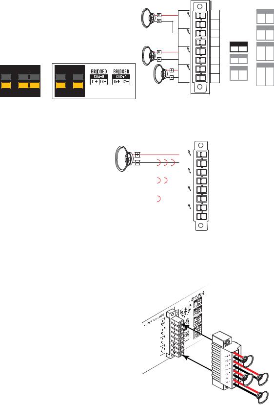
Outputs
When the output configuration of the amplifier changes, the Outputs to the loudspeakers change accordingly. Use the diagrams shown in Figure 6 thru Figure 8 as a reference for wiring the loudspeakers. After connecting the outputs to the loudspeakers, you may turn the amplifier on.
Separate Channels (A B C D)
For Four Separate Loudspeakers
Use four 2-wire cables, connect to:
•T1+/T2- (Loudspeaker 1)
•T3+/T4- (Loudspeaker 2)
•T5+/T6- (Loudspeaker 3)
•T7+/T8- (Loudspeaker 4)
|
|
|
|
OUTPUTS TO SPEAKERS |
|
|
PARALLEL CHANNEL |
|||
|
|
|
|
|
|
|
COMBINING APPLICATIONS |
|||
|
|
|
|
+ |
T1 |
SETTINGS CAN BE |
CH AB |
|||
|
|
|
|
T1+ |
T2- |
|||||
|
|
|
|
CONFIGURED FOR |
||||||
|
|
|
|
CH A |
T2 |
70V, 100V AND |
T3+ |
T4- |
||
|
|
|
|
- |
200V DIRECT |
CH CD |
||||
|
|
|
|
+ |
T3 |
OUTPUT. |
T5+ |
T6- |
||
|
|
|
|
BRIDGED |
T7+ |
T8- |
||||
|
|
|
|
CH B |
T4 |
|
|
|||
|
|
|
|
- |
CH A+B |
CH ABC |
||||
|
|
|
|
+ |
T5 |
T1+ |
T3- |
T1+ |
T2- |
|
|
|
|
|
CH C+D |
T3+ |
T4- |
||||
|
|
|
|
CH C |
T6 |
T5+ |
T6- |
|||
|
|
|
|
- |
T5+ |
T7- |
CH ABCD |
|||
A |
B |
C |
D |
+ |
T7 |
CH AB+CD |
||||
T1+ |
T2- |
|||||||||
|
|
|
|
T1+ |
T5- |
|||||
8.0 |
8.0 |
8.0 |
8.0 |
CH D |
|
T3+ |
T4- |
|||
|
|
|
|
- |
T8 |
T3+ |
T7- |
T5+ |
T6- |
|
625 625 625 625 |
|
|
|
|
T7+ |
T8- |
||||
625 625 625 625 |
|
|
|
|
|
|
||||
— Figure 6 —
2
Bridged (A+B) and Separate (C |
D ) Channels |
|
|
|
|
|
|
|
|||
For A+B (Bridged) One Loudspeaker |
|
OUTPUTS TO SPEAKERS |
|
|
PARALLEL CHANNEL |
||||||
|
|
|
COMBINING APPLICATIONS |
||||||||
Use one 2-wire cable connect to: |
|
|
+ |
T1 |
SETTINGS CAN BE |
CH AB |
|||||
|
|
T1+ |
T2- |
||||||||
• T1+/T3- |
|
|
|
|
CONFIGURED FOR |
||||||
|
|
|
|
CH A |
T2 |
70V, 100V AND |
T3+ |
T4- |
|||
For C & D (Separate) Two Loudspeakers |
- |
200V DIRECT |
CH CD |
||||||||
+ |
T3 |
OUTPUT. |
T5+ |
T6- |
|||||||
Use two 2-wire cables connect to: |
|
|
|
|
|||||||
|
|
BRIDGED |
T7+ |
T8- |
|||||||
|
|
CH B |
T4 |
|
|
||||||
• T5+/T6for CH C |
|
|
|
|
- |
CH A+B |
CH ABC |
||||
• T7+/T8for CH D |
|
|
|
|
+ |
T5 |
T1+ |
T3- |
T1+ |
T2- |
|
|
|
|
|
CH C+D |
T3+ |
T4- |
|||||
|
|
|
|
|
CH C |
T6 |
T5+ |
T6- |
|||
|
|
|
|
|
- |
T5+ |
T7- |
CH ABCD |
|||
A+B |
C |
D |
A+B |
C+D |
+ |
T7 |
CH AB+CD |
||||
T1+ |
T2- |
||||||||||
T1+ |
T5- |
||||||||||
|
|
|
|
|
CH D |
T8 |
T3+ |
T4- |
|||
8.0 |
8.0 |
8.0 |
8.0 |
8.0 |
- |
T3+ |
T7- |
T5+ |
T6- |
||
1250 |
625 |
625 |
1250 |
1250 |
|
|
|
|
T7+ |
T8- |
|
|
|
|
|
|
|
||||||
1250 |
625 |
625 |
1250 |
1250 |
— Figure 7 —
Parallel Channels (ABCD)
For One Loudspeaker
Full power to one loudspeaker
Use one 2-wire cable, connect to:
• T1+/T2-
•Jumper T1, T3, T5, T7
•Jumper T2, T4, T6, T8
For Multiple Loudspeakers
Full power for multiple loudspeakers in parallel
Use up to four 2-wire cables, connect to: |
|
|
|
• T1+/T2- |
|
|
|
• T3+/T4- |
|
A B C D |
|
• T5+/T6- |
|
8.0 |
|
• T7+/T8- |
|
|
|
|
2500 |
|
|
|
2500 |
|
|
|
|
|
|
OUTPUTS TO SPEAKERS |
|
|
|
|
|
PARALLEL CHANNEL |
||||||||||
|
|
|
|
|||||||||||||
|
|
|
|
|
|
|
|
|
|
|
|
|
COMBINING APPLICATIONS |
|||
|
|
|
|
|
|
|
|
|
|
|
|
|
|
CH AB |
|
|
|
|
|
|
|
|
+ |
|
|
T1 |
SETTINGS CAN BE |
|
|||||
|
|
|
|
|
|
|
|
T1+ |
T2- |
|
||||||
|
|
|
|
|
|
CONFIGURED FOR |
|
|||||||||
|
|
|
|
|
|
CH A |
|
|
70V, 100V AND |
T3+ |
T4- |
|
||||
|
|
|
|
|
|
- |
|
|
T2 |
|
200V DIRECT |
|
|
|
||
|
|
|
|
|
|
CH CD |
|
|||||||||
|
|
|
|
|
|
+ |
|
|
T3 |
|
OUTPUT. |
T5+ |
T6- |
|
||
|
|
|
|
|
|
|
|
|
|
|
|
|
||||
|
|
|
|
|
|
|
|
|
|
|
T7+ |
T8- |
|
|||
|
|
|
|
|
|
CH B |
|
|
|
BRIDGED |
|
|
|
|||
|
|
|
|
|
|
- |
|
|
T4 |
|
CH A+B |
|
CH ABC |
|
||
|
|
|
|
|
|
+ |
|
|
T5 |
|
T1+ |
T3- |
|
T1+ |
T2- |
|
|
|
|
|
|
|
|
|
|
|
|
|
T3+ |
T4- |
|
||
|
|
|
|
|
|
CH C |
|
|
|
CH |
C+D |
|
T5+ |
T6- |
|
|
|
|
|
|
|
|
|
||||||||||
|
|
|
|
|
|
|
|
|
|
|
|
|
||||
|
|
|
|
|
- |
|
|
T6 |
|
T5+ |
T7- |
|
|
|
|
|
|
|
|
|
|
|
|
|
|
|
|
|
|||||
|
|
|
|
|
|
+ |
|
|
T7 |
|
CH AB+CD |
|
CH ABCD |
|
||
|
|
|
|
|
|
|
|
T1+ |
T2- |
|
||||||
|
|
|
|
|
|
|
|
|
|
|
|
|
|
|
||
|
|
|
|
|
|
CH D |
|
|
|
T1+ |
T5- |
|
T3+ |
T4- |
|
|
|
|
|
|
|
|
|
||||||||||
|
|
|
|
|
|
- |
|
|
T8 |
|
T3+ |
T7- |
|
T5+ |
T6- |
|
|
|
|
|
|
|
|
|
|
|
|
|
|
||||
|
|
|
|
|
|
|
|
|
|
|
|
|
|
T7+ |
T8- |
|
|
|
|
|
|
|
|
|
|
|
|
|
|
|
|
||
|
|
|
|
|
|
|
|
|
|
|
|
|
|
|
|
|
T1+, T3+, T5+, and T7+ are electrically the same point
T2-, T4-, T6-, and T8are electrically the same point
— Figure 8 —
Connect the Loudspeakers
1. Connect the loudspeaker wiring to the 8-pin Euro-style connector as needed for your amplifier's configuration.
2. Install the female 8-pin Euro-style connector onto the male connector on the rear of the amplifier as shown in Figure 9.
3. Use a Phillips screwdriver to secure the connector.
— Figure 9 —
3
 Loading...