


1675 MacArthur Blvd., Costa Mesa, CA, 92626 USA
Main Number (714) 754-6175 Sales & Marketing (714) 957-7100 or toll free (USA only) (800) 854-4079 Customer Service(714) 957-7150 or toll free (USA only) (800) 772-2834
Cinema Mid-High Loudspeaker System User Manual
MH-1075C 10” (254mm) mid, 3.0” (75mm) compression driver
Introduction
The MH-1075C “mid-high pack” provides the mid and high frequency components of three-way screen channel loudspeaker systems for high performance cinema applications. They were designed to operate with and be directly mounted on QSC’s cinema low-frequency enclosures.
Mid frequencies are reproduced with a 10” (254mm) high-efficiency, phase-ring loaded driver mounted on a custom designed cinema horn. The high-frequency driver is a large format, 3.0” (75mm) titanium diaphragm compression driver mounted on a custom high-frequency cinema horn. The high frequency horn is a low-distortion waveguide providing highly articulate dialogue without coloration associated with conventional horn loudspeakers. Both horns feature broad horizontal and vertical coverage angles to ensure coverage of every seat in the auditorium. The driver assemblies are mounted on an adjustable pan and tilt bracket that has an integral aiming sight, simplifying installation.
The MH-1075C loudspeaker includes a driver protection and crossover network to assure reliable operation. DC blocking capacitors protect against DC or low-frequency signals that could damage an unprotected driver. Power limiter circuitry protects the driver from over-powering and an 18dB/octave crossover seamlessly blends the high and mid frequency elements. Outboard processing is required to form the crossover between the LF and MH loudspeakers.
Bi-amp or tri-amp operation is possible using a selector switch mounted on the connections panel. The bi-amp setting provides a passive crossover network between mid and high drivers. Separate amplifiers and an active crossover are required for the low frequency channel and the mid-high channel. Tri-amp setting disables the internal mid-high crossover and each driver is driven independently by its own amplifier and active crossover; one for the low, one for the mid, and one for the high frequencies.
The MH-1075C components come pre-assembled to reduce field assembly time. Three bolts are all that are required to secure the mid-high assembly to the top of a QSC low-frequency enclosure.
Install in accordance with QSC Audio Product’s instructions and a licensed, professional engineer. Only use attachments, mounts, accessories, or brackets specified by QSC Audio Products, LLC Refer all servicing to qualified personnel. Servicing is required when the apparatus has been damaged in any way.
WARNING! Before placing, installing, rigging, or suspending any speaker product, inspect all hardware, suspension, cabinets, transducers, brackets and associated equipment for damage. Any missing, corroded, deformed or non-load rated component could significantly reduce the strength of the installation, placement, or array. Any such condition severely reduces the safety of the installation and should be immediately corrected. Use only hardware which is rated for the loading conditions of the installation and any possible short-term unexpected overloading. Never exceed the rating of the hardware or equipment. Consult a licensed, professional engineer when any doubt or questions arise regarding a physical equipment installation.
EN
30” (762 mm)
ES
FR
DE
CH
39” (991 mm)
20” (508 mm) 

*TD-000352-00*
TD-000352-00-A
© Copyright 2012, QSC Audio Products, LLC QSC® is a registered trademark of QSC Audio Products, LLC “QSC” and the QSC logo are registered with the U.S. Patent and Trademark Office

Mounting
Attaching to Low Frequency Enclosure
The mid-high loudspeaker assembly attaches to the top of the QSC low frequency cabinet with three M8 bolts, 20mm long, with lock washers. This hardware ships installed on the low frequency cabinet. We recommend the use of serviceable thread locking compound when installing the bolts to prevent loosening due to vibration. Do not fully tighten the mounting hardware before aiming (see below).
Aiming
EN
Aim the horn in the horizontal plane (pan) before tightening the attachment hardware. Adjust the vertical tilt with the mid-high vertical adjustment bracket. The mid-high assembly is equipped with an aiming sight to assist in achieving desired coverage quickly and easily. For typical applications, the aim point should be the center seat in the back row of the auditorium. If the cinema screen has already been installed, a flashlight placed at the desired aiming point can be seen through the screen perforations in a darkened auditorium.
Where the sight holes are located: |
How to use the sights: |
Aim point:
Settings
BI-AMP / TRI-AMP Operating Mode Selection
Set the operating mode selector switch to BI-AMP or TRI-AMP, depending on your application setup.
BI-AMP-When set to BI-AMP, the MH-1075C accepts mid-high frequency signals on one set of inputs and uses an internal crossover network between the midand high-frequency drivers. The signal applied to the mid-high loudspeaker assembly must not contain low-frequency content (below 200 Hz).
TRI-AMP- When set to TRI-AMP, the MH-1075C accepts separate midand high-frequency signals on two sets of inputs. The internal crossover network is bypassed and only the protective circuitry for the H.F. driver remains. Each of the driver’s signals must have the appropriate signal processing before operating.
Do not connect amplifiers directly to the driver inputs! Always use the input terminal strip.
2

Connections
INPUT Terminals
The MH-1075C has barrier strip screw terminals that accept up to #10 AWG (6mm2) stranded loudspeaker wire. Observe proper polarity. Use the largest wire size and shortest wire length for the application.
OUTPUT Terminals
The OUTPUT terminals are factory-connected to the drivers. These terminals should ONLY be connected to their respective driver. Do not connect signals to these terminals as all protection and equalization circuitry will be bypassed.
NOTE! Maintain proper loudspeaker connection polarity throughout the entire system for maximum performance. Do not apply full range signal to the MH-1075C! There is a mid-high passive crossover for bi-amp mode only. There is no crossover
connected when operating in tri-amp mode. A protection network is always active. All required signal processing must be done before the signal is applied to the loudspeaker. Do not connect any signal to the upper sets of OUTPUT terminals.
EN
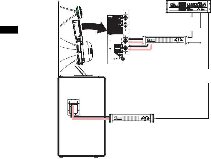
BI-AMP mode connections- Ensure the mode switch is set to BI-AMP, connect the input to the MH-1075C to the lower set of input terminals marked “BI-AMP + -”.
BI-AMP Mode- one amplifier |
MH-1075C |
channel is used for the low |
|
frequency cabinet and one |
|
amplifier channel for the |
|
mid-high assembly. |
|
The MH-1075C mode switch |
|
is set to BI-AMP. Active |
|
crossovers are used before |
|
amplification. The mid-high |
|
assembly provides a passive |
|
crossover between the mid |
|
and high frequency drivers. |
|
DCM |
|
|
|
|
|
|
|
|
|
|
|
|
|
|
|
|
|
|
|
|
|
|
|
|
|
|
|
|
|
|
|
|
|
|
|
|
|
|
|
|
|
|
|
|
|
|
|
|
|
|
|
|
|
|
|
|
|
|
|
|
Mid-High |
|
|
|||
|
|
|
|
|
|
|
|
|
|
|
|
|
|
|
|
Program |
|
|
|||
|
|
|
|
|
|
|
|
|
|
|
|
|
|
|
|
|
|
|
|
|
|
|
|
|
|
|
|
|
|
|
|
|
|
|
|
|
|
|
|
|
|
|
|
|
|
|
|
|
|
|
|
|
|
|
|
|
|
|
|
|
|
|
|
Low |
|
|
|
|
|
|
DCA |
|
|
|
|
|
|
|
Frequency |
||||||||
|
|
|
|
|
|
|
|
|
|
||||||||||||
|
|
|
|
|
|
|
|
|
|
|
|
Program |
|||||||||
|
|
|
|
|
|
|
|
|
|
|
|
|
|
|
|
|
|
|
|||
|
|
|
|
|
|
|
|
|
|
|
|
|
|
|
|
|
|
|
|
|
|
|
|
|
|
|
|
|
|
|
|
|
|
|
|
|
|
|
|
|
|
|
|
|
|
|
|
|
|
|
|
|
|
|
|
|
|
|
|
|
|
|
|
|
|
CH2 CH1
LF-Series Cabinet
3
Connections (continued)
TRI-AMP mode connections- When the mode switch is set to TRI-AMP, connect the high frequency signal to the terminals marked “INPUT HI + -” and the mid frequency signal to the terminals marked “INPUT MID + -”.
|
TRI-AMP Modeone |
MH-1075C |
|
DCM |
|
amplifier channel is |
|
||
|
|
|
|
|
|
used for the low |
|
|
|
|
frequency cabinet, one |
|
|
|
|
amplifier channel for |
|
|
High |
|
the mids, and one |
|
|
|
|
|
|
Frequency |
|
|
amplifier channel for |
|
|
|
EN |
|
|
Program |
|
the high frequencies. |
|
|
||
|
|
Mid |
||
|
The MH-1075C mode |
|
DCA |
Frequency |
|
switch is set to |
|
|
Program |
|
TRI-AMP, bypassing |
|
|
|
|
the internal mid-high |
|
|
|
|
passive crossover. |
|
|
|
|
Active or passive |
|
|
|
|
crossovers are used |
|
|
|
|
before amplification. |
|
|
|
|
Power limiter and DC |
|
|
Low |
|
blocking remain active. |
|
|
|
|
|
|
Frequency |
|
|
|
|
|
|
|
|
|
|
Program |
|
|
LF-Series Cabinet |
|
|
|
|
|
DCA |
|
4

MH-1075C Specifications (subject to change without notice)
Freq. Range |
180 - 15k (-6dB, full space) |
Nominal Coverage |
90° horizontal X +20 to -30° vertical (50° total, adjustable mount provides for vertical plane adjustments. |
|
The horizontal plane can be adjusted by altering mounting position on the low frequency enclosure before |
|
tightening bolts. |
DI: |
9 dB (400 to 16k Hertz average) |
|
Q: |
8 (400 to 16k Hertz average) |
|
Max. Output: |
[Tri-amp mode] |
Mid Freq. 135.5 dB SPL calculated peak, 1m, full space |
|
[Tri-amp mode] |
High Freq. 133 dB SPL calculated peak, 1m, full space |
|
[Bi-amp mode] 135.5 dB SPL calculated peak, 1m ,full space |
|
Impedance: |
[Bi-amp mode] 8 ohms nominal |
|
Maximum Input Power |
[Tri-amp mode] Mid Freq. 275 W (AES method, 2 hrs.) |
|
|
[Tri-amp mode] High Freq. 80 W (AES method, 2 hrs.) |
|
|
[Bi-amp mode] 250 W (IEC method, 8 hrs.) |
|
Sensitivity |
[Tri-amp mode] |
Mid Freq. 105 dB SPL, 1 watt, 1 meter |
|
[Tri-amp mode] |
High Freq. 108 dB SPL, 1 watt, 1 meter |
|
[Bi-amp mode] 105 dB SPL, 1 watt, 1 meter |
|
EN
Crossover Frequencies |
[Tri-amp mode] 250 Hertz or higher, 24dB/octave and 1.7k Hertz, 24dB/octave |
|
[Bi-amp mode] 250 Hertz or higher, 24dB/octave |
Crossover Network |
1.7k Hertz, 18 dB/octave electrical slope, HF driver power limiting circuit (never disrupts continuity). Swit- |
|
chable operation between Bi-Amp and Tri-amp operation. Tri-amp setting removes crossover circuit from |
|
signal, leaving power limiter and DC blocking capacitors. |
Connectors |
Barrier strip screw terminals accept up to #10 AWG (6mm2) stranded wire. Four terminals, two HF input |
|
and two MF input (for Tri-amp mode operation). |
Transducers |
MF: 10" high efficiency midrange, phase-ring loaded. |
|
HF: 1.5" (38mm) exit, 3" (76mm) voice coil, titanium diaphragm compression driver. |
Mounting Hardware: |
Attaches to top of the low frequency cabinet using three M8, 20mm long bolts. |
Size |
39” high x 30” wide x 20” deep (991 x 762 x 508mm) |
Weight |
82 lb. (37.2 kg) net |
5

Warranty (USA only; other countries, see your dealer or distributor)
Disclaimer
QSC Audio Products, LLC is not liable for any damage to amplifiers, or any other equipment that is caused by negligence or improper installation and/or use of this loudspeaker product.
QSC Audio Products 3 Year Limited Warranty
QSC Audio Products, LLC (“QSC”) guarantees its products to be free from defective material and / or workmanship for a period of three (3) years from date of sale, and will replace defective parts and repair malfunctioning products under this warranty when the defect occurs under normal installation and use - provided the unit is returned to our factory or one of our authorized service stations via pre-paid transportation with a copy of proof of purchase (i.e., sales receipt). This warranty provides that the examination of the return product must indicate, in our judgment, a manufacturing defect. This warranty does not extend to any product which has been subjected to misuse, neglect, accident, improper installation, or where the date code has been removed or defaced. QSC shall not be liable for incidental and/or consequential damages. This warranty gives you specific legal rights. This limited warranty is freely transferable during the term of the warranty period.
Customer may have additional rights, which vary from state to state.
In the event that this product was manufactured for export and sale outside of the United States or its territories, then this limited warranty shall not apply. Removal of the serial number on this product, or purchase of this product from an unauthorized dealer, will void this limited warranty. Periodically, this warranty is updated. To obtain the most recent version of QSC’s warranty statement, please visit www.qscaudio.com. Contact us at 800-854-4079 or visit our website at www.qscaudio.com.
EN
Contacting QSC Audio Products
Mailing address:QSC Audio Products, LLC
1675 MacArthur Boulevard
Costa Mesa, CA 92626-1468 USA
Telephone Numbers:
Main Number (714) 754-6175
Sales & Marketing (714) 957-7100 or toll free (USA only) (800) 854-4079
Customer Service(714) 957-7150 or toll free (USA only) (800) 772-2834
Facsimile Numbers:
Sales & Marketing Fax(714) 754-6174
Customer Service Fax(714) 754-6173
World Wide Web:www.qsccinema.com E-mail:info@qscaudio.com service@qscaudio.com
QSC Audio Products, LLC 1675 MacArthur Boulevard Costa Mesa, California 92626 USA ©2012 “QSC” and the QSC logo are registered with the U.S. Patent and Trademark Office.
6

1675 MacArthur Blvd., Costa Mesa, CA, 92626 EE.UU.
Número principal (714) 754-6175 Ventas y Comercialización (714) 957-7100 o línea sin costo (sólo para EE.UU.) (800) 854-4079 Servicio al cliente(714) 957-7150 o línea sin costo (sólo en EE.UU.) (800) 772-2834
Manual del Usuario del Sistema de Altavoces de Frecuencia Media-Alta para Salas de Cine
Excitador de compresión
de frecuencia media de 10” (254 mm) y 3.0” (75 mm)
Introducción
El "paquete de frecuencias media-alta" MH-1075C proporciona los componentes de frecuencia media y alta de los sistemas de altavoces de canales de pantalla de tres direcciones para aplicaciones cinematográficas de alto rendimiento. Están diseñados para operar con cajas de baja frecuencia de QSC para salas de cine y para estar directamente montados en ellas.
Las frecuencias medias se reproducen con un excitador de 10” (254 mm) de alta eficiencia, montado en un cuerno cinematográfico diseñado bajo especificaciones. El mismo está acoplado al cuerno mediante un canal acústico de diseño especial. El excitador de alta frecuencia es un excitador de compresión con diafragma de titanio, de formato grande, de 3,0" (75 mm), montado en un cuerno cinematográfico personalizado de alta frecuencia. El cuerno de alta frecuencia es una guiaonda de baja deformación que proporciona un diálogo altamente articulado sin la coloración asociada con los altavoces de cuerno convencionales. Ambos cuernos tienen amplios ángulos de cobertura horizontal y vertical para asegurar la cobertura de cada asiento del auditorio. Los conjuntos del excitador están montados en un soporte de movimiento horizontal y vertical ajustable que tiene integrada una mirilla de orientación que simplifica su instalación.
El altavoz MH-1075C incluye una protección del excitador y una red de cruce para asegurar un funcionamiento fiable. Los capacitores de bloqueo de CC protegen contra señales de CC o de baja frecuencia que podrían dañar un excitador no protegido. El circuito limitador de potencia protege el excitador contra las sobrecargas y un cruce de 18dB/octava combina perfectamente los elementos de frecuencia alta y media. Se requiere procesamiento exterior para formar el cruce entre los altavoces LF y MH.
La operación con sistema biamplificado (bi-amp) o triamplificado (tri-amp) es posible usando un conmutador selector montado en el panel de conexiones. El ajuste bi-amp proporciona una red de cruce pasivo entre los excitadores de frecuencia media y alta. Se requieren amplificadores separados y un cruce activo para el canal de frecuencia baja y el canal de frecuencia media-alta. El ajuste tri-amp desactiva el cruce interno de frecuencia media-alta, y cada excitador es accionado independientemente por su propio amplificador y cruce activo; uno para la frecuencia baja, uno para la frecuencia media y otro para la frecuencia alta.
Los componentes del modelo MH-1075C vienen preensamblados para reducir el tiempo de ensamblaje en terreno. Todo lo que se requiere es tres pernos para fijar el conjunto de frecuencia media-alta en la parte superior de una caja QSC de baja frecuencia.
Instale de acuerdo con las instrucciones de QSC Audio Products y de un ingeniero profesional con la debida licencia. Sólo use piezas, montajes, accesorios y soportes especificados por QSC Audio Products, LLC Refiera todo el servicio a personal calificado. Cuando el aparato haya sido dañado de alguna manera, es necesario proporcionarle servicio.
¡ADVERTENCIA! Antes de colocar, instalar, montar o suspender cualquier producto de altavoz, inspeccione todo el equipo físico, la suspensión, las cajas, los transductores, los soportes y el equipo asociado para detectar la existencia de daños. Cualquier componente faltante, corroído, deformado, o sin carga nominal podría reducir significativamente la resistencia de la instalación, la colocación o la configuración. Cualquier condición de este tipo reduce gravemente la seguridad de la instalación y debe corregirse de inmediato. Use sólo herraje que esté clasificado para las condiciones de carga de la instalación y cualquier carga excesiva a corto plazo inesperada posible. Nunca exceda el valor nominal del equipo físico ni del dispositivo. Consulte a un ingeniero profesional con la debida licencia cuando surjan dudas o preguntas referentes a la instalación física del equipo.
30” (762 mm)
ES
39” (991 mm)
20” (508 mm) 

TD-000352-00-A © Copyright 2012, QSC Audio Products, LLC QSC® es una marca comercial registrada de QSC Audio Products, LLC
“QSC” y el logotipo de QSC están registrados con la Oficina de Patentes y Marcas Comerciales de los Estados Unidos
1

Superficie
Conexión a una caja de baja frecuencia
El ensamblaje del altavoz de frecuencia media-alta se conecta a la parte superior de la caja QSC de baja frecuencia mediante tres pernos M8, de 20 mm de largo, con arandelas de bloqueo. Este herraje se envía instalado en la caja de baja frecuencia. Recomendamos el uso de un compuesto duradero para fijación de roscas al instalar los pernos para evitar que se aflojen debido a la vibración. No apriete totalmente el herraje de montaje antes de orientar el producto (véase abajo).
Orientación
Oriente el cuerno en el plano horizontal antes de apretar el herraje de conexión. Ajuste la inclinación vertical con el soporte de ajuste vertical del conjunto de frecuencia media-alta. El conjunto de frecuencia media-alta está equipado con una mirilla de orientación para ayudar a lograr rápida y fácilmente la cobertura deseada. Para aplicaciones típicas, el punto de orientación debe ser el asiento central de la fila posterior del auditorio. Si ya se instaló la pantalla de la sala de cine, es posible ver una linterna colocada en el punto de orientación deseado a través de las perforaciones de la pantalla en un auditorio oscurecido.
Dónde su ubican los orificios de la mirilla: |
Cómo usar las mirillas: |
ES
Ajustes
Selección del modo de operación BI-AMP / TRI-AMP
Coloque el conmutador selector del modo de operación en BI-AMP o TRI-AMP, dependiendo del ajuste de su aplicación.
BI-AMP - Cuando se ajusta en BI-AMP, el modelo MH-1075C acepta señales de frecuencia media-alta en un conjunto de entradas y utiliza una red de cruce interno entre los excitadores de frecuencia media y alta. La señal aplicada en el conjunto de altavoces media-alta no debe tener un contenido de baja frecuencia (menor que 200 Hz).
TRI-AMP - Cuando se ajusta en TRI-AMP, el modelo MH-1075C acepta señales separadas de frecuencia media y alta en dos conjuntos de entradas. La red de cruce interno se elude y sólo queda el circuito protector para el excitador de H.F. Cada una de las señales del excitador debe tener el procesamiento apropiado de la señal antes de operar.
¡No conecte los amplificadores directamente a las entradas del excitador! Siempre use la tira de terminales de entrada.
2

Conexiones
Terminales de ENTRADA
El modelo MH-1075C tiene terminales de tornillo de barra protectora que aceptan alambre trenzado de calibre de hasta N.° 10 AWG (6 mm2) para altavoces. Use el alambre de calibre más grande y de longitud más corta para la aplicación.
Terminales de SALIDA
Los terminales de SALIDA se conectan en fábrica a los excitadores. Estos terminales SÓLO deben estar conectados a su excitador respectivo. No conecte las señales a estos terminales ya que si lo hace anulará toda protección y el circuito de ecualización.
¡NOTE! Mantenga la polaridad adecuada en la conexión del altavoz en todo el sistema para obtener el máximo rendimiento. ¡No aplique una señal de intervalo total al MH-1075C! Hay un cruce pasivo de frecuencia media-alta sólo para el modo biamp. Cuando se opera en el modo tri-amp no hay un cruce conectado. Siempre está activa una red de protección. Todo el procesamiento requerido de señales se debe hacer antes de aplicar la señal al altavoz. No conecte ninguna señal a los conjuntos superiores de los terminales de SALIDA.
Conexiones en el modo BI-AMP - Asegúrese de que el conmutador de modo esté colocado en BI-AMP, conecte la entrada al sistema MH-1075C en el conjunto inferior de terminales de entrada marcadas “BI-AMP + -”.
ES
Modo BI-AMP - un canal del amplificador se usa para la caja de baja frecuencia y un canal del amplificador para el conjunto de frecuencia media-alta. El conmutador de modo del sistema MH-1075C está ajustado en BI-AMP. Los cruces activos se usan antes de la amplificación. El conjunto de frecuencia media-alta proporciona un cruce pasivo entre los excitadores de frecuencia media y alta.
MH-1075C
LF-Series Cabinet
DCM |
|
|
|
|
|
|
|
|
|
|
|
|
|
|
|
|
|
|
|
|
|
|
|
|
|
|
|
|
|
|
|
|
|
|
|
|
|
|
|
|
|
|
|
|
|
|
|
|
|
|
|
|
|
|
|
|
|
|
|
|
Mid-High |
|
|
|||
|
|
|
|
|
|
|
|
|
|
|
|
|
|
|
|
Program |
|
|
|||
|
|
|
|
|
|
|
|
|
|
|
|
|
|
|
|
|
|
|
|
|
|
|
|
|
|
|
|
|
|
|
|
|
|
|
|
|
|
|
|
|
|
|
|
|
|
|
|
|
|
|
|
|
|
|
|
|
|
|
|
|
|
|
|
Low |
|
|
|
|
|
|
DCA |
|
|
|
|
|
|
|
Frequency |
||||||||
|
|
|
|
|
|
|
|
|
|
||||||||||||
|
|
|
|
|
|
|
|
|
|
|
|
Program |
|||||||||
|
|
|
|
|
|
|
|
|
|
|
|
|
|
|
|
|
|
|
|||
|
|
|
|
|
|
|
|
|
|
|
|
|
|
|
|
|
|
|
|
|
|
|
|
|
|
|
|
|
|
|
|
|
|
|
|
|
|
|
|
|
|
|
|
|
|
|
|
|
|
|
|
|
|
|
|
|
|
|
|
|
|
|
|
|
|
CH2 CH1
3
 Loading...