


SF-3
1
Cinema Accessories
for DCA Series amplifiers
USER MANUAL
▼▼
▼▼
▼
XC-3
Two-way crossover with delay
▼▼
▼▼
▼
LF-3
Low-frequency filter with delay
▼▼
▼▼
▼
SF-3
Subwoofer filter
*TD-000079-00*
TD-000079-00 rev. B
2
©Copyright 1998, 2002 QSC Audio Products, Inc. All rights reserved.
“QSC,” “DCA,” “DataPort,” and the QSC logo are registered trademarks of QSC Audio Products, Inc.
EXPLANATION OF GRAPHICAL SYMBOLS
The lightning flash with arrowhead symbol,
within an equilateral triangle, is intended to
alert the user to the presence of uninsulated
“dangerous voltage” within the product’s en-
closure that may be of sufficient magnitude to
constitute a risk of electric shock to humans.
The exclamation point within an equilateral
triangle is intended to alert the users to the
presence of important operating and mainte-
nance (servicing) instructions in the litera-
ture accompanying the product.
CAUTION: To reduce the risk of electric shock, do
not remove the cover. No user-serviceable parts
inside. Refer servicing to qualified service per-
sonnel.
WARNING: To prevent fire or electric shock, do not
expose this equipment to rain or moisture.
CAUTION
RISK OF ELECTRIC SHOCK
DO NOT OPEN
SAFEGUARDS
Electrical energy can perform many useful functions.
This unit has been engineered and manufactured to
assure your personal safety. Improper use can result
in potential electrical shock or fire hazards. In order
to not defeat the safeguards, observe the following
instructions for its installation, use and servicing.
• Maximum operating ambient temperature is 50° C.
• When installing equipment into a rack, distribute
the units evenly. Uneven weight distribution can be
hazardous.
• Connect the unit only to a QSC DCA, CX, or PL2
Series amplifier.
• Maintain reliable e
arthing (grounding) of all rack-
mounted equipment.
WARNING!
While QSC has endeavored to develope and produce the most
dependable and robust Cinema Accessory for your use, QSC
cannot be held responsible for damages resulting from any
deviation or failure by the user to strictly follow the recommen-
dations set forth in the user manual.
All risks attendant to integration of user-configurable Cinema
Accessories with your sound system are assumed by you.
While QSC strives to supply the highest quality technical
solutions, in no event will QSC or its suppliers be held liable for
any damages, consequential, incidental, or otherwise, includ-
ing any claims for lost profits and/or savings resulting from any
attempted integration of the cinema accessories which does
not strictly adhere to the manual’s recommendations.
IMPORTANT SAFETY INFORMATION: PLEASE REVIEW!

3
TABLE OF CONTENTS
INTRODUCTION
Introduction and description of each model.................................4
CONFIGURING THE ACCESSORIES
General configuration information, all models...............................5
XC-3
Setting up the XC-3....................................................................6
Factory-installed SIPs..........................................................6
Factory-switch settings.........................................................7
Recommended amplifier settings......................................7
LF-3
Setting up the LF-3....................................................................8
Factory-installed SIPs..........................................................9
Factory switch settings.........................................................9
Recommended amplifier settings......................................9
SF-3
Setting up the SF-3....................................................................10
Factory-installed SIPs.........................................................11
Factory switch settings.........................................................11
Recommended amplifier settings......................................11
MOUNTING TO AMPLIFIER...............................................12
APPLICATION EXAMPLE......................................................................13
WARRANTY INFORMATION.........................................14
HOW TO CONTACT QSC AUDIO PRODUCTS ....................15
Illustrations: Setup flow chart, XC-3 front and rear, delay and crossover SIP
selection charts, SIP identifier chart, and HF boost response curve.
Illustrations: Setup flow chart, LF-3 front and rear, delay and crossover SIP
selection charts, SIP identifier chart.
Illustrations: Setup flow chart, SF-3 front and rear, low-pass/high-pass SIP
selection chart, SIP identifier chart.

4
INTRODUCTION & DESCRIPTION OF EACH MODEL
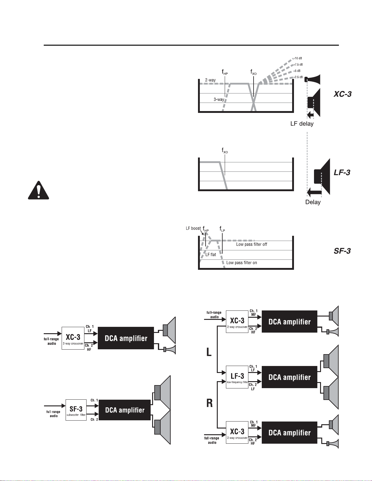
XC-3 This accessory is a two-way crossover, with the low frequency band fed to channel 1 of the amplifier and the high frequencies to
channel 2. An all-pass filter on the low frequency band delays the audio signal, permitting time alignment of a cone driver with
a high-frequency horn. A selectable high-frequency boost circuit provides several increments of compensation for screen loss or
constant-directivity horn equalization. A HF trim control provides 0 to 20 dB of attenuation for matching levels between
frequency bands.
The XC-3 can be used by itself with one amplifier for a 2-way system (shown opposite page, bottom-left), or with the LF-3
and an additional amplifier for 3-way systems, as shown, opposite page, bottom-right. The XC-3 has a pass-through output in
parallel with the input for distributing th e audio signal to the LF-3. The filter circuitry uses a 4th-order Linkwitz-Riley alignment
with 24 dB/octave slopes.
LF-3 Used in a system with the XC-3, the LF-3 performs the low-frequency crossover functions in a 3-way system as shown, opposite
page, bottom-right. Unlike the XC-3, it has two discrete channels; one LF-3 with an amplifier will support two other amplifiers
with two XC-3 accessories, as shown. The 4th-order Linkwitz-Riley low-pass filters have 24 dB/octave slopes.
Each channel has an all-pass filter providing delay for time alignment. Frequency and delay parameters for both channels
are set individually, although typically they would be set the same.
Each channel has a trim control that provides 0 to 20 dB of attenuation for matching levels among the various frequency
bands.
SF-3 The SF-3 Subwoofer Filter has two summed inputs and a bandpass filter that defines the frequency range of the subwoofer
program. The frequencies of the 2nd-order high-pass and 4th-order Linkwitz-Riley low-pass filters are both set by the user
by selecting and installing the appropriate SIP networks. The high-pass filter also has a switchable low-frequency boost
feature: switched on, it provides a 6 dB bump at the selected high-pass frequency, useful for extending the low-end response
of some speaker systems; off, the response is a flat Butterworth curve that is 3 dB down at the selected frequency. The output
is parallel, feeding the same signal into both channels of the amplifier. The SF-3 has no delay function. A level trim control
provides 0 to 20 dB of attenuation.
The SF-3 can be used to derive subwoofer-range program from full-range audio, as shown, opposite page, bottom-left. It can
also be used with a discrete subwoofer channel in cinema sound systems.
Introduction
Description of each model
This manual covers setup and operation of cinema crossover accessories for QSC DCA Digital Cinema Amplifiers. There are three
models: the XC-3 crossover, the LF-3 low frequency filter, and the SF-3 subwoofer filter. Together with DCA amplifiers, they allow
you to assemble any type of cinema sound system, mono or multi-channel.
Each accessory mounts directly to the back of the amplifier by plugging into the amplifier’s DataPort and is secured with three screws.
Operating power and all connections between the accessory and amplifier are provided by the DataPort connection.
Frequency and delay parameters are user-adjustable by inserting selected 8-pin SIP resistor networks into sockets on the underside
of the accessory. A DIP switch permits selection of functions such as delay and high-frequency boost, depending upon model. Each
accessory includes an assortment of the proper SIP resistor networks and three mounting screws. Keep the unused SIPs for future use.
5
CONFIGURING THE ACCESSORIES
Configurable functions of the three accessory models
Configure each accessory before you mount it to the ampli-
fier. If an accessory is already mounted to an amplifier,
always turn the amplifier off before changing switch set-
tings, changing input or output connections, or detaching the
accessory.
Use the tables on the following pages to determine the
correct SIP resistor network value for the desired frequency
and delay settings. SIP identification charts are included to
help you identify the values of the resistor networks. A
flowchart for each model will help you properly configure the
accessory.
NOTE: Even if you don’t use a particular filter or delay
feature on an accessory, put an unused SIP resistor
network of any value into its socket to ensure circuit
stability when it is powered up.
The SIP resistor networks have no polarity and therefore do
not need to be inserted in a certain direction. Make sure all
eight pins are inserted properly into the socket holes, and
then gently but firmly press the network into the socket until
it is fully seated. If a SIP resistor network is difficult to remove
with your fingers, use a small screwdriver, prying gently first
at one end of the SIP and then the other, until it is loose.
Using the XC-3 in a simple two-way system. In many speaker
systems, a passive mid/high combination will handle the higher
frequencies, creating essentially a three-way system.
Using the XC-3 and LF-3 in a stereo three-way system
Using the SF-3 with a discrete subwoofer channel
Configuring the Accessories
 Loading...