


TM
GX POWER AMPLIFIER SERIES
User Manual
GX3 300 watts per channel at 8 ohms GX5 500 watts per channel at 8 ohms GX7 725 watts per channel at 8 ohms
EN
TD-000271-00-F
*TD-000271-00*

2
IMPORTANT SAFETY PRECAUTIONS AND EXPLANATION OF SYMBOLS
1- Read these instructions.
2- Keep these instructions.
3- Heed all warnings.
4- Follow all instructions.
5- WARNING: To prevent fire or electric shock, do not expose this equipment to rain or moisture. Do not use this apparatus near water. 6- Clean only with a dry cloth.
7- Do not block any ventilation openings. Install in accordance with the manufacturer’s instructions.
8- Do not install near any heat sources such as radiators, heat registers, stoves, or other apparatus (including amplifiers) that produce heat. 9- The appliance coupler is the AC mains disconnect and should remain readily operable after installation.
EN 10Do not defeat the safety purpose of the grounding-type plug. A grounding plug has two blades and a grounding prong. The wide blade or third prong are provided for your safety. If the provided plug does not fit your outlet, consult an electrician for the replacement of the obsolete outlet. This apparatus should be connected to a receptacle with a protective earthing (or ground) connection.
11Protect the power cord from being walked on or pinched, particularly at plugs, convenience receptacles, and the point where they exit from the apparatus.
12Use only attachments/accessories specified by QSC Audio Products, LLC
13Use only with hardware, brackets, stands, and components sold with the apparatus or by QSC Audio Products, LLC 14Unplug the apparatus during lightning storms or when unused for long periods of time.
15Refer all servicing to qualified service personnel. Servicing is required when the apparatus has been damaged in any way, such as power supply cord or plug is damaged, liquid has been spilled or objects have fallen into the apparatus, the apparatus has been exposed to rain or moisture, does not operate normally, or has been dropped.
The exclamation point within an equilateral triangle is intended to alert the user to the presence of important operating and maintenance
!(servicing) instructions in this manual.
The lightning flash with arrowhead symbol within an equilateral triangle is intended to alert the user to the presence of uninsulated “dangerous” voltage within the product’s enclosure that may be of sufficient magnitude to constitute a risk of electric shock
to humans.
CAUTION: TO REDUCE THE RISK OF ELECTRIC SHOCK, DO NOT REMOVE THE COVER. NO USER-SERVICEABLE PARTS INSIDE. REFER SERVICING TO QUALIFIED PERSONNEL.
WARNING: To prevent fire or electric shock, do not expose this equipment to rain or moisture.
FCC INTERFERENCE STATEMENT
NOTE: This equipment has been tested and found to comply with the limits for a class B digital device, pursuant to part 15 of the FCC rules. These limits are designed to provide reasonable protection against harmful interference in a residential installation. This equipment generates, uses, and can radiate radio frequency energy and if not installed and used in accordance to the instructions, may cause harmful interference to radio communications. However, there is no guarantee that interference will not occur in a particular installation. If this equipment does cause harmful interference to radio or television reception, which can be determined by switching the equipment off and on, the user is encouraged to try to correct the interference by one or more of the following measures:
Reorient or relocate the receiving antenna.
Increase the separation between the equipment and the receiver.
Connect the equipment into an outlet on a circuit different from that to which the receiver is connected. Consult the dealer or an experienced radio or TV technician for help.
© Copyright 2010, QSC Audio Products, LLC
QSC® is a registered trademark of QSC Audio Products, LLC
“QSC” and the QSC logo are registered with the U.S. Patent and Trademark Office
All trademarks are the property of Speakon® and PowerCon® are registered trademarks of Neutrik LLC their respective owners.

GX POWER AMPLIFIER SERIES3
Professional Power Amplifiers
WELCOME
Thank you for purchasing a QSC Audio amplifier. The GX Series is the latest in a long line of hard-working, low cost amplifiers, designed to produce the best possible results for a wide range of users. In most cases, you can plug and play with no surprises, but for best results, we recommend you review the enclosed user guide.
UNPACKING
Confirm that the amplifier has no visible shipping damage. Confirm that amplifier has the correct AC cord and voltage rating for your region (See rear panel, Serial Number plate). It is best to keep the carton in case the amplifier needs to be returned, at least until it has been tested.
EN |
FEATURES
Power levels matched to the most popular speakers used by entertainers.
SUPPORT AND SERVICE
QSC Audio Products maintains a world-wide network of distributors and service centers. These local agencies will be able to answer your questions and take care of any problems.
QSC WEBSITE
Our website, www.qscaudio.com, is factory-maintained and supported in multiple languages. Visit frequently for new announcements, typical questions, and other user information.
IMPORTANT SAFETY PRECAUTIONS
QSC products are designed for safe operation, and have been certified by recognized product safety agencies to meet all normal standards for this type of product. However, dangerous voltages and power levels exist within the covers of this amplifier. The user is requested to study the precautions in this manual. If the product has been dropped, dented, soaked, or appears to have loose parts inside, the risk of shock is increased. Unplug the AC cord, and take the product to qualified service personnel for inspection and repairs.
POWER RATINGS
Watts at 0.1% clipping, both channels driven
Model |
8 ohms |
4 ohms |
2 ohms* |
GX3 |
300 |
425 |
200 |
GX5 |
500 |
700 |
350 |
GX7 |
725 |
1000 |
600 |
*NOTE: 2-ohm loading is not recommended for high power use. To avoid protective limiting, use only at low levels.
Optimized for maximum real-world headroom into 4Ω and 8Ω speaker systems.
Inputs: XLR, 1/4” TRS and phono input connectors for compatibility with any source.
Outputs: Speakon® combo accepts 1/4” (TS) plugs or Speakon 2-pole and 4-pole plugs (connects 2 poles only). Binding posts support all other speaker wiring systems.
Minimum depth chassis (only 10.1” / 257 mm) fits in compact, inexpensive effects racks.
Light weight – less than 26 lbs (12.5 kg).
Detented gain controls for precise setting and matching of sensitivity.
GuardRail automatically protects the amplifier and loudspeakers from damage due to temperature rise or overdrive without shutting down the show.
Front panel LEDs monitor Power, Signal and Clipping.
Subwoofer / Satellite crossover built-in.

4
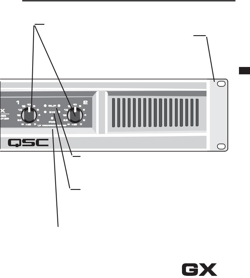
FRONT PANEL FEATURES
ON-OFF SWITCH
Move the rocker switch up to turn on the amplifier. The blue PWR LED will turn on immediately.
The red CLIP LEDs may trigger for 1-2 seconds until the amp has completed its turn-on cycle. If no lights come on, check the power cord and the AC reset on the rear panel.
MODEL NUMBER
The GX3, GX5, and GX7 power ratings are shown on the Specifications page.
|
|
|
COOLING VENTS |
|||
|
|
|
The internal fan moves air through the chassis to |
|||
|
|
|
reduce temperature rise. Keep vents clear. The fan |
|||
EN |
||||||
|
|
speeds up in response to heavy use. |
||||
|
|
|
|
|
|
|
|
|
|
|
|
|
|
|
|
|
|
|
|
|
|
|
|
|
|
|
|
|
|
|
|
|
|
|
|
|
|
|
|
|
|
inches (cm)

5
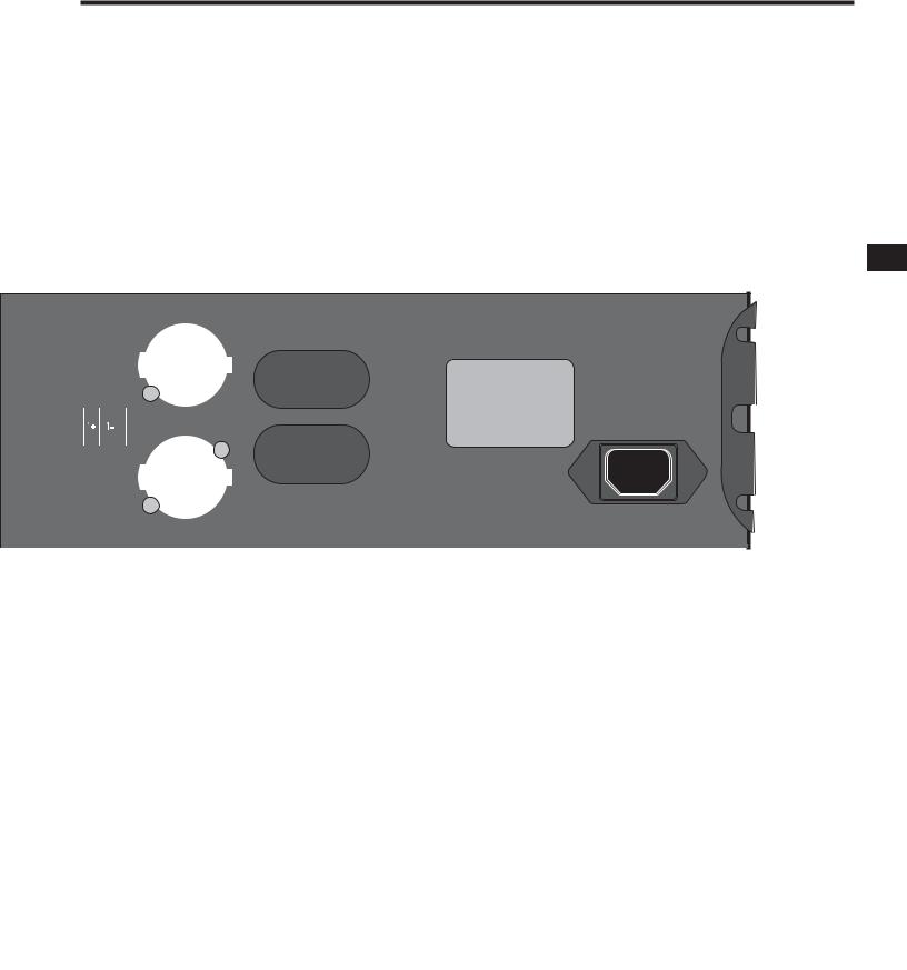
GAIN CONTROLS, CH1, CH2
The markings show attenuation in dB. For normal use, keep the control in the upper half of its range (less than 10 dB of attenuation). If set below half,
the source may overload before the amplifier reaches full power.
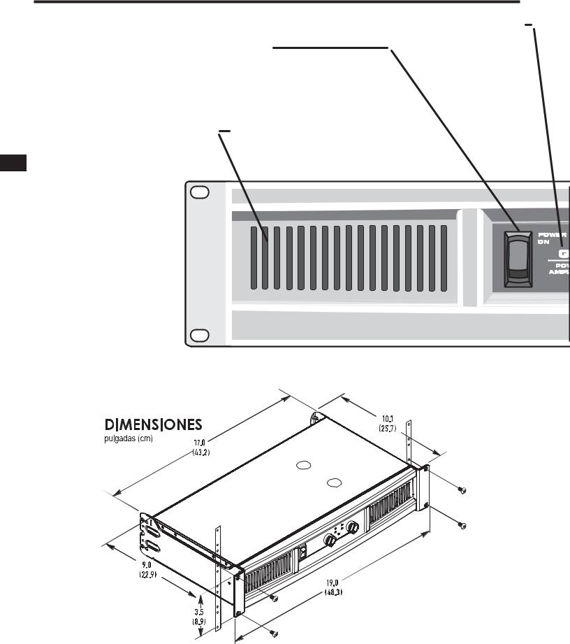
RACK MOUNTING
Fits standard 19-inch rack, 2RU. Accepts #10 or 6 mm screws, as determined by the rack rails. Add rear support to prevent damage in portable rigs.
EN
RED CLIP LEDS
Red flashing indicates the amp is being overdriven. Heavy overdrive triggers internal gain reduction, to reduce overload distortion. Normal gain will resume after the signal level returns to normal. See Troubleshooting if the red LED remains on continuously.
GREEN SIGNAL LEDS
The green LED starts flashing on soft signals (-35 dB), and changes to steady green as the signal level increases.
BLUE POWER LED
The blue PWR (POWER) LED indicates that the AC switch is on, and the amp is receiving power. Within two seconds, it is ready to use.
ALTERNATE GAIN MARKING
When the CROSSOVER switch is active (see rear panel), LF (CH 1) controls low frequencies (subwoofer),
HF (CH 2) controls the high frequencies (mid-high box).
6
REAR PANEL FEATURES
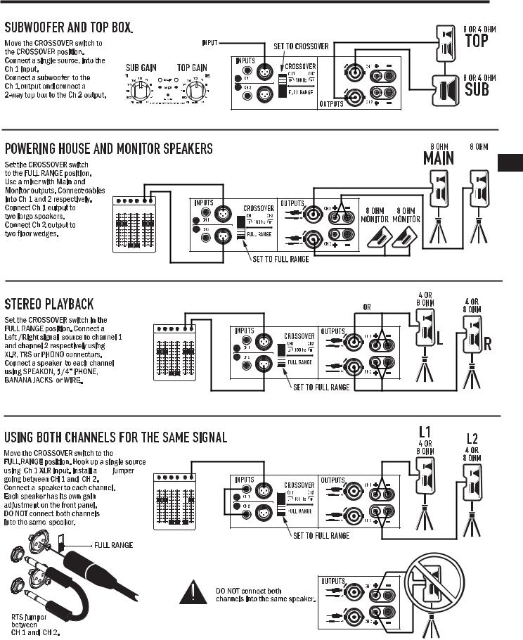
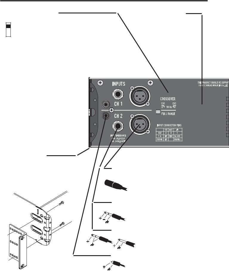
CROSSOVER SWITCH
CROSSOVER POSITION
Splits a full-range signal to drive a subwoofer and top box. CH 1 receives the lows, from 20-100Hz, for the subwoofer. CH 2 receives 100Hz to 20kHz, to power a full range speaker. When using CROSSOVER mode, connect signal to CH 1 only. Use the two Gain controls to balance the LF and HF signals (see Front Panel).
EXHAUST VENT
Keep vent clear. Install in open-back rack.
|
|
|
FULL RANGE POSITION |
|
|
|
|
|
|
|
|
|
|
|
|
|
|
|
|
|
|
|
|
|
|
|
|
||
|
|
|
For normal, 2-channel use with all inputs active. |
|
|
|
|
|
|
|
|
|
|
|
EN |
|
|
|
|
|
|
|
|
|
|
||||
|
|
|
The crossover is bypassed. |
|
|
|
|
|
|
|
|
|
|
|
|
|
|
|
|
|
|
|
|
|
|
||||
|
|
|
|
|
|
|
|
|
|
|
|
|
||
|
|
|
|
|
|
|
|
|
|
|
|
|
|
|
|
|
|
|
|
|
|
|
|
|
|
|
|
|
|
|
|
|
|
|
|
|
|
|
|
|
|
|
|
|
|
|
|
|
|
|
|
|
|
|
|
|
|
|
|
|
|
|
|
|
|
|
|
|
|
|
|
|
|
|
|
|
|
|
|
|
|
|
|
|
|
|
|
|
|
|
|
|
|
|
|
|
|
|
|
|
|
|
|
|
|
|
|
|
|
|
|
|
|
|
|
|
|
|
|
|
|
|
|
|
|
|
|
|
|
|
|
|
|
|
|
|
|
|
|
|
|
|
|
|
|
|
|
|
|
|
|
|
|
|
|
|
|
|
|
|
|
|
|
|
|
|
|
|
|
|
|
|
|
|
|
|
|
|
|
|
|
|
|
|
|
|
|
|
|
|
|
|
|
|
|
|
|
|
|
|
|
|
|
|
|
|
|
|
|
|
|
|
|
|
|
|
|
|
|
|
|
|
|
|
|
|
|
|
|
|
|
|
|
|
|
|
|
|
|
|
|
|
|
|
|
|
|
|
|
|
|
|
|
|
|
|
|
|
|
|
|
|
|
|
|
|
|
|
|
|
|
|
|
|
|
|
|
|
|
|
|
|
|
|
|
|
|
|
|
|
|
|
|
|
|
|
|
|
|
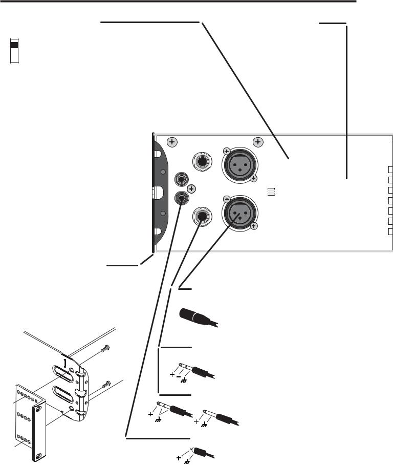
REAR EAR MOUNTING
Rear ears designed for protecting the rear connector wire dressing and supporting the amplifier in a rack. A rear rack support mounting kit (model FG- 000031-00 pack of two) is available from QSC Technical Services Group.
INPUT CONNECTIONS
BALANCED XLR INPUTS
Pin 2 Positive, Pin 3 Negative, Pin 1 Shield (Ground). Recommended for long or short runs, either fixed or frequently changed. Each channel’s XLR and TRS jacks are connected internally, and provide feed thru
to the other connector.
BALANCED 1/4-INCH TRS INPUTS
Tip positive, Ring Negative, Sleeve Shield (Ground). Recommended for long or short runs that are frequently changed.
UNBALANCED 1/4-INCH TS INPUTS
Accepts unbalanced 1/4-inch plugs for short runs.
Tip positive, Sleeve Shield (Ground).
UNBALANCED PHONO INPUTS
Tip Positive, Barrel Shield (Ground). Recommended for semi-permanent connections to nearby sources, within the same rack. NOTE: when using these inputs, the TRS or XLR inputs should not be used.
7
AC BREAKER RESET
If the amplifier shuts off after a long burst of power, turn off the AC switch and check the circuit breaker. The button can be pressed back in after a 30 second cool-down period. If the breaker trips repeatedly,
the amplifier may need servicing.
SERIAL NUMBER AND RATINGS
The rated AC voltage and output power is shown on the serial number plate.
Record the serial number in a safe place.
EN
AC INLET
SPEAKER CONNECTIONS
BINDING POSTS
Accepts banana plugs
(not permitted in CE regions).
Bare wires or terminals may be
inserted into the side holes.
 1/4-INCH CONNECTORS
Insert plug into the center of
the Speakon-Combo jack.
Use only heavy duty speaker cables.
SPEAKON CABLES (2 wire type):
Insert and turn until the connector clicks. Use the thumb latch or locking ring
to release the plug.

8
SYSTEM HOOKUP EXAMPLES
EN |
9
SYSTEM HOOKUP EXAMPLES
 EN
EN
TRS

10
TROUBLESHOOTING
NO POWER, NO LIGHTS, NO FAN
Confirm that the AC cord is fully seated and connected to a live outlet. Check the AC source by trying another device such as a lamp. Check the BREAKER on the back of the amplifier by pushing in the button. If the breaker trips off quickly, the amplifier needs servicing.
AMPLIFIER LOSES VOLUME
If the amplifier is worked too hard, GuardRail™ will
reduce volume to prevent thermal muting. The fan should be running at full speed. Reduce input signal somewhat and the amp should return to normal gain within 1-2 minutes. If the amp feels hot and the fan is not running, it needs to be
EN serviced.
CHANNEL 1 PRODUCES DEEP BASS ONLY.
Check the position of the CROSSOVER switch on the rear panel. Set on FULL RANGE for normal, independent use of each channel.
CHANNEL 2 INPUT SEEMS DEAD.
Check the position of the CROSSOVER switch on the rear panel. Set on FULL RANGE for normal, independent use of each channel.
AMPLIFIER SOUNDS DISTORTED.
If the red CLIP LED is flashing, the amplifier is being played beyond its normal rated power. GuardRail™ circuitry will reduce volume somewhat to prevent severe overdrive, but if the input signal is further increased, the limiter can be overridden, with increased distortion.
If the speakers or speaker cables are shorted or defective, the amplifier may distort at lower-than-normal levels, with increased flashing of the red CLIP LED. This should be checked by trying an alternate speaker and cable.
If too many speakers are connected to each channel (impedance below 4 ohms), the amp will overload more easily and will probably run hot.
If the sound is distorted or garbled without flashing the red CLIP LED, the distortion is not occurring inside the amplifier. Either the speaker is bad or the input signal is distorted.
•Confirm that the speaker is OK by trying a different unit.
•Input overload can occur if the amplifier Gain controls are set too low, and the input source is overdriven to compensate Reduce the source volume until the distortion clears up, and increase amp Gain to reach the desired level. It is generally desireable to keep the amp gains at or near their full, clockwise, position.
•Check all input connections. Do not plug two different sources into the same channel. Use a mixer to blend sources.
NO SOUND, WITH BLUE LED ONLY, NO GREEN OR RED LED
Confirm that the Gain controls are turned up. Confirm that the input cables are correctly installed at both ends. If using 1/4-inch speaker cables, do not confuse with input cables. Confirm that the source is active. If necessary, try another source, or connect another amplifier to the existing source.
NO SOUND, BUT THE GREEN LED IS RESPONDING
The green LED indicates the amp is producing a signal, so sound should be heard if the speaker is connected. Check the speaker connections at both ends, and try a different speaker.
NO SOUND, RED LED ON
The amp mutes briefly when turned on and off to prevent
thumps. If the amp overheats severely, it will mute until it cools off. The fan will be running at full speed, and sound should
resume in less than a minute. If the amp feels hot and the fan is not running, it needs to be serviced.
BACKGROUND HUM
Balanced XLR or TRS cables are better for long runs. Hum can be a problem when connecting to TV-cable rigs, since the TV cable often creates a ground conflict. Request or install a TV-cable isolator to reduce this problem.
Hum can also occur earlier in the signal chain, depending on the types of connections. It often helps to plug everything into the same AC strip, if the total power consumption is not excessive.
As a last resort, mild hum can sometimes be reduced by lowering the amp gain, and increasing the source gain to compensate, but you must ensure that the source can deliver the extra volume without overload distortion. If this does not reduce hum, it is coming from the source.
AMPLIFIER NEEDS SERVICING
The following conditions indicate possible unsafe conditions that require service before using. If observed, unplug the AC cord from the wall and when safe, remove the amp for servicing.
•If the amplifier emits smoke or burning smells
•If the case is severely dented or deformed
•If the amplifier is soaked with any fluid
•If internal parts sound loose
•If the AC breaker trips when power is applied
•If the amplifier is dropped, carefully inspect for damage or loose parts before attempting to use.
11
SPECIFICATIONS
GX3 |
GX5 |
GX7 |
SPECIFICATION SUBJECT TO CHANGE WITHOUT NOTICE.
OUTPUT POWER, 1 kHz, 0.1 % clipping
8Ω, both channels driven |
|
|
300 W |
500 W |
|
725W |
|||
8Ω, single channel driven |
|
|
350 W |
600 W |
|
800W |
|||
4Ω, both channels driven |
|
|
425 W |
700 W |
|
1000W |
|||
4Ω, single channel driven |
|
|
500 W |
850 W |
|
1200W |
|||
2Ω, both channels driven, 1% clipping |
|
200 W |
350 W |
|
600W |
||||
SIGNAL TO NOISE (20 Hz – 20 kHz) |
|
100 dB |
|
|
|
|
|||
INPUT SENSITIVITY |
|
|
1.2 Vrms |
|
|
|
|
||
VOLTAGE GAIN AT 8Ω |
|
|
32.2 dB |
34.4 dB |
|
36.1 dB |
|||
OUTPUT CIRCUITRY |
|
|
Class B |
2-tier Class H |
|
2-tier Class H |
|||
POWER REQUIREMENTS (1/8 power, pink noise |
|
6.3 A |
6 A |
|
10.1 A |
||||
at 4Ω 120 V AC) |
|
|
|
|
|
|
|
|
|
DISTORTION (1 dB below rated power, 1 kHz) |
|
8Ω, less than 0.02% |
|
|
|
|
|||
|
|
|
|
4Ω, less than 0.05% |
|
|
|
|
|
FREQUENCY RESPONSE |
|
|
20 – 20kHz, +0, -1dB |
|
|
|
|
||
DYNAMIC HEADROOM, 4Ω |
|
|
2dB |
|
|
|
|
||
INPUT IMPEDANCE |
|
|
Greater than 20K ohms (balanced or unbalanced) |
|
|
||||
MAXIMUM INPUT LEVEL |
|
|
+24 dB (16 Vrms) |
|
|
|
|
||
INPUT CONNECTORS, each channel |
|
3-pin XLR and 1/4” TRS, balanced, parallel |
|
|
|||||
|
|
|
|
Phono, unbalanced |
|
|
|
|
|
OUTPUT CONNECTORS, each channel |
|
Speakon®, 1/4”, Binding Posts |
|
|
|
|
|||
AMPLIFIER AND LOAD PROTECTION |
|
Short circuit, open circuit, thermal, RF protection |
|
|
|||||
|
|
|
|
Load protected against DC faults |
|
|
|
|
|
CONTROLS AND INDICATORS, FRONT PANEL |
|
Gain controls, 21 detents |
|
|
|
|
|||
|
|
|
|
Red Clip LEDs, proportional, 0.1% THD threshold. |
|
|
|||
|
|
|
|
Green Signal LEDs, threshold -35 dB |
|
|
|||
|
|
|
|
Blue Power LED, AC-on. |
|
|
|
|
|
CONTROLS, REAR PANEL |
|
|
Full Range / Crossover switch |
|
|
|
|
||
|
|
|
|
100 Hz, 3rd order LP (sub), 2nd order HP (top). |
|
|
|||
DIMENSIONS (HWD) |
|
|
3.5” (2RU) x 19” x 10.1” (89 mm x 483 mm x 257 mm) |
|
|
||||
WEIGHT – Shipping / Net |
|
|
31 / 27 lbs (14.1 / 12.1 kg) |
32 / 28 lbs (14.6 / 12.6 kg) |
22 / 17 lbs (10 / 7.7 kg) |
||||
AGENCY APPROVALS |
|
|
UL, CE, RoHS / WEEE compliant. Meets FCC Class B EMI limits. |
|
|||||
|
|
|
|
|
|
|
|||
|
|
AC POWER CONSUMPTION 1/8 power, ohms (AC Current and Heating, 120Vac) |
|
|
|||||
|
|
GX3 |
|
|
GX5 |
|
|
|
GX7 |
Operating Condition |
|
AC amps |
BTU / hr |
|
AC amps |
BTU / hr |
|
AC amps |
BTU / hr |
Idle |
|
0.2 |
44 |
|
0.3 |
60 |
|
0.6 |
82 |
8 + 8 ohms, 1/8 power (1) |
|
4.1 |
904 |
|
3.3 |
734 |
|
7.6 |
1183 |
8 + 8 ohms, 1/3 power (2) |
|
6.1 |
1160 |
|
8.5 |
1456 |
|
13.4 |
1807 |
8 + 8 ohms, full power (3) |
|
9.75 |
1109 |
|
16.2 |
1891 |
|
26.5 |
2167 |
4 + 4 ohms, 1/8 power (1) |
|
6.3 |
1515 |
|
5.8 |
1160 |
|
11.5 |
1908 |
4 + 4 ohms, 1/3 power (2) |
|
9.4 |
2105 |
|
11.2 |
2162 |
|
18.5 |
2612 |
4 + 4 ohms, full power (3) |
|
15.0 |
2297 |
|
24.5 |
3754 |
|
39.4 |
4478 |
EN
(1) 1/8 power represents typical operating conditions.
(3) Full power is breaker limited to short periods.
(2) 1/3 power represents peak program levels.
(4) For 230V, multiply AC current by 0.5. For 100V, multiply AC current by 1.25.

WARRANTY
(USA only; other countries, see your dealer or distributor)
Disclaimer
QSC Audio Products, LLC is not liable for any damage to amplifiers or any other equipment that is caused by negligence or improper installation and/or use of this loudspeaker product.
QSC Audio Products 3 Year Limited Warranty
QSC Audio Products, LLC ( QSC ) guarantees its products to be free from defective material and / or workmanship for a period of three (3) years from date of sale, and will replace defective parts and repair malfunctioning products under this warranty when the defect occurs under normal installation and use - provided the unit is returned to our factory or one of our authorized service
stations via prepaid transportation with a copy of proof of purchase (i.e., sales receipt). This warranty provides that the examination of the return product must indicate, in our judgment, a manufacturing defect. This warranty does not extend to any product which
EN has been subjected to misuse, neglect, accident, improper installation, or where the date code has been removed or defaced. QSC shall not be liable for incidental and/or consequential damages. This warranty gives you specific legal rights. This limited warranty is freely transferable during the term of the warranty period. Customer may have additional rights, which vary from state to state.
In the event that this product was manufactured for export and sale outside of the United States or its territories, then this limited warranty shall not apply. Removal of the serial number on this product, or purchase of this product from an unauthorized dealer, will void this limited warranty. Periodically, this warranty is updated. To obtain the most recent version of QSC’s warranty statement, please visit www.qscaudio.com. Contact us at 800-854-4079 or visit our website at www.qscaudio.com.
How to Contact QSC Audio Products
Mailing address:
QSC Audio Products, LLC 1675 MacArthur Boulevard
Costa Mesa, CA 92626-1468 USA
Telephone Numbers:
Main Number (714) 754-6175
Sales & Marketing (714) 957-7100 or toll free (USA only) (800) 854-4079
Customer Service (714) 957-7150 or toll free (USA only) (800) 772-2834
Facsimile Numbers:
Sales & Marketing FAX (714) 754-6174
Customer Service FAX (714) 754-6173
World Wide Web:
www.qscaudio.com
E-mail: info@qscaudio.com service@qscaudio.com
TM
QSC Audio Products, LLC 1675 MacArthur Boulevard Costa Mesa, California 92626 USA ©2007 “QSC” and the QSC logo are registered with the U.S. Patent and Trademark Office.

TM |
SERIE DE AMPLIFICADORES DE POTENCIA GX |
|
|
|
|
Manual del usuario
GX3 300 vatios por canal a 8 ohmios
GX5 500 vatios por canal a 8 ohmios
GX7 725 vatios por canal a 8 ohmios
SP
TD-000271-00-F
*TD-000271-00*

14
IMPORTANTES PRECAUCIONES DE SEGURIDAD Y EXPLICACIÓN DE LOS SÍMBOLOS
|
1- Lea estas instrucciones. |
|
2- Conserve estas instrucciones. |
|
3- Observe todas las advertencias. |
|
4- Siga todas las instrucciones. |
|
5- ADVERTENCIA: Para prevenir incendios o descargas eléctricas, no exponga este equipo a la lluvia ni a la humedad. |
|
No use este aparato cerca del agua. |
|
6- Límpielo sólo con un paño seco. |
|
7- No obstruya ninguna abertura de ventilación. Instale de acuerdo con las instrucciones del fabricante. |
|
8- No lo instale cerca de fuentes de calor tales como radiadores, registros térmicos, estufas ni otros aparatos (inclusive amplificadores) que |
|
produzcan calor. |
|
9- El acoplador del equipo es la desconexión de la línea principal de CA y debe permanecer fácilmente operable después de la instalación. |
SP |
|
|
10No anule la característica de seguridad del enchufe con conexión a tierra. Un enchufe con conexión a tierra tiene dos hojas y una patilla de |
|
conexión a tierra. La hoja ancha o el tercer terminal se proporcionan para su seguridad. Si el enchufe que se le proporciona no cabe en su tomacorriente, consulte con un electricista para reemplazar el tomacorriente obsoleto. Este aparato debe estar conectado a un receptáculo con una conexión de protección a masa (o tierra).
11Proteja el cable de alimentación para que no se camine sobre él ni se le comprima, particularmente en los enchufes, los receptáculos y el punto en donde éstos salen del aparato.
12Use sólo piezas/accesorios especificados por QSC Audio Products, LLC
13Use sólo con herraje, soportes, estantes y componentes vendidos con el aparato o por QSC Audio Products, LLC
14Desenchufe el aparato durante tormentas eléctricas o cuando no lo vaya a usar durante periodos prolongados de tiempo.
15Refiera todo el servicio a personal calificado. Es necesario dar servicio al aparato cuando sufra algún daño, como cuando se daña el cable de alimentación eléctrica o el enchufe, cuando se derraman líquidos o caen objetos sobre el aparato, cuando éste ha estado expuesto a la lluvia o humedad, cuando no opere normalmente o cuando se haya caído.
!El signo de exclamación dentro de un triángulo equilátero tiene la intención de alertar al usuario de la presencia de importantes instrucciones de operación y mantenimiento (servicio) en este manual.
El símbolo del rayo con una punta de flecha dentro de un triángulo equilátero tiene la intención de alertar al usuario de la presencia de voltaje “peligroso” no aislado dentro de la caja del producto, que puede ser de magnitud suficiente para constituir un riesgo de descarga eléctrica para los seres humanos.
PRECAUCIÓN: PARA REDUCIR EL RIESGO DE DESCARGA ELÉCTRICA, NO QUITE LA CUBIERTA. EL INTERIOR NO CONTIENE PIEZAS A LAS
QUE EL USUARIO PUEDA DAR SERVICIO. REFIERA EL SERVICIO A PERSONAL CALIFICADO.
ADVERTENCIA: Para prevenir incendios o descargas eléctricas, no exponga este equipo a la lluvia ni a la humedad.
DECLARACIÓN DE LA FCC RESPECTO A LA INTERFERENCIA
NOTA: Este equipo ha sido probado y se ha determinado que cumple con los límites de un dispositivo digital Clase B, en virtud de la parte 15 de las reglas de la FCC. Estos límites están diseñados para proporcionar protección razonable contra interferencia dañina en una instalación residencial. Este equipo genera, usa y puede irradiar energía de radiofrecuencia, y si no se instala y usa de acuerdo con las instrucciones, puede causar interferencia dañina a las comunicaciones de radio. Sin embargo, no hay garantía que no ocurrirá interferencia en una instalación en particular. Si este equipo causa interferencia dañina a la recepción de radio o televisión, lo cual se puede determinar al apagar y encender el equipo, se recomienda al usuario que trate de corregir la interferencia en una o más de las siguientes maneras:
Reoriente o reubique la antena receptora.
Aumente la separación entre el equipo y el receptor.
Conecte el equipo en un tomacorriente de un circuito diferente al cual está conectado el receptor. Consulte al distribuidor o a un técnico experimentado de radio o TV para solicitar ayuda.
© Copyright 2010, QSC Audio Products, LLC
QSC® es una marca comercial registrada de QSC Audio Products, LLC
“QSC” y el logotipo de QSC están registrados con la Oficina de Patentes y Marcas Comerciales de los Estados Unidos Speakon® y PowerCon® son marcas registradas de Neutrik LLC y sus respectivos propietarios. Todas las marcas comerciales registradas son propiedad de sus respectivos dueños.

15
SERIE DE AMPLIFICADORES DE POTENCIA GX
Amplificadores profesionales de potencia
BIENVENIDO
Gracias por adquirir un amplificador de QSC Audio. La serie GX es la última de una larga línea de amplificadores resistentes y de bajo costo, diseñados para producir los mejores resultados a una gran variedad de usuarios. En la mayoría de los casos, puede enchufar y reproducir sin sorpresas, pero para obtener resultados óptimos, recomendamos que revise la guía del usuario adjunta.
DESEMBALAJE
Confirme que el amplificador no haya sufrido daños visibles durante el envío. Confirme que el amplificador tenga el cable de CA y la clasificación de voltaje correctos para su región (consulte la placa con el número de serie en el panel posterior). Es buena idea guardar la caja en el caso de que sea necesario devolver el amplificador, al menos hasta el momento de haberlo probado.
ASISTENCIA Y SERVICIO TÉCNICO
QSC Audio Products mantiene una red internacional de distribuidores y centros de servicio. Estas agencias locales podrán responder sus preguntas y solucionar cualquier problema.
|
SITIO WEB DE QSC |
|
Nuestro sitio web, www.qscaudio.com, se mantiene en la fábrica y |
|
está disponible en varios idiomas. Visítelo frecuentemente para leer |
|
los anuncios nuevos, ver las preguntas típicas y enterarse de otra |
do |
información para el usuario. |
PRECAUCIONES IMPORTANTES DE SEGURIDAD
Los productos de QSC están diseñados para su operación segura, y agencias reconocidas de seguridad de los productos certifican que cumplen con todas normas habituales para este tipo de producto. Sin embargo, dentro de este amplificador existen voltajes peligrosos y niveles de potencia. Se solicita al usuario leer las precauciones en este manual. Si el producto se ha caído, abollado, mojado o parece tener piezas sueltas en su interior, se aumentará el riesgo de sufrir descargas eléctricas. Desenchufe el cable de CA y lleve el producto al personal de servicio calificado para su inspección y reparaciones.
CLASIFICACIONES DE POTENCIA
Vatios a un recorte del 0.1%, ambos canales excitados
Modelo |
8 ohmios |
4 ohmios |
2 ohmios* |
|
|
|
|
GX3 |
300 |
425 |
200 |
GX5 |
500 |
700 |
350 |
|
|
|
|
GX7 |
725 |
1000 |
600 |
SP
CARACTERÍSTICAS
Niveles de potencia equiparados a los altavoces más populares usados por los artistas.
Optimizado para un máximo espacio libre del mundo real en sistemas de altavoces de 4Ω y 8Ω.
Entradas: Conectores XLR, TRS de 1/4” y de entrada de sonido compatibles con cualquier fuente.
Salidas: La combinación Speakon® acepta enchufes de 1/4” (TS) o enchufes Speakon de 2 polos y de 4 polos (sólo conecta 2 polos). Los bornes de conexión aceptan todos los demás sistemas de cableado de altavoces.
El chasis de profundidad mínima (sólo 10.1” / 257 mm) cabe en bastidores para equipo de efectos, que son compactos y económicos.
Liviano – menos de 26 lbs (12.5 kg).
Controles de ganancia con retenes para ajustar y equiparar la sensibilidad.
GuardRail automáticamente protege el amplificador y los altavoces contra daños debido al aumento de la temperatura o a la sobreexcitación sin interrumpir el espectáculo.
Los indicadores LED del panel frontal supervisan la potencia, la señal y el recorte.
Cruce de subwoofer / satelital incorporado.
*NOTA: No se recomienda una carga de 2 ohmios para uso a alta potencia. Para evitar la limitación de protección, utilícelo sólo a niveles bajos.
16
CARACTERÍSTICAS DEL PANEL FRONTAL
CONMUTADOR DE ENCENDIDO-APAGADO
Mueva el conmutador basculante hacia arriba para encender el amplificador. El indicador LED azul PWR se encenderá inmediatamente.
Los indicadores LED rojos CLIP pueden activarse durante 1-2 segundos hasta que el amplificador haya completado su ciclo de encendido. Si no vuelven a encenderse las luces, verifique el cable de alimentación y el restablecimiento de CAen el panel posterior.
NÚMERO DE MODELO
Las clasificaciones de potencia GX3 y GX5 se muestran en la página de especificaciones.
ABERTURAS DE VENTILACIÓN
El ventilador interno mueve el aire a través del chasis para reducir el aumento de temperatura. Mantenga las aberturas
SP libres de obstrucciones. El ventilador se acelera como respuesta al uso pesado.
17
CONTROLES DE LA GANANCIA, CH1, CH2
Las marcas muestran la atenuación en dB. Para uso normal, mantenga el control en la mitad superior de su intervalo (menos de 10 dB de atenuación). Si se ajusta por debajo de la mitad, la fuente de la señal puede sobrecargarse antes de que el amplificador
llegue a la máxima potencia.
MONTAJE EN BASTIDOR
Cabe en un bastidor estándar de 19 pulgadas, 2RU.
Acepta tornillos número 10 o de 6 mm, dependiendo de los rieles del bastidor. Añada un soporte posterior para evitar
daños en el equipo portátil.
SP
INDICADORES LED ROJOS DE RECORTE
Si parpadean de color rojo, significa que el amplificador está siendo sobreexcitado. Una sobreexcitación significativa activa una reducción interna de la ganancia, para reducir la distorsión de la sobrecarga. Cuando el nivel de la señal regrese a su nivel normal, se reanudará la ganancia normal . Consulte la sección sobre resolución de problemas si el indicador LED rojo permanece encendido de manera continua.
INDICADORES LED VERDES DE SEÑAL
El indicador LED verde comienza a parpadear al haber señales tenues (-35 dB), y cambia hasta ponerse verde permanente a medida que aumenta el nivel de la señal.
INDICADOR LED DE ENCENDIDO
El indicador LED azul PWR (encendido) indica que el conmutador de CA está encendido, y que el amplificador está recibiendo alimentación. Al cabo de dos segundos, está listo para usar.
MARCA DE GANANCIA ALTERNATIVA
Cuando el conmutador CROSSOVER (cruce) está activo (consulte el panel posterior), LF (CH 1) controla las bajas frecuencias (subwoofer),
HF (CH 2) controla las altas frecuencias (caja media-alta).
18
CARACTERÍSTICAS DEL PANEL POSTERIOR
CONMUTADOR DE CRUCE
POSICIÓN DE CRUCE
Divide una señal de intervalo completo para excitar un subwoofer y caja superior. El canal CH 1 recibe los bajos, de 20 a 100Hz, para el subwoofer.
El canal CH 2 recibe 100Hz a 20kHz, para alimentar un altavoz de intervalo completo.
Al usar el modo CROSSOVER, conecte la señal únicamente a CH 1. Utilice los dos controles de ganancia para equilibrar las señales LF y HF (consulte el panel frontal).
ABERTURA DE DESCARGA
Mantenga la abertura libre de obstrucciones. Instale en un bastidor de fondo abierto.
|
|
|
POSICIÓN DE INTERVALO COMPLETO |
|
|
|
|
|
|
||||
|
|
|
|
|
|
|
|
|
|||||
|
|
|
Para un uso normal con 2 canales, utilice con todas las entradas |
|
|
|
|
|
|
||||
SP |
|
|
|
|
|
|
|||||||
|
|
|
activas. El cruce se elude. |
|
|
|
|
|
|
||||
|
|
|
|
|
|
|
|||||||
|
|
|
|
|
|
|
|
|
|||||
|
|
|
|
|
|
|
|
|
|
|
|
|
|
|
|
|
|
|
|
|
|
|
|
|
|
|
|
|
|
|
|
|
|
|
|
|
|
|
|
|
|
|
|
|
|
|
|
|
|
|
|
|
|
|
|
|
|
|
|
|
|
|
|
|
|
|
|
|
|
|
|
|
|
|
|
|
|
|
|
|
|
|
|
|
|
|
|
|
|
|
|
|
|
|
|
|
|
|
|
|
|
|
|
|
|
|
|
|
|
|
|
|
|
|
|
|
|
|
|
|
|
|
|
|
|
|
|
|
|
|
|
|
|
|
|
|
|
|
|
|
|
|
|
|
|
|
|
|
|
|
|
|
|
|
|
|
|
|
|
|
|
|
|
|
|
|
|
|
|
|
|
|
|
|
|
|
|
|
|
|
|
|
|
|
|
|
|
|
|
|
|
|
|
|
|
|
|
|
|
|
|
|
|
|
|
|
|
|
|
|
|
|
|
|
|
|
|
|
|
|
|
|
|
|
|
|
|
|
|
|
|
|
|
|
|
|
|
MONTAJE EN LAS OREJAS POSTERIORES
Hay orejas posteriores diseñadas para proteger el aislamiento de los hilos del conector posterior y soportar el amplificador en un bastidor. Está disponible un juego de montaje de apoyo en el
bastidor posterior (modelo FG-000031-00, paquete de dos unidades) en el Grupo de Servicios Técnicos de QSC.
CONEXIONES DE ENTRADA
ENTRADAS XLR EQUILIBRADAS
Patilla 2 Positivo, Patilla 3 Negativo, Patilla 1 Blindaje (Tierra). Recomendadas para tramos largos o cortos, fijos o que se cambian frecuentemente. Los enchufes XLR y TRS de cada canal se conectan internamente, y proporcionan un pasaje al otro conector.
ENTRADAS EQUILIBRADA Y TRS DE 1/4 DE PULGADA
Punta Positivo, Anillo Negativo, Funda Blindaje (Tierra). Recomendadas para tramos largos o cortos que se cambian con frecuencia.
ENTRADAS DESEQUILIBRADA Y TS DE 1/4 DE PULGADA
Acepta enchufes desequilibrados de 1/4 de pulgada para tramos cortos. Punta Positivo, Funda Blindaje
 (Tierra).
ENTRADAS DESEQUILIBRADAS DE SONIDO
Punta Positivo, Cilindro Blindaje (Tierra). Recomendadas para conexiones semipermanentes a fuentes cercanas, dentro del mismo bastidor. NOTA: al usar estas entradas, no deben usarse las entradas TRS o XLR.
 Loading...