


Service Bulletin
Title: |
DCM-1 Power Cycle Update |
|
|
Bulletin #: |
DCM0001 |
Issue Date: |
January 30, 2001 |
Models Affected: |
DCM-1 |
Bulletin Revision: |
A |
Production Range: |
January 1999–August 2000 (serial # range: see “Units Affected,” below) |
||
Description
When the DCM-1 is turned off and then turned on again within 15 seconds, the front panel LEDs do not respond to the monitor selector buttons. Any amplifiers connected to the DCM remain in standby. If the DCM-1 is turned off and after 15 seconds, turned on again, the unit will operate as normal.
Units Affected
Only DCM-1 units manufactured from January 1999 through August 2000 are affected. The first four digits of the serial number indicate the year and week of manufacture in YYWW form (e.g., “0021” is the 21st week of the year 2000). Thus, the units affected by this bulletin have serial numbers between 9901xxx and 0024xxx.
Instructions
Tools and materials required:
•Grounded anti-static wrist band and work surface
•Personal computer with Windows (95/98/2000/NT/ME) operating system and Lattice Semiconductor ispVM™ System software (downloadable from Lattice Semiconductor’s web site: http://www.latticesemi.com) and QSC DCM Commander software installed
•ispDOWNLOAD™ cable and parallel port interface box (available from Lattice Semiconductor)
•RS-232 serial cable (straight through)
•DataPort cable
•JEDEC file containing the update code (available from QSC Technical Services)
•0.031" (0.8 mm) diameter rosin-core solder (60/40 or 63/37 eutectic type)
•Soldering iron with fine tip
•Desoldering equipment or solder braid
•8-pin, 0.1”-center right-angle male header (QSC part # CO-000083-00, a 10-pin right-angle header; prepare by cutting off 2 pins at one end)
•DCM input test cable (see last page)
•DCA amplifier
•8-ohm resistive load with power rating adequate for the DCA amplifier
•Sinusoidal audio signal generator
•Oscilloscope
CAUTION: Take appropriate anti-static precautions to guard against electrostatic discharge (ESD).
Figure 1. Locate and remove solder from the eight pads at P11 (inside the rectangle). The component side of the rear panel PCB is shown.
Procedure: Installing the download header
1.Connect the DCM-1 to the computer’s RS-232 port via the serial cable. Turn on the DCM-1 and verify that it operates properly. If the front panel stops responding, turn off the unit, wait 15 seconds, and turn it back on. Once the DCM-1 is functioning correctly, open the DCM Commander application on the computer.
DCM0001 |
1 |
2.Select Connect to DCM from the Communication menu. Then select Read Configuration from DCM, also from the
Communication menu. This will load the configuration parameters currently programmed into the DCM-1 into the DCM Commander application.
3.Select Save as … from the File menu. Choose a filename and location, and save the configuration. This configuration will be restored to the DCM-1 later, after the modification and testing are done.
4.Turn off the DCM-1 and remove the 11 screws securing the top cover of the DCM-1, and then lift off the cover.
5. Locate P11 on the back side of the rear panel printed circuit board (PCB) and remove the solder from the eight pads (Figure
1). P11 is easier to find if you remove the PCB, but if you already are familiar with its location you can save time by leaving the PCB attached to the chassis.
6.The right-angle header can be installed either way, with the pins pointing left or right. Solder the header in place at P11. The square pad is pin 1 (toward the top of the PCB). Locate pin 5 and cut it off.
7.Connect the header at P11 to the PC’s parallel port via the ispDOWNLOAD cable and parallel port interface box.
Procedure: Downloading the JEDEC code
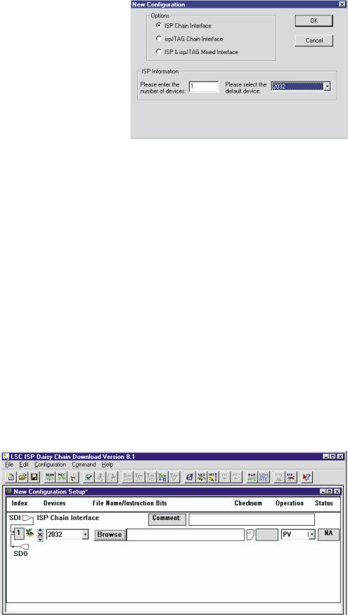
1.Open the ispVM System application. Click the ispDCD button to open the daisy chain download program. Select New from the File menu.
In the New Configuration dialog box, select the ISP Chain Interface option. Under ISP Information, enter 1 as the number of devices, and select the 2032 chip as your default device (Figure 2).
2.In the New Configuration Setup window, click the Browse button. Search for the correct JEDEC file and see that the file path appears in the text box to the right of the Browse button (Figure 3).
3.In the Operation list, select PV.
4.Now turn the DCM-1 on and wait about 3 seconds for it to complete its turn-on sequence.
5.In the ispVM System application, press CTRL+R or click the run button. After downloading the new code, the application will display some text in the Messages window and also a word in the Status box that indicates whether the operation was successful: “Pass” means the new code has been downloaded without error, while “Fail” means some problem occurred. If the download was unsuccessful, make
sure the DCM-1 has AC power and the ispDOWNLOAD cable is oriented and connected correctly, and then start the procedure over again.
6.Turn off the DCM-1 and disconnect the ispDOWNLOAD cable.
Figure 3. Browse for the JEDEC update file. When you select the file, the path will appear in the text box to the right of the Browse button.
2 |
DCM0001 |
 Loading...