


 Loading...
1675 MacArthur Blvd., Costa Mesa, CA, 92626 USA
Main Number (714) 754-6175 or toll free (USA only) (800) 854-4079 Customer Service(714) 957-7150 or toll free (USA only) (800) 772-2834
MD Series Powered Loudspeaker Products
User Manual Manual del Usuario Manuel d'utilisation Benutzerhandbuch
MD-LP115
MD-LP118
MD-SP215
MD-SP218
1 x 15-inch Low-frequency
1 x 18-inch Low-Frequency
2 x 15-inch Subwoofer
2 x 18-inch Subwoofer
EN
ES
FR
DE
CH
*TD-000196-00*
TD-000196-00 rev.B
Important Safety Precautions & Explanation of Symbols
Install in accordance with QSC Audio Product's instructions and under the supervision of a licensed Professional Engineer.
 WARNING!
CAUTION: TO REDUCE THE RISK OF ELECTRIC SHOCK, DO NOT REMOVE THE COVER. NO USER-SERVICEABLE PARTS INSIDE. REFER SERVICING TO QUALIFIED PERSONNEL.
EN
The lightning flash with arrowhead symbol within an equilateral triangle is intended to alert the user to the presence of uninsulated “dangerous” voltage within the product's enclosure that may be of sufficient magnitude to constitute a risk of electric shock to humans.
The exclamation point within an equilateral triangle is intended to alert the user to the presence of important operating and maintenance (servicing) instructions in this manual.
1- Read these instructions.
2- Keep these instructions.
3- Heed all warnings.
4- Follow all instructions.
5- WARNING: To prevent fire or electric shock, do not expose this equipment to rain or moisture. Do not use this apparatus near water.
6- Clean only with a dry cloth.
7- Allow a minimum of 4” (100mm) clearance at cabinet back for convection cooling. Keep anything that might restrict airflow away from the rear of the enclosure (i.e draperies, fabric, etc...). Do not block any ventilation openings. This product contains an internal power amplifier that produces heat.
8- Do not install near any heat sources such as radiators, heat registers, stoves, or other apparatus (including amplifiers) that produce heat.
9- Do not defeat the safety purpose of the polarized or grounding-type plug. A polarized plug has two blades with one wider than the other. A grounding plug has two blades and a grounding prong. The wide blade or third prong are provided for your safety. If the provided plug does not fit your outlet, consult an electrician for the replacement of the obsolete outlet.
10Protect the power cord from being walked on or pinched, particularly plugs, convenience receptacles, and the point where they exit from the apparatus.
11Use only attachments/accessories specified by QSC Audio Products, Inc.
12Use only with hardware, brackets, stands, and components sold with the apparatus or by QSC Audio Products, Inc. 13Unplug the apparatus during lightning storms or when unused for long periods of time.
14Refer all servicing to qualified service personnel. Servicing is required when the apparatus has been damaged in any way, such as power supply cord or plug is damaged, liquid has been spilled or objects have fallen into the apparatus, the apparatus has been exposed to rain or moisture, does not operate normally, or has been dropped.
15Before placing, installing, rigging, or suspending any speaker product, inspect all hardware, suspension, cabinets, transducers, brackets and associated equipment for damage. Any missing, corroded, deformed, or non-load rated component could significantly reduce the strength of the installation, placement or array. Any such condition severely reduces the safety of the installation and should be immediately corrected. Use only hardware which is rated for the loading conditions of the installation and any possible short-term, unexpected overloading. Never exceed the rating of the hardware or equipment.
16Consult a licensed, Professional Engineer regarding physical equipment installation. Ensure that all local, state and national regulations regarding the safety and operation of flying equipment are understood and adhered to.
FCC Interference Statement
NOTE: This equipment has been tested and found to comply with the limits for a class B digital device, pursuant to part 15 of the FCC rules. These limits are designed to provide reasonable protection against harmful interference in a residential installation. This equipment generates, uses, and can radiate radio frequency energy and if not installed and used in accordance to the instructions, may cause harmful interference to radio communications. However, there is no guarantee that interference will not occur in a particular installation. If this equipment does cause harmful interference to radio or television reception, which can be determined by switching the equipment off and on, the user is encouraged to try to correct the interference by one or more of the following measures:
•Reorient or relocate the receiving antenna.
•Increase the separation between the equipment and the receiver.
•Connect the equipment into an outlet on a circuit different from that to which the receiver is connected.
•Consult the dealer or an experienced radio or TV technician for help.
2

Introduction
Congratulations and thank you for your purchase of this professional, powered loudspeaker product. To get the most from your investment, we recommend you review all the information provided in this User Manual.
The Modular Design (or “MD”) self-powered loudspeakers provide excellent sound, power amplification on-board, and a multitude of models with common cabinet design making installation easier. Multiple pick points and minimal weight increase over non-powered versions enable the powered MD series to solve more application challenges than competing designs. Available in black or white, they are the perfect solution for house-of- worship, performing arts center, and arena applications that demand flexible and excellent-sounding system solutions. Handles are provided on black-colored enclosures, while white-colored enclosures omit handles for a cleaner appearance.
All models are self-powered, using highly efficient class-D amplifiers and switch-mode power supplies. AC line connection is fast and easy; a locking, quick-disconnect Neutrik PowerCon® ensures reliable AC mains connection while providing an easy-to-remove power cord for cabinet mobility. Audio is input to the self-powered loudspeaker via an XLR connector with an additional XLR output for daisy-chaining. Features vary by model, so please refer to the specifications for specific model information.
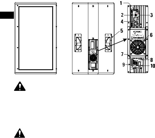
MD-LP shown (MD-SP similar)
EN
1- Filter Switch
2- Gain Adjuster
3- Green Signal and Red Clip Indicator LEDs
4- Input and Output XLR connectors
5- Handles, only on black enclosures
6- Cooling Fan
7- AC Mains Entrance
8- Blue Power ON LED Indicator
9- Serial Number Plate
10Power Switch (AC Mains Switch)
NOTE! Handles are provided on black-colored enclosures only! White-colored enclosures are not equipped with handles.
Installation
There are fifteen (15) load-rated pick points on the MD-LP enclosure and sixteen (16) on the MD-SP enclosure. As shipped from the factory, each pick point has a strength rated flat head bolt installed. These bolts are load bearing components of the enclosure. Do not remove these bolts except to replace a bolt with a forged-shoulder eye bolt. If a flat head screw is lost, contact QSC’s Technical Services department for a replacement.
Ensure all pick-point fasteners are installed and tightened to 40 in-lb (4.519 N-m) to maintain enclosure’s rated strength. Air leaks resulting from missing hardware will degrade the loudspeaker’s performance.
For eye bolt suspension, use only 3/8-inch, 16 threads per inch forged shoulder eye bolts, QSC part number SR-000096-00. Contact QSC Technical Services department for complete information.
Before placing, installing, rigging, or suspending any speaker product, inspect all hardware, suspension, cabinets, transducers, brackets and associated equipment for damage. Any missing, corroded, deformed, or non-load rated component could significantly reduce the strength of the installation, placement or array. Any such condition severely reduces the safety of the installation and should be immediately corrected. Use only hardware which is rated for the loading conditions of the installation and any possible short-term, unexpected overloading. Never exceed the rating of the hardware or equipment.
Consult a licensed, Professional Engineer regarding physical equipment installation. Adhere to all regulations regarding the safety and operation of flying equipment.
3

Installation (continued)
Cooling
EN
This product’s internal power amplifier produces some heat as a normal condition of operation. Allow a minimum of 4” (100mm) clearance at cabinet back for adequate ventilation, and avoid exposing to hot lights or direct sunlight. For ambient temperatures below 104°F (40°C) the fan will normally remain off. Between 104°F (40°C) and 122° (50°F) the fan will run for increasing periods of time. Above 130°F (55°C) the internal overheating protection will begin to operate. The unit will reduce its gain, and possibly mute. If the fan appears to be running constantly, try to reduce the ambient temperature to ensure full performance.
Keep anything that might restrict airflow away from the rear of the enclosure (i.e draperies, fabric, etc...).
Do not install enclosures with their rear panels exposed to direct sunlight. Direct sunlight will heat the amplifier module and reduce its ability to produce full output. Install sunshades if the application merits.
Maximum ambient temperature for full performance to specification is 45° C. (113° F.).
Do not install enclosures where exposed to rain or other water sources. The enclosure is not weatherproof. Outdoor installations must provide protection from the elements.
AC Mains
AC Mains Connection
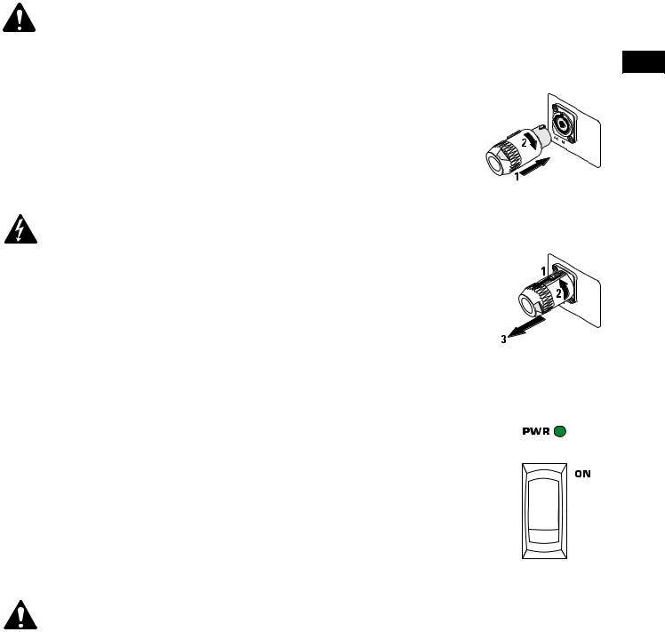
Orient the PowerCon connector with the PowerCon socket located on the rear panel of the loudspeaker. It is keyed and will only fit into the socket when aligned properly. Insert the connector fully and rotate clockwise until the locking mechanism engages.
The correct AC line voltage is shown on the serial number label, on the rear panel. Connecting to the wrong line voltage may damage the amplifier or increase the risk of electric shock.
AC Mains Disconnection
To remove the connector, pull back on the metal locking tab and turn the connector counterclockwise until it stops, then pull to remove the connector form the socket.
Power Switch
Push in on the top of the rocker switch to apply AC mains power to the powered loudspeaker. Push in on the bottom of the rocker switch to turn the powered loudspeaker off.
When turned on, the blue Power indicator LED and the red LIM (limiter) indicator LED will illuminate; after a few seconds the red LIM indicator will extinguish.
LED Power Indicator
The blue LED Power indicator will illuminate when the AC Power switch is in the “ON” position, the AC mains power cord is connected properly, and the AC mains are functioning properly. The LED Power indicator will extinguish when the AC Power switch is in the “off” position or AC mains power has been removed from the loudspeaker.
If the Power indicator does not illuminate when the Power switch is placed in the “on” position, verify the AC mains line cord is properly attached to the loudspeaker and plugged into the AC outlet. Verify the outlet is functioning properly.
If the AC mains cordset is serviceable and the AC mains outlet is operating properly, but the loudspeaker fails to operate, the loudspeaker may require servicing. Contact QSC’s Technical Services department.
4
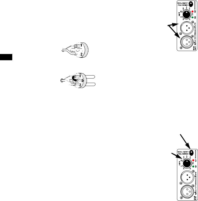
Input/Output Connections
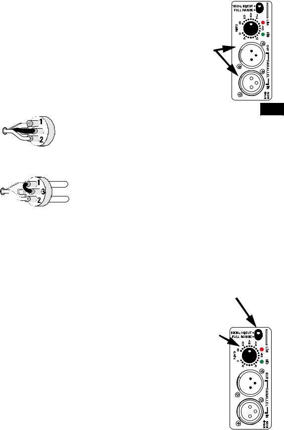
The MD has a balanced 3-pin female XLR input marked IN and a male XLR output connector marked OUT. The IN and OUT connectors are wired in parallel, enabling connection of multiple enclosures in a “daisy-chain” fashion.
Balanced connections are recommended for less AC hum and interference, especially with long cable runs. Unbalanced connections may be suitable for short cables. The signal's source impedance should be less than 600 ohms.
Input connection
Insert the male XLR input into the jack marked IN. Ensure the connector is fully seated. The input impedance is 12k ohm balanced or 6k ohm unbalanced.
Balanced inputs: Connect to the plug as shown.
 1= shield (ground)


 3= minus (-)
 2= plus (+)
Unbalanced inputs: Connect to the plug as shown. Pin 3 and pin 1 must be connected with a jumper as shown.
1= shield (ground)
 3= jumper to pin 1 2= plus (+)
Output Connection
Insert the female XLR connector into the jack marked OUT. Connect the other end of the cable to the next down-stream audio device’s input connector.
Gain Control
The Gain control is recessed and can be adjusted with a small screwdriver or flat tool. Turn the gain control clockwise to increase gain and counter clockwise to decrease gain. The attenuation in dB (from maximum) is shown on the label.
The Gain control is marked in dB of attenuation. There are 21 detents for repeatable adjustments. The upper 14 steps are about 1 dB each, and settings should normally be made within this range. The range below -14 dB should not be used for normal program levels, as the input headroom could be exceeded, but can be used for testing at reduced levels. At the minimum setting, the signal is completely cut off.
Filter Select Switch
Above the Gain control is a small toggle switch that selects either Full Range input or applies a 100 Hz Hi-Cut filter to the input signal.
100 Hz Hi-Cut Setting (Lo-Pass Setting)
Engages an internal fourth-order crossover filter. It is designed to work with the 100 Hertz Lo-Cut filter on twoway, powered MD loudspeakers, forming an acoustically matched crossover without external processing.
Full Range Setting
Use the Full Range setting for applications with upstream filtering or signal processing. This allows tailoring of the sound to your tastes using your signal processing. The input signal must be appropriately processed for the enclosure (i.e. low frequency signal only). Do not apply a full-range audio input as the internal high-frequency protection circuit may shut down the amplifier.
Do not apply an input signal with high-frequency content when Full Range is selected!
Input (IN) and
Output (OUT)
Connectors
EN
Filter Select Switch
Gain Control
5
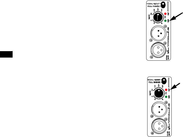
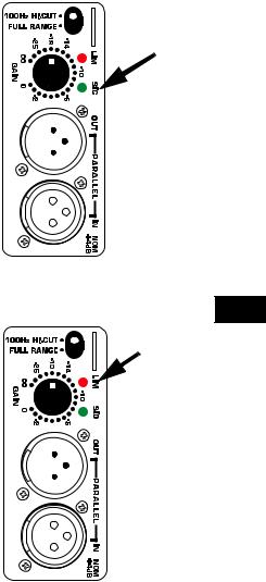
SIG (Signal) Indicator LED
The green SIG (signal) indicator alerts the user to the presence of an input signal to the MD loudspeaker.
Normal Indication
The green SIG indicator illuminates when the input signal exceeds -25 dB.
If No Indication
Check Gain settings and increase gain if necessary. Check input connections and audio source for signal. If the red LIM LED illuminates, refer to the LIM indicator section, below.
Abnormal Indication
If the green SIG LED illuminates with no signal input, there may be system oscillations or some EN other malfunction. Disconnect the input or fully reduce the gain. If the green SIG LED remains
on, the amp may need servicing.
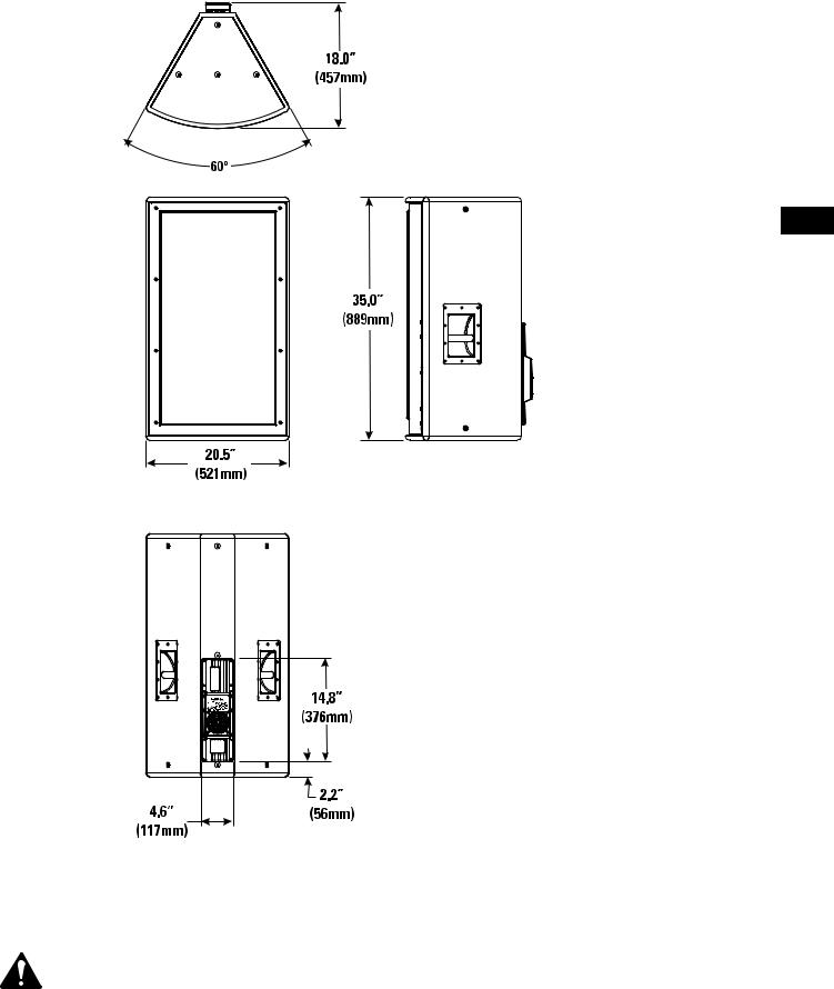
LIM (Limiter) Indicator LED
The red LIM indicator alerts the user to several abnormal conditions within the MD loudspeaker:
Continuous Bright Red Light
•Indicates protective mute mode.
•The speaker normally mutes for several seconds after applying power, after which the light should go out, and sound should be heard.
•If the speaker enters Mute during operation, it has either overheated or developed a fault.
•Overheating should correct itself within 1-2 minutes, after which sound should resume. See below for a full explanation of thermal protection.
•Short periods of muting could indicate excessive high-frequency program with subwoofer set at Full-Range. If this is not the case, it could indicate a component fault; remove AC power and have the speaker serviced.
Momentary Bright Red Flashes
•During operation, bright flashing indicates clipping (overdrive distortion).
•This is normally due to excessive volume, and will likely be accompanied by audible distortion.
•If the speaker mutes repeatedly during peaks, there may be a component fault. AC power should be removed and the speaker serviced.
Continuous Half-Bright Light
•Indicates that the internal limiter is reducing gain, due to prolonged clipping and/or excessive temperature.
•After several seconds of severe clipping, the limiter will reduce power to protect the speaker and improve the sound. This results in a steady, half-bright red indication. Any further clipping will still result in bright flashes on top of the steady half-bright indication. When the program level is reduced, the limiter will clear after several seconds, and the red indicator will go out.
•If the power module overheats despite fan operation, the first response is to trigger limiting, to reduce volume and limit further temperature rise. This results in a steady half-bright illumination that does not clear even after reducing program level. It may take several minutes for temperature to drop and clear the limiter. During this time, the exposed heat sink will feel uncomfortably hot to the touch and the fan should be running. If overheating continues, the amplifier will ultimately mute, resulting in a full-bright red indication. When muting clears, the amplifier will resume operation, with thermal limiting still active until it further cools off.
•Overheating is usually caused by excessive ambient temperature, since the internal temperature rise of the Class-D power module is relatively low. Protect the speaker from excessive temperatures, such as being placed over a heater vent, or allowing direct sunlight to impinge upon the heat sink surface.
SIG (signal) indicator LED
LIM (limiter) indicator LED
6
Dimensions MD-LP115 and MD-LP118
EN
NOTE! Handles are provided on black-colored enclosures only! White-colored enclosures are not equipped with handles.
7

Dimensions MD-SP215
EN
Dimensions MD-SP218
8
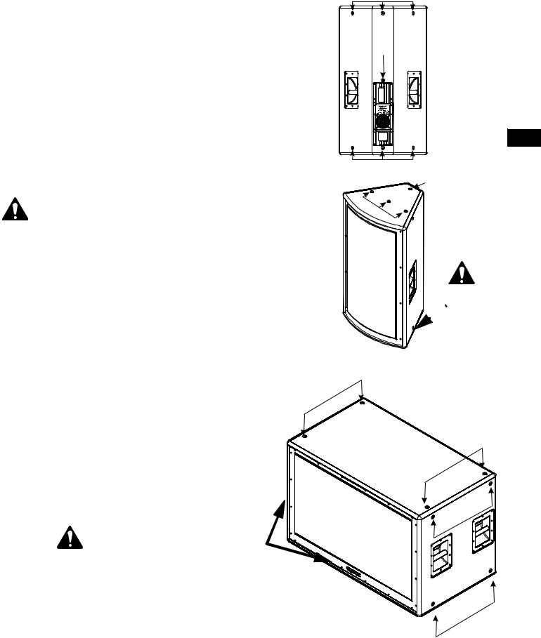
Location of Pick Points
There are fifteen (15) load-rated pick points on MD-LP enclosures; four each on the top and on the bottom, two each on the sides, and three on the rear of the enclosure.
There are sixteen (16) load-rated pick points on MD-SP enclosures; four each on the top and on the bottom, and four each on the sides.
These pick points are indicated with arrowheads on the illustrations. Note the pick points on the cabinet bottom or sides are not shown, but are identical to those indicated on the cabinet top (MD-LP) or the side shown (MD-SP).
As shipped from the factory, each pick point has a strength-rated flat head bolt installed. These bolts are load bearing components of the enclosure. Do not remove these bolts except to replace a bolt with a forged-shoulder eye bolt. If a flat head screw is lost, contact QSC’s Technical Services department for a replacement.
Ensure all pick-point fasteners are installed and tightened to 40 in-lb (4.519 N-m) to maintain enclosure’s rated strength. Air leaks resulting from missing hardware will degrade the loudspeaker’s performance.
Use only 3/8-inch, 16 threads per inch forged shoulder eye bolts, QSC part number SR-000096-00. Contact QSC Technical Services department for complete information.
Before placing, installing, rigging, or suspending any speaker product, inspect all hardware, suspension, cabinets, transducers, brackets and associated equipment for damage. Any missing, corroded, deformed, or non-load rated component could significantly reduce the strength of the installation, placement or array. Any such condition severely reduces the safety of the installation and should be immediately corrected. Use only hardware which is rated for the loading conditions of the installation and any possible short-term, unexpected overloading. Never exceed the rating of the hardware or equipment.
Consult a licensed, Professional Engineer regarding physical equipment installation. Adhere to all regulations regarding the safety and operation of flying equipment.
4 additional Pick Points located on enclosure bottom and 4 on the end not shown. No Pick Points on the rear of the MD-SP Series enclosures.
NOTE! Handles are provided on black-colored enclosures only! White-colored enclosures are not equipped with handles.
Pick Points
EN
Pick Points
Pick Points
Pick Points
4 additional Pick Points located on  enclosure bottom.
NOTE! Handles are provided on blackcolored enclosures only! Whitecolored enclo-
Pick Points sures are not equipped with handles.
Pick Points
Pick Points
9
Specifications |
MD-LP115 |
MD-LP118 |
Frequency Response, ±3dB Frequency Range, -10dB Maximum Peak SPL Transducer Description
Amp Power
EN Input Sensitivity
Input Headroom/Clipping
Input Connector/Impedance
Output Connector
Controls, Indicators, and
Adjustments
Protection, Agency certs.
AC Power Requirements
AC Power Connector
Dimensions
Weight
Finish and Grill
Notes:
37-100 Hz
34-110 Hz
127dB
15-in. (381mm) long-throw woofer
4-in. (102mm) voice coil with aluminum demodulating ring
800 Watts
1.2Vrms (+4dB)
7.5Vrms (+19.5dB)
XLR female, 20k ohm balanced
XLR male, wired in parallel with Input connector
37-100 Hz
34-105 Hz
128dB
18-in. (457mm) long-throw woofer
4-in. (102mm) voice coil with aluminum demodulating ring
800 Watts
1.2Vrms (+4dB)
7.5Vrms (+19.5dB)
XLR female, 20k ohm balanced
XLR male, wired in parallel with Input connector
Gain control, 100 Hz Hi-cut filter switch, Clip/Limit (red LED), Signal presence (green LED), AC Power (blue LED)
Thermal limiting, On/Off muting, AC in-rush current limiting (<12A peak)
FCC class B (conducted and radiated emissions), UL/CE listed
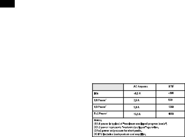
Configured at the factory for 120V or 240V nominal, 50/60 Hertz
Factory supplied cordset: Neutrik Powercon on 10’ (3m) #18AWG 120V North American cordset
20.5” (521mm) W, 35.0” (889mm) H, 18.0” (457mm) D
Allow for 4.0” (100mm) of free space behind the enclosure to assure proper amplifier cooling
99 lb/44.9 kg |
100 lb/45.4 kg |
Wear resistant textured paint finish with powder-coated perforated steel grill, black colored enclosures are supplied with handles and white colored enclosures are not
supplied with handles. 15 load-rated pick points that accept 3/8-inch, 16 threads per inch forged shoulder eye bolts.
1- Maximum Peak SPL: Calculated by adding the loudspeaker’s sensitivity (1W at 1m) to the peak power (dBw) of the amplifier provided. 2- Amplifier Power: The maximum sustained power at less than 1% clipping, averaged over the intended frequency range,
3- Input Sensitivity: The sine-wave input voltage required to reach amplifier clipping, measured within the frequency range used to determine Maximum Peak SPL, with the gain on “normal” and no gain reduction due to limiting.
104- Input Headroom/Clipping: Maximum input voltage.
5- Input Connector/Impedance: RF shunt capacitance should not reduce impedance by more than 30% at 20k Hz.
Specifications |
MD-SP215 |
MD-SP218 |
Frequency Response, ±3dB |
27-100 Hz |
26-100 Hz |
|||||||||||||||||
Frequency Range, -10dB |
25-110 Hz |
24-110 Hz |
|||||||||||||||||
Maximum Peak SPL |
131.5dB |
|
|
|
|
|
|
|
|
|
|
|
132.5dB |
|
|
||||
Transducer Description |
Two 15-in. (381mm) long-throw woofers |
Two 18-in. (457mm) long-throw woofers |
|||||||||||||||||
|
4-in. (102mm) voice coil with |
4-in. (102mm) voice coil with |
|||||||||||||||||
|
aluminum demodulating ring |
aluminum demodulating ring |
|||||||||||||||||
Amp Power |
1400 Watts |
1400 Watts |
|||||||||||||||||
Input Sensitivity |
1.2Vrms |
(+4dB) |
1.2Vrms |
(+4dB) |
|||||||||||||||
Input Headroom/Clipping |
7.5Vrms |
(+19.5dB) |
7.5Vrms |
(+19.5dB) |
|||||||||||||||
Input Connector/Impedance |
XLR female, 20k ohm balanced |
XLR female, 20k ohm balanced |
|||||||||||||||||
Output Connector |
XLR male, wired in parallel |
XLR male, wired in parallel |
|||||||||||||||||
|
with Input connector |
with Input connector |
|||||||||||||||||
Controls, Indicators, and |
Gain control, 100 Hz Hi-cut filter switch, Clip/Limit (red LED), Signal |
||||||||||||||||||
Adjustments |
presence (green LED), AC Power (blue LED) |
|
|
|
|||||||||||||||
Protection, Agency certs. |
Thermal limiting, On/Off muting, AC in-rush current limiting (<12A peak) |
||||||||||||||||||
|
FCC class B (conducted and radiated emissions), UL/CE listed |
||||||||||||||||||
AC Power Requirements |
Configured at the factory for 120V or 240V nominal, 50/60 Hertz |
||||||||||||||||||
|
|
|
|
|
|
|
|
|
|
|
|
|
|
|
|
|
|
|
|
|
|
|
|
|
|
|
|
|
|
|
|
|
|
|
|
|
|
|
|
|
|
|
|
|
|
|
|
|
|
|
|
|
|
|
|
|
|
|
|
|
|
|
|
|
|
|
|
|
|
|
|
|
|
|
|
|
|
|
|
|
|
|
|
|
|
|
|
|
|
|
|
|
|
|
|
|
|
|
|
|
|
|
|
|
|
|
|
|
|
|
|
|
|
|
|
|
|
|
|
|
|
|
|
|
|
|
|
|
|
|
|
|
|
|
|
|
|
|
|
|
|
|
|
|
|
|
|
|
|
|
|
|
|
|
|
|
|
|
|
|
|
|
|
|
|
|
|
|
|
|
|
|
|
|
|
|
|
|
|
|
|
|
|
|
|
|
|
|
|
|
|
|
|
|
|
|
|
|
|
|
|
|
|
|
|
|
|
|
|
|
|
|
|
|
|
|
|
|
|
|
|
|
|
|
|
|
|
|
|
|
|
|
|
|
|
|
|
|
|
|
|
|
|
|
|
|
|
|
|
|
|
|
|
|
|
|
|
|
|
|
|
|
|
|
|
|
|
|
|
|
|
|
|
|
|
|
|
|
|
|
|
|
|
|
|
|
|
|
|
|
|
|
|
|
|
|
|
|
|
|
|
|
|
|
|
|
|
|
|
|
|
|
|
|
|
|
|
|
|
|
|
|
|
|
|
|
|
|
|
|
|
|
|
|
|
|
|
|
|
|
|
|
|
|
|
|
|
|
|
|
|
|
|
|
|
|
|
|
|
|
|
|
|
|
|
|
|
|
|
|
|
|
|
|
|
|
|
|
|
EN
AC Power Connector |
Factory supplied cordset: Neutrik Powercon on 10’ (3m) #18AWG 120V North American cordset |
|
Dimensions |
23.3” (591mm) D |
24.0” (610mm) D |
|
26.0” (660mm) H |
28.0” (711mm) H |
|
40.0” (1016mm) W |
48.0” (1219mm) W |
|
Allow for 4.0” (100mm) of free space behind the enclosure to assure proper amplifier cooling |
|
Weight |
190 lb/86.2 kg |
210 lb/95.3 kg |
Finish and Grill |
Wear resistant textured paint finish with powder-coated perforated steel grill, black |
|
|
colored enclosures are supplied with handles and white colored enclosures are not |
|
supplied with handles. 16 load-rated pick points that accept 3/8-inch, 16 threads per inch forged shoulder eye bolts.
Notes:
1- Maximum Peak SPL: Calculated by adding the loudspeaker’s sensitivity (1W at 1m) to the peak power (dBw) of the amplifier provided. 2- Amplifier Power: The maximum sustained power at less than 1% clipping, averaged over the intended frequency range,
3- Input Sensitivity: The sine-wave input voltage required to reach amplifier clipping, measured within the frequency range used to determine Maximum Peak SPL, with the gain on “normal” and no gain reduction due to limiting.
4- Input Headroom/Clipping: Maximum input voltage. 11 5- Input Connector/Impedance: RF shunt capacitance should not reduce impedance by more than 30% at 20k Hz.

Warranty (USA only; other countries, see your dealer or distributor)
Disclaimer
QSC Audio Products, Inc. is not liable for any damage to any other equipment that is caused by negligence or improper installation and/ or use of this loudspeaker product.
QSC Audio Products 3 Year Limited Warranty
EN
QSC Audio Products, Inc. (“QSC”) guarantees its products to be free from defective material and / or workmanship for a period of three
(3) years from date of sale, and will replace defective parts and repair malfunctioning products under this warranty when the defect occurs under normal installation and use - provided the unit is returned to our factory or one of our authorized service stations via prepaid transportation with a copy of proof of purchase (i.e., sales receipt). This warranty provides that the examination of the return product must indicate, in our judgment, a manufacturing defect. This warranty does not extend to any product which has been subjected to misuse, neglect, accident, improper installation, or where the date code has been removed or defaced. QSC shall not be liable for incidental and/or consequential damages. This warranty gives you specific legal rights. This limited warranty is freely transferable during the term of the warranty period.
Customer may have additional rights, which vary from state to state.
In the event that this product was manufactured for export and sale outside of the United States or its territories, then this limited warranty shall not apply. Removal of the serial number on this product, or purchase of this product from an unauthorized dealer, will void this limited warranty.
Periodically, this warranty is updated. To obtain the most recent version of QSC’s warranty statement, please visit www.qscaudio.com.
Contact us at 800-854-4079 or visit our website at www.qscaudio.com.\ 1675 MacArthur Blvd., Costa Mesa, CA, 92626 USA
Main Number (714) 754-6175 or toll free (USA only) (800) 854-4079 Customer Service (714) 957-7150 or toll free (USA only) (800) 772-2834
© Copyright 2005, QSC Audio Products, Inc.
QSC® is a registered trademark of QSC Audio Products, Inc.
“QSC” and the QSC logo are registered with the U.S. Patent and Trademark Office
PowerCon® is a registered trademark of Neutrik® and the names of Neutrik® products referenced herein are either trademarks and/or service marks of Neutrik®. All trademarks are the property of their respective owners.
12

Precauciones importantes de seguridad y explicación de los símbolos
Instale de acuerdo con las instrucciones de QSC Audio Products y bajo la supervisión de un ingeniero profesional con la debida licencia.
 ¡ADVERTENCIA!
PRECAUCIÓN: PARA REDUCIR EL RIESGO DE DESCARGA ELÉCTRICA, NO QUITE LA CUBIERTA. EL INTERIOR NO CONTIENE PIEZAS A LAS QUE EL USUARIO PUEDA DAR SERVICIO. REFIERA EL SERVICIO A PERSONAL CALIFICADO.
El símbolo del rayo con una punta de flecha dentro de un triángulo equilátero tiene la intención de alertar al usuario de la presencia de voltaje "peligroso" no aislado dentro de la caja del producto, que puede ser de magnitud suficiente para constituir un riesgo de descarga eléctrica a los seres humanos.
El signo de exclamación dentro de un triángulo equilátero tiene la intención de alertar al usuario de la presencia de importantes instrucciones de operación y mantenimiento (servicio) en este manual.
1- Lea estas instrucciones.
2- Conserve estas instrucciones.
3- Observe todas las advertencias.
4- Siga todas las instrucciones.
5- ADVERTENCIA: Para prevenir incendios o descargas eléctricas, no exponga este equipo a la lluvia ni a la humedad. No use este aparato cerca del agua.
6- Límpielo sólo con un paño seco.
7- Deje una separación mínima de 4” (100mm) en la parte posterior de la caja para el enfriamiento por convección. Mantenga cualquier elemento que pudiera restringir el flujo de aire lejos de la parte posterior de la caja (por ejemplo, cortinados, telas, etc.). No obstruya ninguna abertura de ventilación. Este producto contiene un amplificador interno de potencia eléctrica que produce calor.
8- No lo instale cerca de fuentes de calor tales como radiadores, registros térmicos, estufas ni otros aparatos (inclusive amplificadores) que produzcan calor.
9- No anule ningún elemento de seguridad del enchufe polarizado o del enchufe con conexión a tierra. Un enchufe polarizado tiene dos hojas, una más ancha que la otra. Un enchufe con conexión a tierra tiene dos hojas y una patilla de conexión a tierra. La hoja ancha o el tercer terminal se proporcionan para su seguridad. Si el enchufe que se le proporciona no cabe en su tomacorriente, consulte con un electricista para reemplazar el tomacorriente obsoleto.
10Proteja el cable de alimentación para que no se camine sobre él ni se le comprima, particularmente los enchufes, los receptáculos y el punto en donde éstos salen del aparato.
11Use sólo piezas/accesorios especificados por QSC Audio Products, Inc.
12Use sólo con herraje, soportes, estantes y componentes vendidos con el aparato o por QSC Audio Products, Inc.
13Desenchufe el aparato durante tormentas eléctricas o cuando no lo vaya a usar durante periodos prolongados de tiempo. 14Refiera todo el servicio a personal calificado. Es necesario dar servicio al aparato cuando sufra algún daño, como cuando se daña el cable de alimentación eléctrica o el enchufe, cuando se derraman líquidos o caen objetos sobre el aparato, cuando éste ha estado expuesto a la lluvia o humedad, cuando no opere normalmente o cuando se haya caído.
15Antes de colocar, instalar, montar o suspender cualquier producto de altavoz, inspeccione todo el equipo físico, la suspensión, las cajas, los transductores, los soportes y el equipo asociado para detectar la existencia de daños. Cualquier componente faltante, corroído, deformado o no clasificado para carga podría reducir de manera significativa la resistencia de la instalación, colocación o arreglo. Cualquier condición de este tipo reduce gravemente la seguridad de la instalación y debe corregirse de inmediato. Utilice sólo el equipo físico clasificado para las condiciones de carga de la instalación y cualquier sobrecarga posible inesperada de poca duración. Nunca exceda el valor nominal del equipo físico ni del dispositivo.
16Consulte con un ingeniero profesional con la debida licencia con respecto a la instalación del equipo físico. Asegúrese de comprender y acatar todas las normativas locales, estatales y nacionales referentes a la seguridad y operación de equipos suspendidos.
Declaración de la FCC respecto a la interferencia
NOTA: Este equipo ha sido probado y se ha determinado que cumple con los límites de un dispositivo digital Clase B, en virtud de la parte 15 de las reglas de la FCC. Estos límites están diseñados para proporcionar protección razonable contra interferencia dañina en una instalación residencial. Este equipo genera, usa y puede irradiar energía de radiofrecuencia, y si no se instala y usa de acuerdo con las instrucciones, puede causar interferencia dañina con las comunicaciones de radio. Sin embargo, no hay garantía que no ocurrirá interferencia en una instalación en particular. Si este equipo causa interferencia dañina a la recepción de radio o televisión, lo cual se puede determinar al apagar y encender el equipo, se recomienda al usuario que trate de corregir la interferencia en una o más de las siguientes maneras:
Reoriente o reubique la antena receptora.
Aumente la separación entre el equipo y el receptor.
Conecte el equipo en un tomacorriente de un circuito diferente al cual está conectado el receptor.
Consulte al distribuidor o a un técnico experimentado de radio o TV para solicitar ayuda.
ES
13
Introducción
ES
¡Enhorabuena! Le agradecemos que haya comprado este producto profesional de altavoz alimentado. Para aprovechar al máximo su inversión, recomendamos que revise toda la información provista en este Manual del usuario.
Los altavoces autoalimentados de diseño modular (o “MD”) brindan una calidad de sonido excelente, una amplificación de potencia incorporada y un sinnúmero de modelos con un diseño común de cajas para facilitar la instalación. Los múltiples puntos de suspensión y un mínimo aumento de peso en comparación con las versiones no alimentadas permiten a la serie MD alimentada resolver más desafíos de aplicación que los diseños de la competencia. Disponible en negro o blanco, son la solución perfecta para templos religiosos, centros de artes dramáticas y aplicaciones de arena que exigen soluciones de sistemas flexibles y con sonido excelente. Se suministran asas en las cajas de color negro, mientras las cajas de color blanco no tienen asas para mantener un aspecto más limpio.
Todos los modelos son autoalimentados, usando amplificadores de clase D altamente eficientes y suministros de potencia de modo conmutado. La conexión a la línea de CA es rápida y sencilla; un dispositivo de desconexión rápida Neutrik PowerCon® asegura una conexión fiable a la fuente de alimentación de CA a la vez que proporciona un cable eléctrico fácil de desconectar para brindar una mayor movilidad de la caja. El audio ingresa al altavoz autoalimentado por medio de un conector XLR con una salida XLR adicional para conexión en cadena de margarita. Las características varían según el modelo, de modo que deberá consultar las especificaciones para obtener información específica sobre cada modelo.
Se muestra el modelo MD-LP (el modelo MD-SP es similar)
1- Conmutador de filtro
2- Ajustador de ganancia
3- Indicador LED verde de señal y rojo de recorte
4- Conectores de entrada y salida XLR
5- Asas, sólo en cajas negras
6- Ventilador de enfriamiento
7- Entrada del suministro eléctrico principal de CA
8- LED indicador de potencia de color azul
9- Placa con el número de serie
10Conmutador eléctrico (conmutador del suministro eléctrico principal de CA)
¡NOTA! ¡Se suministran asas sólo en las cajas de color negro! Las cajas blancas no tienen asas.
Instalación
Hay quince (15) puntos de suspensión con clasificación de carga nominal en la caja del MD-LP y dieciséis (16) en la caja del MD-SP. Tal como se envía de fábrica, cada punto de suspensión tiene instalado un perno de cabeza plana con clasificación nominal para fuerza. Dichos pernos son componentes de la caja que soportan la carga. No desmonte estos pernos salvo para reemplazar alguno con un cáncamo de resalto forjado. Si se pierde un tornillo de cabeza plana, comuníquese con el departamento de Servicios Técnicos de QSC para obtener un reemplazo.
Asegúrese de tener instalados todos los sujetadores de los puntos de suspensión, apretados correctamente a 40 in-lb (4.519 N-m) para mantener la fuerza nominal de la caja. Las fugas de aire que surgen como consecuencia de quincallería faltante degradarán el rendimiento del altavoz.
Para la suspensión con cáncamos de resalto, use sólo cáncamos de resalto forjado de 3/8 de pulgada, con 16 roscas por pulgada, número de referencia de QSC SR-000096-00. Comuníquese con el departamento de Servicios Técnicos de QSC para obtener información completa al respecto.
Antes de colocar, instalar, montar o suspender cualquier producto de altavoz, inspeccione todo el equipo físico, la suspensión, las cajas, los transductores, los soportes y el equipo asociado para detectar la existencia de daños. Cualquier componente faltante, corroído, deformado o no clasificado para carga podría reducir de manera significativa la resistencia de la instalación, colocación o arreglo. Cualquier condición de este tipo reduce gravemente la seguridad de la instalación y debe corregirse de inmediato. Utilice sólo el equipo físico clasificado para las condiciones de carga de la instalación y cualquier sobrecarga posible inesperada de poca duración. Nunca exceda el valor nominal del equipo físico ni del dispositivo.
Consulte con un ingeniero profesional con la debida licencia con respecto a la instalación del equipo físico. Acate todas las normativas referentes a la seguridad y operación de equipos suspendidos.
14
Instalación (continuación)
Enfriamiento
El amplificador de potencia interno de este producto produce algo de calor como condición normal de operación. Deje una separación mínima de 4” (100mm) en la parte posterior de la caja para obtener una ventilación adecuada, y evite exponer el equipo a luces calientes o a la luz solar directa. Para temperaturas ambientales de menos de 104°F (40°C) el ventilador normalmente permanecerá apagado. Entre 104°F (40°C) y 122°F (50°C) el ventilador funcionará durante períodos de tiempo crecientes. Por arriba de 130°F (55°C) comenzará a funcionar la protección interna contra sobrecalentamiento. La unidad reducirá su ganancia, y posiblemente se silenciará. Si el ventilador parece estar en funcionamiento constante, trate de reducir la temperatura ambiental para asegurar un total rendimiento.
Mantenga cualquier elemento que pudiera restringir el flujo de aire lejos de la parte posterior de la caja (por ejemplo, cortinados, telas, etc.).
No instale las cajas con sus paneles posteriores expuestos a la luz solar directa. La luz solar directa calentará el módulo del amplificador y reducirá su habilidad de producir una salida completa. Instale protectores solares en caso de que aplicación lo requiera.
La temperatura ambiental máxima para lograr un rendimiento completo de acuerdo con las especificaciones es 113° F (45° C).
No instale cajas donde queden expuestas a la lluvia o a otras fuentes de agua. La caja no está diseñada a prueba de la intemperie. Las instalaciones al aire libre deben brindar protección de los elementos.
ES
Línea eléctrica de CA
Conexión a la línea principal de CA
Oriente el conector PowerCon con el receptáculo PowerCon situado en el panel posterior del altavoz. Está ranurado de modo de sólo encajar en el receptáculo cuando está correctamente alineado. Inserte el conector completamente y gire hacia la derecha hasta enganchar el mecanismo de bloqueo.
El voltaje correcto de la línea de CA se muestra en la etiqueta del número de serie que se encuentra en el panel posterior. Si se conecta un voltaje de línea incorrecto se puede dañar el amplificador o aumentar el riesgo de una descarga eléctrica.
Desconexión de la fuente principal de alimentación de CA
Para desmontar el conector, retire hacia atrás la lengüeta metálica de bloqueo y gire el conector hacia la izquierda hasta que se detenga, y luego hale del mismo para quitar el conector del receptáculo.
Conmutador eléctrico
Empuje hacia adentro la parte superior del conmutador basculante para aplicar el suministro eléctrico principal de CA al altavoz alimentado. Empuje hacia adentro la parte inferior del conmutador basculante para apagar el altavoz alimentado.
Cuando está encendido, el LED indicador de potencia de color azul y el LED indicador limitador (LIM) de color rojo se iluminarán; después de unos pocos segundos, se apagará el indicador limitador de color rojo.
LED indicador de potencia
El LED indicador de potencia de color azul se iluminará cuando el conmutador de potencia de CA se encuentra en la posición de encendido (“ON”), el cable eléctrico principal de CA está correctamente conectado y el suministro eléctrico principal de CA está funcionando de manera apropiada. El LED indicador de potencia se apagará cuando el conmutador eléctrico de CA se encuentra en la posición de apagado (“off”) o la alimentación eléctrica principal de CA se ha quitado del altavoz.
Si el indicador de potencia no se ilumina cuando el conmutador correspondiente se coloca en la posición de encendido (“on”), verifique que el cable del suministro eléctrico principal de CA esté correctamente conectado al altavoz y enchufado en el tomacorriente de CA. Verifique que el tomacorriente esté funcionando correctamente.
Si el juego de cables de la alimentación principal de CA puede repararse y el tomacorriente principal de CA está funcionando correctamente, pero el altavoz no funciona, es posible que el altavoz requiera servicio técnico. Póngase en contacto con el departamento de Servicios Técnicos de QSC.
15
Conexiones de entrada/salida
El MD tiene una entrada XLR hembra de 3 patas marcada IN (ENTRADA) y un conector de salida XLR macho marcado OUT (SALIDA). Los conectores de entrada y salida se cablean en paralelo, permitiendo la conexión de múltiples cajas como “cadena de margarita”.
Se recomiendan conexiones equilibradas para menos zumbido e interferencia de la CA, especialmente con tramos largos de cable. Las conexiones no equilibradas pueden ser adecuadas para tramos cortos de cable. La impedancia de la fuente de la señal debe ser menor de 600 ohmios.
Conexión de entrada
Inserte la entrada XLR macho en el receptáculo marcado IN. Asegúrese de que el conector esté completamente asentado. La impedancia de entrada es de 12k ohmios equilibrada o 6k ohmios no equilibrada.
Entradas equilibradas: Conecte al enchufe como se muestra.
Conectores de entrada (IN) y salida (OUT)
ES
 1= blindado (tierra)


 3= menos (-)


 2= más (+)
Entradas no equilibradas: Conecte al enchufe como se muestra. La pata 3 y la pata 1 se deben conectar con un puente como se muestra.
1= blindado (tierra)
 3= puente a pata 1 2= más (+)
Conexión de salida
Inserte el conector XLR hembra en el receptáculo marcado OUT. Conecte el otro extremo del cable al conector de entrada del siguiente dispositivo de audio corriente abajo.
Control de ganancia
El control de ganancia está empotrado y se puede ajustar con un destornillador pequeño o con una herramienta plana. Gire hacia la derecha el control de ganancia para aumentar la ganancia y hacia la izquierda para reducir la ganancia. La atenuación en dB (desde el valor máximo) se muestra en la etiqueta.
El control de ganancia está marcado en dB de atenuación. Hay 21 retenes para ajustes repetibles. Los 14 pasos superiores son de aproximadamente 1 dB cada uno, y normalmente los ajustes deben hacerse dentro de este intervalo. El intervalo menor de -14 dB no se debe usar para los niveles normales del programa, ya que se podría exceder el espacio libre de entrada, pero se puede usar para hacer pruebas a niveles reducidos. En el ajuste mínimo, la señal se corta completamente.
Conmutador de selección del filtro
Arriba del control de ganancia hay un pequeño conmutador basculante que selecciona una entrada de intervalo completo o aplica un filtro de corte alto de 100 Hz a la señal de entrada.
Ajuste de corte alto de 100 Hz (ajuste de pase bajo)
Activa un filtro de cruce interno de cuarto orden. Está diseñado para funcionar con el filtro de corte bajo de 100 Hertzios en altavoces MD alimentados de dos direcciones, formando un cruce acústicamente coincidente sin procesamiento externo.
Ajuste de intervalo completo
Utilice el ajuste de intervalo completo para aplicaciones con filtrado o procesamiento de la señal corriente arriba. Esto permite modificar el sonido de acuerdo con su gusto, usando el procesamiento de la señal. La señal de entrada debe procesarse de manera apropiada para la caja (es decir, sólo señal de baja frecuencia). No aplique una entrada de audio de intervalo completo ya que el circuito interno de protección de alta frecuencia puede apagar el amplificador.
16¡No aplique una señal de entrada con contenido de alta frecuencia al tener seleccionado el intervalo completo!
Conmutador de selección del filtro
Control de ganancia
LED indicador SIG (señal)
El indicador de señal (SIG) de color verde advierte al usuario de la presencia de una señal de entrada al altavoz MD.
Indicación normal:
El indicador de señal de color verde se ilumina cuando la señal de entrada excede el valor de -25 dB.
Si no hay indicación
Revise los ajustes de ganancia y aumente la ganancia si es necesario. Revise las conexiones de entrada y la fuente de audio para ver si hay señal. Si se ilumina el LED limitador (LIM) de color rojo, consulte la sección sobre el indicador limitador, más abajo.
Indicación anormal
Si el LED de señal de color verde se ilumina sin entrada de señal, puede haber oscilaciones del sistema o algún otro mal funcionamiento. Desconecte la entrada o reduzca la ganancia completamente. Si el LED de la señal de color verde permanece encendido, es posible que el amplificador necesite servicio.
LED indicador LIM (limitador)
El indicador limitador (LIM) de color rojo advierte al usuario sobre diversas condiciones anormales dentro del altavoz MD:
Luz roja brillante continua
•Indica un modo de silenciamiento protector.
•El altavoz normalmente se silencia durante varios segundos después de aplicar potencia, después de lo cual la luz debiera apagarse, debiendo poder oírse el sonido.
•Si el altavoz ingresa en el modo de silenciamiento durante la operación, se ha sobrecalentado o ha desarrollado una falla.
•El sobrecalentamiento debiera corregirse automáticamente al cabo de 1 a 2 minutos, después de lo cual el sonido debe reanudarse. Consulte más abajo donde encontrará una explicación detallada de la protección térmica.
•Los períodos breves de silenciamiento podrían indicar un programa de alta frecuencia excesiva con el subwoofer fijado en el ajuste de intervalo completo. De no ser así, podría indicar una falla del componente; desconecte el suministro de CA y haga reparar el altavoz.
Centelleos rojos brillantes momentáneos
•Durante la operación, un centello brillante indica que hay recorte (distorsión por sobreexcitación).
•Esto se debe normalmente a un volumen excesivo, y probablemente estará acompañado por una distorsión audible.
•Si el altavoz se silencia repetidamente durante los picos, puede existir una falla de un componente. Debe desconectarse la alimentación de CA y prestarse servicio al altavoz.
Luz semibrillante continua
•Indica que el limitador interno está reduciendo la ganancia, debido a un recorte prolongado y/o una temperatura excesiva.
•Después de varios segundos de recortes importantes, el limitador reducirá la potencia para proteger el altavoz y mejorar el sonido. Esto resulta en una indicación roja semibrillante, encendida de manera permanente. Cualquier recorte adicional aún resultará en centelleos brillantes además de la indicación semibrillante permanente. Cuando se reduce el nivel del programa, el limitador se borrará después de varios segundos, y se apagará el indicador rojo.
•Si se sobrecalienta el módulo de potencia a pesar de la operación del ventilador, la primera respuesta será activar la limitación, reducir el volumen y limitar un aumento ulterior de la temperatura. Esto resulta en una iluminación semibrillante permanente que no se apaga incluso después de reducir el nivel del programa. Puede demorar varios minutos para que disminuya la temperatura y se anule el limitador. Durante este período, el sumidero térmico expuesto se sentirá incómodamente caliente al tacto y el ventilador debe estar en funcionamiento. Si continúa el sobrecalentamiento, el amplificador finalmente se silenciará, resultando en una indicación roja totalmente brillante. Al finalizar el silenciamiento, el amplificador reanudará su operación, con la limitación térmica aún activa hasta un ulterior enfriamiento.
•El sobrecalentamiento por lo general es causado por una temperatura ambiente excesiva, dado que el aumento de temperatura interna en el módulo de potencia de clase D es relativamente bajo. Proteja el altavoz de temperaturas excesivas, tales como colocarlo sobre una salida de calefacción o permitir que la luz solar directa caliente la superficie del sumidero térmico.
LED indicador
SIG (señal)
ES
LED indicador LIM (limitador)
17
Loading...