


Integrated, Self-Powered—Self-Processed, Industrial Systems
User Manual
ISIS 215SB
2 x 15” Weather-Resistant Subwoofer Cabinet with Speakon™ Input Connector
ISIS 215PCM
3000 Watt Powered Subwoofer and 3600 Watt, 2-channel “Top Box” amplifier, Computer Configurable DSP for each Amplifier, Integral Wheels and Handles.
*TD-000105-00* 1
TD-000105-00 rev.B

IMPORTANT SAFETY PRECAUTIONS & EXPLANATION OF SYMBOLS
1- Read these instructions.
2- Keep these instructions.
3- Heed all warnings.
4- Follow all instructions.
5- Do not use this apparatus near water.
6- Clean only with a dry cloth.
7- Do not block any ventilation openings. Install in accordance with QSC Audio Product’s instructions.
8- Do not install near any heat sources such as radiators, heat registers, stoves, or other apparatus (including amplifiers) that produce heat.
9- Do not defeat the safety purpose of the grounding-type twist-lock NEMA L5-30 AC power connections. The polarized, locking plug has one blade that is shaped differently than the others. This ensures that the plug can only be inserted correctly. If the provided plug does not fit your outlet, consult an electrician for the replacement or installation of a proper outlet.
10Protect the power cord from being walked on or pinched, particularly at plugs, convenience receptacles, and the point where they exit the apparatus.
11Only use attachments/accessories from QSC Audio Products, Inc.
12Use only with stands, tripods, brackets, interconnecting cables, software specified by QSC Audio Products. 13When moving or transporting using built-in wheels or a cart, use caution to avoid injury from tip-over.
14Unplug the apparatus during lightning storms or when unused for long periods of time.
15Refer all servicing to qualified personnel. Servicing is required when the apparatus has been damaged in any way, such as power supply cord or plug is damaged, liquid has been spilled or objects have fallen into the apparatus, the apparatus has been exposed to rain or moisture, does not operate normally, or has been dropped.
The lightning flash with arrowhead symbol within an equilateral triangle is intended to alert the user to the presence of uninsulated “dangerous” voltage within the product’s enclosure that may be of sufficient magnitude to constitute a risk of electric shock to humans.
The exclamation point within an equilateral triangle is intended to alert the user to the presence of important operating and maintenance (servicing) instructions in this manual.
WARNING! Before placing, installing, rigging, or suspending any speaker product, inspect all hardware, suspension, cabinets, transducers, brackets and associated equipment for damage. Any missing, corroded, deformed or non-load rated component could significantly reduce the strength of the installation, placement, or array. Any such condition severely reduces the safety of the installation and should be immediately corrected.
Use only hardware which is rated for the loading conditions of the installation and any possible short-term unexpected overloading. Never exceed the rating of the hardware or equipment. Consult a licensed, professional engineer when any doubt or questions arise regarding a physical equipment installation.
The 215PCM has a serial number located on its rear panel, next to the AC entry.
The 215SB has a serial number located on its Speakon™ entry panel.
Please write this and the model number down and keep them for your records.
Model: ISIS 215 _______________________
Serial Number:________________________
Date of Purchase: ______________________
Purchased From:_______________________
© Copyright 2002, QSC Audio Products, Inc.
QSC® is a registered trademark of QSC Audio Products, Inc.
“QSC” and the QSC logo are registered with the U.S. Patent and Trademark Office All trademarks are the property of their respective owners.
Speakon™ is a registered trademark of Neutrik Inc., Lakewood, NJ
2

TABLE OF CONTENTS
INTRODUCTION |
|
General Overview........................................................................................... |
4 |
Technical Overview........................................................................................ |
6 |
Block Diagram................................................................................................. |
7 |
UNPACKING |
|
Unpacking and Inspection.................................................................................. |
8 |
What is Included............................................................................................. |
8 |
WHERE DO I START?................................................................................................... |
9 |
PREPARATION FOR FIRST USE |
|
Amplifier Gain Controls.......................................................................... |
10 |
CONNECTIONS |
|
AC Power....................................................................................................... |
11 |
Processor RS-232...................................................................................... |
12 |
Mode Switch..................................................................................... |
13 |
XLR Audio Inputs.............................................................................. |
14 |
Post-Processor Outputs................................................................... |
16 |
DataPorts................................................................................... |
17 |
Outputs.............................................................................................. |
18 |
USE |
|
Cooling Air Intake and Exhaust Vents........................................................... |
19 |
AC Power Switch and LED Indicators............................................................ |
20 |
Important User Warning Regarding Power Levels................................... |
21 |
System Requirements and Software Installation......................................... |
22 |
General Guidelines for Freely-Configurable DSP....................................... |
23 |
Saving Presets.............................................................................................. |
24 |
Configuring the Processors (examples of Signal Manager software)....... |
25 |
TROUBLESHOOTING................................................................................... |
28 |
SPECIFICATIONS |
|
215SB Dimensions........................................................................................ |
31 |
215SB Acoustic Performance..................................................................... |
32 |
215SB Specifications................................................................................... |
33 |
215PCM Dimensions...................................................................................... |
34 |
215PCM Specifications................................................................................. |
35 |
215PCM Power Amplifier‘s Specifications......................................................... |
36 |
215PCM Digital Signal Processor’s Specifications........................................ |
37 |
APPENDIX |
|
Contact Closure Wiring................................................................................... |
38 |
RS-232 Pinout.............................................................................................. |
39 |
WARRANTY INFORMATION ............................................................................................. |
40 |
HOW TO CONTACT QSC AUDIO PRODUCTS ......................................................... |
40 |
3

INTRODUCTIONGeneral Overview
Introduction
Thank you and congratulations on your purchase of the ISIS 215PCM Powered-System Control Module or 215SB Subwoofer. This product represents the state-of-the-art in all-weather, lightweight SR (sound reinforcement) loudspeaker systems. The “215” marks the introduction of QSC’s ISIS loudspeaker systems. ISIS is short for Integrated, Self-Powered—Self Processed, Industrial Systems. To get the most from your investment, we encourage you to review this manual carefully.
The 215PCM is a self-contained active subwoofer system with dual 15-inch drivers. It provides power amplification not only for itself, but also two channels for driving fullrange or biamp “top box” speakers as well. It is the most advanced core module for portable live sound reinforcement systems and is ideal for corporate and industrial events. The 215SB is a passive subwoofer system with no backpack electronics, equipped with a single Speakon™ connector.
215SB Subwoofer Highlights
Composilite™
QSC enclosures incorporate Composilite, a patented cored composite technology that yields superior acoustic properties, lighter weight, and greater weather resistance compared to conventional enclosure materials. Multiple skins of carbon fiber are layered over a honeycomb core to form a rigid, seamless enclosure. The extreme stiffness of Composilite construction prevents flexing of the cabinet enclosure, significantly reducing energy loss due to cabinet vibration. The result is reduced enclosure loss, increased low frequency output, and substantially less sound radiating from the back and sides of the enclosure for greater sonic accuracy. Furthermore, the enclosure’s light weight translates to safer rigging and reduced handling costs.
The frequency response of the 215PCM is 35 to 150 Hz (-3 dB). Two 15-inch, diametrically opposed (facing each other) drivers fire in opposite directions with equal excursion. The net effect being the driver forces counterbalance, minimizing vibration in the cabinet. This is essential in lightweight, ultra-stiff cabinet designs to keep the walls from vibrating excessively and to keep the cabinet from “walking away” during use.
215PCM Powered Control Module Highlights
The “PCM” version adds a 55 pound amplification and signal processing backpack to the 215SB subwoofer cabinet. This backpack houses two independent power amplifiers, one for the subwoofer and one for the “top boxes”. Driving the subwoofer is the equivalent of a bridged-mode PL230 amplifier providing up to 3000 watts to the two 15-inch drivers. Top boxes are powered by the equivalent of a PL236 amplifier (725 W/ch. @8 ohms, 1100 W/ch. @ 4 ohms, 1850 W/ch. @ 2 ohms). Signal processing is provided by two DSP-3 Digital Signal Processors with 24-bit, 48 kHz. convertors. Both processors have eight userconfigurable and -selectable presets. An RS-232 connection to a PC running the provided QSC Signal Manager Software enables system tuning and configuration.
4
INTRODUCTIONGeneral Overview
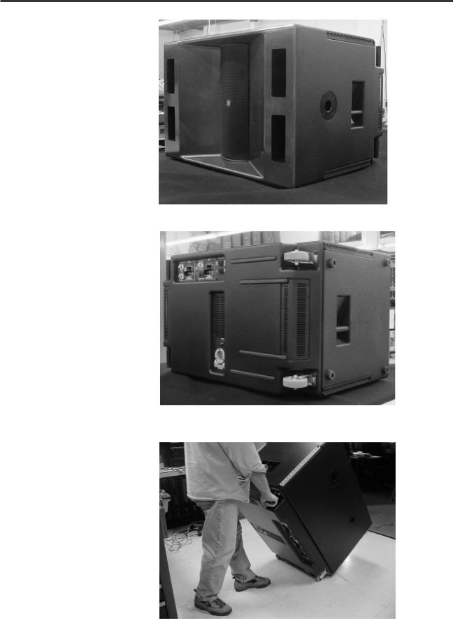
215PCM Front
A 16” length of “L-track” flying hardware is featured on all four corners of the cabinet.
Pole cups are featured for either cabinet orientation. One, shown, on the shorter side, and two on the longer.
215PCM Rear
Rubber feet are featured on the bottom of the cabinet, as viewed, and on the end in cases where it is desired to stand the cabinet up.
The four hard-rubber strips (on the right of the cabinet) provide protection to the cabinet back when moving up or down stairs and curbs.
Transporting the 215PCM using integral wheels and handles.
5

INTRODUCTIONTechnical Overview
Technical Overview:
CH1 and CH2 Inputs are connected to the Top Box Processor and to the Mode Switch. In Combination Mode, the Mode Switch connects CH1 and CH2 Inputs to the Subwoofer Processor as well. In Discrete Mode, CH1 and CH2 Inputs are disconnected from the Subwoofer Processor, and Input 3 is used to feed the Subwoofer Processor.
Independent DSP is provided for each amplifier. The DSP engines are 24-bit resolution, 48 kHz. sampling rate. They boast less than 0.01% THD+N, 20 Hz. -20 kHz. ±0.7dB frequency response and a dynamic range exceeding 93 dB. All that is required is configuring the Processors with the desired signal chain before use.
Each Processor must be configured using QSC’s Signal Manager software, included with the 215PCM. Install the software on a PC meeting the specified system requirements, then connect to the Processors (one at a time) with an RS-232 connection and run Signal Manager. Each Processor has 8 Preset memories enabling the most used configurations to be saved as convenient, easy to recall Presets. The last applied configuration will be the power-on default, ensuring the system powers-up in the state it was last left. Refer to the software’s on-line Help system for detailed information. All software related operation information is located in Signal Manager’s Help system.
The Top Box Processor’s OUT1 and OUT2 DSP ports are connected to the 3600 watt Top Box amplifier’s CH1 and CH2 Inputs, respectively. The Top Box amplifier is configured to operate in stereo mode without any filtering. All filtering and is done in the Processor.
The Subwoofer Processor’s OUT1 DSP port is connected to the Subwoofer amplifier’s CH1 Input. The Subwoofer amplifier is operated in Bridge Mode. The amplifier has no filtering. All desired processing must be done in the Processor. The Bridge Mono outputs are wired internally to the subwoofers.
Post Processor output connections are provided on each Processor. These 3-pin terminal block connectors make daisy-chaining the processed signal to other equipment a snap.
The amplifiers are modified QSC Powerlight2 models. They feature PowerWave™ high frequency switching power supplies for maximum performance and minimum weight. Gain controls are preset to full, but each amplifier’s Gain controls are accessible through small access holes in the respective cooling air intake grill; this allows a relatively tamper-proof maximum gain setting. The amplifiers provide features such as soft-start inrush current limiting, tempera- ture-tracking bias control, variable speed cooling fans, and full output protection.
A variety of Top Box speakers are connected to the Speakon™ connectors on the rear panel. The upper Speakon is wired for optional biamp use (4-wire), and the lower Speakon is wired normally (2-wire). This connection scheme allows for biamp users to plug into one connector for all four biamp wires, while still keeping the standard two Speakons for two channel applications.
6

INTRODUCTIONBlock Diagram
7

UNPACKING
Unpacking and Inspection
The 215PCM is highly durable and is carefully packaged and crated. We recommend you inspect the unit carefully after removing it from the packaging, as occasionally there may be damage due to some unfortunate incident during shipment. Report any damage to the shipping carrier. We recommend saving the carton and packing material. It is always a good idea to keep the packaging in case the unit must be shipped back to your dealer, distributor, or service center. Also note: some freight companies consider damage claims without the original packing materials invalid.
When removing the loudspeaker from its packaging, grasp the unit using the integral handles on the sides. The transducers are deeply recessed and covered with a strong metal grill, requiring no extra care. Care is required in the control panel area on the rear of the cabinet. Be sure not to damage any switches or connectors.
The QSC shipping box should contain:
1- The 215PCM system or 215SB cabinet
2- This Owner’s Manual
3- Power Cord: 120 Volt, 30 Amp, 3 feet long (215PCM only) 4- QSC Signal Manager Software CD
WHERE DO I START?
For 215SB Subwoofer Only Users-
1- |
Plug in your Speakon connection to the cabinet and use as any other passive subwoofer cabinet. |
2- |
Refer to pages 3133 for Specifications and Performance Data. |
8

WHERE DO I START?
For 215PCM Powered Core Module Users-
1-
2-
Install the Signal Manager software on the PC that will be used to configure the 215PCMs processors. See page 20.
Put the 215PCM in a location that: |
• |
....is close enough to the PC to connect the serial cable. |
|
•....has 120V, 30A service to power the 215PCM. |
|
|
•.... |
has enough room to make connections or adjustments. |
3- |
Plug in the 215PCM. See page 11. |
4- |
Connect the serial cable from the PC’s COM port to the Top Box Processor. See page 12. |
5- |
Turn on the 215PCM. |
6- |
Open the Signal Manager software on the PC. Signal Manager should read the configuration data for the processor you are |
|
connected to and indicate ONLINE in its status window. If it does not, verify the correct COM port is selected using Signal |
|
Manager’s Settings/DSP pull-down menu. See the Troubleshooting page 29 of this manual for more help if your PC can’t |
|
communicate with your 215PCM’s Processor. |
7- |
Configure the Top Box Processor as required for your application. Apply the configuration and save it. Click the ONLINE/ |
|
OFFLINE icon in the software; wait for the Status Indicator at the bottom of the Signal Manager window to indicate OFFLINE. |
|
It is now safe to move the RS-232 connection from one processor to the other. |
8- |
Move the RS-232 connection from the Top Box Processor to the Subwoofer Processor being sure to connect properly. Click |
|
the ONLINE/OFFLINE icon in the software. The Status Indicator will show ONLINE now. The configuration currently running in |
|
the Subwoofer Processor will be displayed. This will take a few moments. |
9- |
Configure the Subwoofer Processor as required by your application. Apply the configuration and save it. Click the ONLINE/ |
|
OFFLINE icon in the software; once OFFLINE is indicated, disconnect your Processor. |
10- |
Set the MODE SWITCH in COMBINATION or DISCRETE MODE as required by the application. See page 13. |
11- |
Connect the Top Box Speakers to the Top Box Outputs. See page 18. |
|
•“Passive” Connection: Connect the two Top Box speakers to the two Output connectors |
|
•“Active/Biamp” Connection: If using a 4-wire biamp connection (Neutrik NL4) use only the top Speakon. |
|
Both channels are connected to the upper Speakon as noted next to the connector. |
12- |
Test your system and alter your processing if you need to. |
9
PREPARATION FOR FIRST USEAmplifier Gain Controls
Adjusting the Gain Settings of the Amplifiers
Ordinarily, the Gain controls of the amplifiers are left set at full gain. This is not recommended for first-time users of freelyconfigurable DSP. Freely configurable DSP, while being the most flexible and desirable, will do precisely what the user configures it to do. This may not be the expected, desired result and could damage your speakers or hearing. For this reason, QSC recommends the initial “learning” sessions with the 215PCM be carried out with the amplifier Gain controls set at their minimum useful settings.
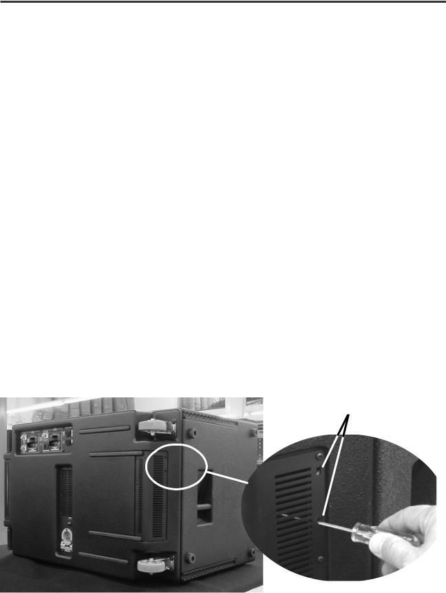
Each of the two cooling air exhaust vents (one on each end of the cabinet) has two small, rectangular openings for adjusting the Gain controls. The exhaust vent closest the wheels has the access holes for the Subwoofer amplifier. The exhaust vent closest the handles has the access holes for the Top Box Amplifier.
Below, the illustration shows the location of the Subwoofer amplifier’s gain adjustment access holes. The Top Box amplifier’s access holes are on the vent located on the other end of the cabinet (left, as viewed). The access holes are not labeled. This is to discourage gain tampering after the 215PCM is set up. Use a 6- inch #1 flat blade screwdriver or similar tool. Fiberglass-shaft TV adjustment tools work well, are nonconductive, and won’t scratch equipment easily. Use a flashlight to aid in locating the gain control.
Gain control adjustment access holes (Subwoofer amplifier shown). The lower hole accesses CH1’s gain control. CH2’s gain control has no effect because the Subwoofer amplifier is configured in bridge mono mode at the factory. Access is available for CH2’s gain control for users that modify the 215PCM. Note that modifications may void warranty.
10
CONNECTIONSAC Power
AC Power Connection
The 215PCM requires a 120 Volt, 30 Amp connection to the AC mains. The power connectors used are to be NEMA L5-30, or equivalent. The serial number plate is imprinted with the operating voltage information.
At peak output power, the 215PCM can supply up to 6,600 watts of music power. At these levels, the AC line current can easily reach levels in excess of 20 Amps. Proper AC connections are required at such high power levels.
Connect the 30 Amp twist-lock connectors by orienting the locking L- shaped prong with the corresponding connector entry, then fully insert the three prongs. Twist the plug about 1/8 of a turn clockwise to lock
the connector and plug.
Power switch.
The 215PCM requires 120 Volt, 30 Amp AC service. Attempting full power operation on lower rated circuits may overheat wirirng and cause breakers to switch off.
Use only heavy-duty 12 or 10 ga. extension cords.
AC Power Switch
Above and to the right of the AC entry connector is the Power switch. The switch is labeled POWER ON, above it.
To turn the power on: Press in on the upper portion of the rocker switch. Both DSP-3’s blue Power indicators should illuminate.
To turn the power off: Press in on the bottom portion of the rocker switch. It may take a few moments for the Power LED’s to extinguish. This is normal.
215PCM AC connection. The keyed connector fits only one way. Align the “L” shaped tang with the mating receptacle and fully insert, then twist 1/8 turn clockwise to lock in place. Reverse procedure to remove plug.
11

CONNECTIONS- RS-232 Processor Configuration Connection
RS-232 Connection (215PCM only)
Each Processor has a 9-pin “D-sub” connector labeled RS-232. The RS-232 connection is used to configure the Processor by connecting to the PC’s COM port.
Important points:
–The 215PCM must be ON (powered up) in order to configure the Processors.
–Each Processor is configured individually.
–The serial cable connection is not required after configuring a Processor.
–Configurations are kept in the Processor’s nonvolatile memory and on the PC.
RS-232: Used to setup (or configure) the Processor. Connect to your PC’s COM port using a normal 9-pin serial data cable (25 ft. maximum length). The Signal Manager software used to create your DSP chain “talks” to the Processor through the computer’s COM port connection. Once the Processor has been configured, RS232 connection is no longer required. Any change to the Processor’s setup requires the RS-232 connection to the PC’s COM port.
To Configure a Processor (215PCM only)
1- Install the included Signal Manager software on a PC/laptop meeting the minimum system requirements. See page 22 for complete installation instructions.
2- Connect a normal 9-pin serial data cable between your PC’s COM port and the RS-232 connector of the Processor you want to set up (or configure).
3- Start the Signal Manager software and establish communication between the PC and the Processor. If the status indicator (bottom right of the Signal Manager window) shows ONLINE, the software and Processor are connected. If it does not, verify cable connections and refer to the top of page 29, Troubleshooting.
4- Use the Help system to learn how to use Signal Manager.
12
CONNECTIONSMode Switch and Signal Routing
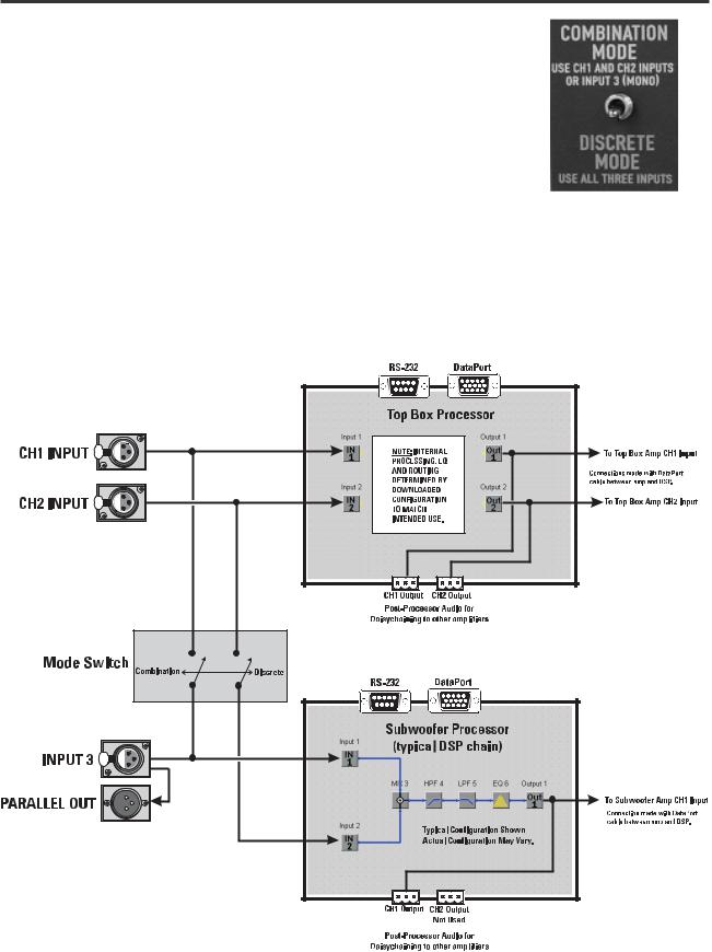
MODE SWITCH (215PCM only)
The position of the Mode Switch determines how the input signals are routed. Select your operating mode before making connections. If you are using the DataPorts for audio input, the Mode Switch has no effect. Refer to the diagram, below.
COMBINATION MODE– Use CH1 and CH2 Inputs OR Input 3 (mono).
Typical “Left-Right” mixes will provide a stereo feed for CH1 and CH2 Inputs. CH1 and CH2 Inputs will be routed to BOTH Processor’s IN1 and IN2 blocks (see diagram, below).
If only one input (mono) or one side of the mix is available, then use Input 3. Input 3 will route the input to the IN1 block.
DISCRETE MODE– Use all three inputs. CH1 Input is routed to the Top Box Processor IN1 block, CH2 Input to IN2. Input 3 is connected to the Subwoofer Processor IN1 block. Note, the Subwoofer Processor’s IN2 is not connected when operating in DISCRETE MODE.
SIGNAL ROUTING BY MODE SWITCH
The mode switch effects how
the input signals are connected
to the Processors.
13
 Loading...