


CX-12-T

31
CX Series
USER MANUAL
▼▼
▼▼
▼
CX4
▼▼
▼▼
▼
CX4T
▼▼
▼▼
▼
CX6
▼▼
▼▼
▼
CX6T
▼▼
▼▼
▼
CX12
▼▼
▼▼
▼
CX12T
Rev. B
*TD-000057-00*
*TD-000057-00**TD-000057-00*
*TD-000057-00**TD-000057-00*
*TD-000057-00*

1
T able of Contents
PART 1—CX SERIES USER MANUAL
I. Warning Notices ....................................................................................................................................... 2
Speaker Damage ............................................................................................................................................ 3
Speaker Output Shock Hazard.......................................................................................................................3
Rack Mounting Precautions...........................................................................................................................3
II. Overall Description ................................................................................................................................... 4
III. Inputs............................................................................................................................................................ 6
Input Sensitivities..........................................................................................................................................6
IV. Outputs ......................................................................................................................................................... 6
V. Controls & Displays ................................................................................................................................... 8
VI. Operation ..................................................................................................................................................... 8
AC Power ....................................................................................................................................................... 8
Operation .......................................................................................................................................................8
Troubleshooting .............................................................................................................................................9
Open Input Architecture
™
Level I................................................................................................................. 10
Parallel, Stereo, or Bridged Operation ....................................................................................................... 11
Maximum Long-Term Output Power ........................................................................................................... 13
AC Current Consumption ............................................................................................................................. 13
Heat Emissions............................................................................................................................................. 14
Protection Circuits ....................................................................................................................................... 15
VII. Specifications.......................................................................................................................................... 16
PART 2—CX APPLICATION GUIDE.................................................................................. 19
VIII. Distributed Lines ..................................................................................................................................... 19
IX. Designing the Distributed Sound System .......................................................................................... 20
Loudspeaker Coverage and Placement....................................................................................................... 20
Determining Power Levels...........................................................................................................................22
Selecting the Amplifier ...............................................................................................................................23
Using Components with Different Voltages...............................................................................................24
X. How Many Speakers? .............................................................................................................................25
XI. Other Design Considerations ................................................................................................................26
Speaker Transformer Saturation ................................................................................................................26
Connecting Both a Distributed Line and a Direct Loudspeaker on One Channel...................................... 26
Wire Loss .....................................................................................................................................................27
AC Current Consumption ............................................................................................................................. 29
Heat Emissions............................................................................................................................................. 29
XII. Address & Telephone Information ......................................................................................................30
2
EXPLANATION OF GRAPHICAL
SYMBOLS
The lightning flash with arrowhead
symbol, within an equilateral triangle,
is intended to alert the user to the
presence of uninsulated “dangerous
voltage” within the product’s enclo-
sure that may be of sufficient magni-
tude to constitute a risk of electric
shock to humans.
The exclamation point within an equi-
lateral triangle is intended to alert
the users to the presence of impor-
tant operating and maintenance (ser-
vicing) instructions in the literature
accompanying the product.
CAUTION: To reduce the risk of electric shock, do not
remove the cover. No user-serviceable parts inside.
Refer servicing to qualified service personnel.
WARNING: To prevent fire or electric shock, do not
expose this equipment to rain or moisture.
CAUTION
RISK OF ELECTRIC SHOCK
DO NOT OPEN
ATTENTION: Pour eviter les risques de choc électrique,
ne pas enlever le courvercle. Aucun entretien de
pièces intérieures par l’usager. Confier l’entretien
au personnel qualifié.
AVIS: Pour eviter les risques d’incendie ou
d’électrocution, n’exposez pas cet article à la pluie
ou a l’humidité.
AVIS
RISQUE DE CHOC ÉLECTRIQUE
NE PAS OUVRIR
VORSICHT: Um das Risiko eines elektrischen Schlages
zu vermindern, Abdeckung nicht entfernen! Keine
Benutzer Wartungsteile im Innern. Wartung nur durch
qualifiertes Wartungspersonal.
WARNUNG: Zur vermeidung von Feuer oder
elektrischen Schlägen, das Gerät nicht mit Regen
oder Feuchtigkeit in Berührung bringen!
VORSICHT
GEFAHR EINES ELEKTRISCHEN
SCHLAGES. NICHT ÖFFNEN!
SAFEGUARDS
Electrical energy can perform many useful func-
tions. This unit has been engineered and manufac-
tured to assure your personal safety. Improper use
can result in potential electrical shock or fire hazards.
In order not to defeat the safeguards, observe the
following instructions for its installation, use and
servicing.
PRECAUTIONS
L’énergie électrique peut remplir de nombreuses
fonctions utiles. Cet appariel a été conçu et réalisé
pour assurer une sécurité personnelle entiére. Une
utilisation impropre peut entraîner des risques
d’électrocution ou d’incendie. Dans le but de ne pas
rendre inutiles les mesures de sécurité, bien ob-
server les instructions suivantes pour l’installation,
l’utilisation et l’entretien de l’appareil.
EXPLICATION DES
SYMBOLES GRAPHIQUES
Le symbole éclair avec point de flèche
à l’intrérieur d’un triangle équilatéral
est utilisé pour alerter l’utilisateur de
la presence à l’intérieur du coffret de
“voltage dangereux” non isolé
d’ampleur suffisante pour constituer
un risque d’elétrocution.
Le point d’exclamation à l’intérieur
d’un triangle équilatéral est employé
pour alerter les utilisateurs de la
présence d’instructions importantes
pour le fonctionnement et l’entretien
(service) dans le livret d’instruction
accompagnant l’appareil.
ERKLÄRUNG DER GRAPHISCHEN
SYMBOLE
Der Blitz nach unten zeigendem Pfeil in
einem gleichseitigen Dreieck weist den
Benutzer auf das Vorhandensein einer
unisolierten,
”
gefährlichen
Spannung“ im Gehäuse hin, die stark
sein kann, einer Person einen
elektrischen Schlag zu versetzen.
Das Ausrufzeichen in einem
gleichseitigen Dreieck weist den
Benutzer auf wichtige Betriebs- und
Wartungs- vorschriften in den
beiliegenden Unterlagen des Gerätes
hin.
DECLARATION OF CONFORMITY
for all CX and CXT models
We declare as our sole responsibility
that this product is in compliance with
the EMC Directive 89/336/EEC and con-
forms to the requirements of the Har-
monized Product Standards EN 55013
(Product Emissions), and EN 55020
(Product Immunity).

3
I. Warning Notices
SPEAKER DAMAGE
The CX Series amplifiers are among the most powerful professional amplifiers available and are capable of
producing much more power than many loudspeakers can handle. It is the user’s responsibility to use suitable
speakers with the amplifier and to use them in a sensible way that will not cause damage.
QSC will not be responsible for blown speakers. Consult the speaker manufacturer for power-handling
recommendations.
Even if you reduce the gain using the amplifier’s rear panel attenuator controls, it is still possible to reach full
output power if the input signal level is high enough.
A single high-power crescendo can blow high-frequency speaker drivers almost instantaneously, while low-
frequency drivers can usually withstand very high, continuous power levels for a few seconds before they too
die. Reduce power immediately if you hear any speaker “bottoming out”-harsh pops or cracking distortion that
indicate that the speaker voice coil or diaphragm is striking the magnet assembly.
QSC recommends that you use amplifiers of this power range for more headroom (cleaner sound) rather than
for increased volume.
SPEAKER OUTPUT SHOCK HAZARD
A CX amplifier is capable of producing hazardous output voltages. To avoid electrical shock, make sure the cover
is in place over the output terminals, and do not touch any exposed speaker wiring while the amplifier is operating.
RACK MOUNTING PRECAUTIONS
To minimize twisting stress on the front mounting ears, the amplifier’s internally mounted output transformers
are located close to the front panel. Nevertheless, when rack mounting any CX amplifier, make sure it is well
supported at all four corners to avoid damage to either the amplifier mounting ears or the mounting rails.
Contact the QSC Technical Services Department to order rear support brackets.
LIFTING PRECAUTIONS
In order to safely move or install the amplifier, it is recom-
mended that two persons share the weight when lifting and
positioning the unit.
SICHERHEITSVORSCHRIFTEN BEIM HOCHHEBEN
Um den Verstärker sicher zu verschieben oder einzubauen,
wird empfohlen, das Gewicht des Verstärkers beim Hochheben
und Verschieben gleichmäßig auf zwei Personen zu verteilen.
Optional rear rack
mounting ears.
4
II. Overall Description
The CX Series from QSC comprises six high-efficiency professional power amplifier models, each with two
independent channels. The table below lists the range’s audio power ratings.
Each channel has its own power transformer secondary. The CX4, CX4T, CX6 and CX6T utilize complementary
Class AB linear output circuitry. For improved efficiency, the CX12 and CX12T utilize Class H step linear
complementary output circuitry and have bipolar multi-rail power supplies. The power transformers, as are the
output transformers, are mounted in the front of the amplifier chassis, as close to the front mounting rails as
possible; this keeps the unit’s center of gravity forward to minimize the twisting force on the front
mounting ears. Still, the amplifier should be supported at all four corners, especially if it is in a
portable rack.
The CX4 and CX4T are two rack spaces high; the CX6, CX6T, CX12, and CX12T are three rack spaces
high. The adjacent table lists the amplifiers’ weights by model.
The amplifiers require a rack depth of 18 inches (45.7 cm) to clear the rear support ears. Allow
some additional clearance for input and output connectors at the rear panel, which is 16.9 inches
(42.9 cm) behind the plane of the frount mounting rails. The built-in cooling fan draws air in at
the rear of the chassis and exhausts it through vents in the front panel. The flow-through cooling
scheme allows you to rack-mount the amplifiers one atop the other, with no clearance necessary
in between. This mounting technique also helps support the weight of the upper amplifiers.
The CX Series derives much of its design from our award-winning MXa Series amplifiers. They are engineered
for stability and exceptional reliability, with protection for open or short circuits and mismatched loads. To protect
your loudspeakers, the outputs mute during turn-on and turn-off, and also in the event of a DC fault. The CX4
and CX4T are AC coupled and cannot pass DC to the load. Therefore, the DC fault muting is not required. All
protection circuitry automatically resets to normal when conditions assure safe operation.
Every CX amplifier features thermal management and protection in the form of a two-speed fan and extruded
aluminum heat sinks with direct-mounted output devices. If a heat sink overheats to 85½ C or higher, a protection
circuit mutes the amplifier channel output.
MODEL NET WEIGHT
CX4 13.6 kg; 27 lb
CX4T 18.2 kg; 37 lb
CX6 20 kg; 42 lb
CX6T 25 kg; 55 lb
CX12 22.7 kg; 50 lb
MODEL 8
ΩΩ
ΩΩ
Ω
1
4
ΩΩ
ΩΩ
Ω
1
2
ΩΩ
ΩΩ
Ω
2
25 volts
3
70 volts
1
100 volts
1
CX4 150 watts 225 watts 350 watts
CX4T 150 watts 225 watts 350 watts 150 watts
4
175 watts
4
175 watts
4
CX6 200 watts 300 watts 450 watts
CX6T 200 watts 300 watts 450 watts 200 watts
3
250 watts
3
250 watts
3
CX12 425 watts 600 watts 900 watts
CX12T 425 watts 600 watts 900 watts 400 watts
3
500 watts
3
500 watts
3
1: FTC watts per channel, 20 Hz–20 kHz, 0.1% THD
2: EIA watts per channel, 1 kHz, 1% THD
3: Watts per channel, 45 Hz-15 kHz, 0.25% THD
4: Watts per channel, 50 Hz-15 kHz, 0.25% THD

5
2 4112
Front
features of
CX6, CX6T,
CX12 or
CX12T
amplifier
2 3 4 5
112
109
7 78 14
6 11
10 11
13
109
7 78
6
14
13
Front
features of
CX4 or CX4T
amplifier
1 — Power Switch
2 — Power Indicators (Ch1, Ch2)
3 — Signal Indicators (Ch1, Ch2)
4 — Clip Indicators (Ch1, Ch2)
5 — Protect Indicators (Ch1, Ch2)
6 — Accessory Slot Cover
7 — Gain Control
8 — Detachable Input Header
9 — Cooling Fan
10 — Shrouded Output Connector
(Direct Outputs)
11 — Shrouded Output Connector
(Isolated Outputs)
12 — Mounting Holes for
Optional Handles
13 — Rear Support Ear
14 — Parallel/Stereo/Bridge
Switch
Rear
features of
CX4
amplifier
Rear features
of CX4T
amplifier
109
7 78
13
109
7 78
11 10 11
13
Rear features
of CX6T or
CX12T
amplifier
Rear
features of
CX6 or CX12
amplifier
6
Channel 2+
Channel 2-
Ground
Ground
Ground
Channel 1-
Channel 1+
Loosen screw,
insert wire here,
then tighten screw.
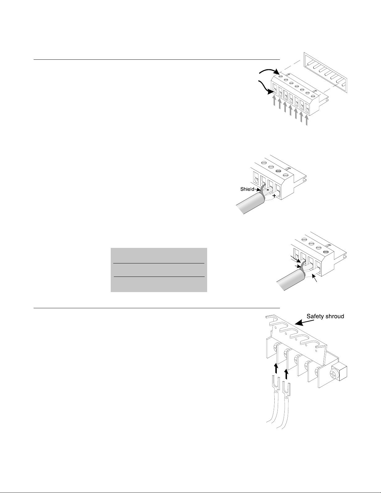
III. Inputs
CX amplifiers feature balanced inputs, connected via a Euro-style 7-terminal
detachable header. Attach input signal wires as shown. If you are connecting an
unbalanced signal to an input, use the non-inverting (+) input and the ground
terminals of the header, and also connect a wire jumper between the inverting (-)
input and the ground terminal. The wire jumper will prevent a reduction in gain
caused by a floating input.
If you need XLR or 1/4” RTS inputs on your CX6, CX6T, CX12, CX12T, use the optional MX-1
input expander (available through QSC’s Technical Services Department).
Typical of QSC amplifiers, the input impedance of a CX Series amplifier is 20 kilohms balanced
and 10 kilohms unbalanced.
Each CX Series (except CX4, CX4T) amplifier features a Level I Open Input Architecture slot.
See the Operation Chapter for more information about Open Input Architecture.
INPUT SENSITIVITIES
Audio signals of these levels will produce full rated output power at 8 ohms.
CX4, CX4T 0.98 volt (+2.0 dBu)
CX6, CX6T 1.02 volt (+2.4 dBu)
CX12, CX12T 1.00 volt (+2.2 dBu)
IV . Outputs
Covered barrier strips located on the rear panel allow speaker cable connections to the amplifier
outputs. See the diagrams for details on connecting speakers and/or distributed (25-, 70-, or 100-
volt) lines. For attaching wires, we recommend using insulated connectors of the type shown. Always
make sure the amplifier is turned off before you change any output connections or lift the safety
shroud.
If you are operating the amplifier in bridged mono mode to achieve higher output voltages, neither
speaker wire is grounded. Therefore, use the same precautions in handling and dressing the wire
that you would for the normal “hot” outputs. See the section on bridged mono operation for
additional important instructions.
If you are driving a distributed line, make sure the sum of all the power demands of the speakers
does not exceed the amplifier’s power rating. In fact, it is good practice to allow about a 25% safety
margin. For example, if the load on the distributed line is 400 watts, use an amplifier with a power
rating of 500 watts. See the Application Notes in the back of this manual for more details on distributed lines.
Lift safety shroud.
Loosen screw
terminals.
Insert wire connectors
under screws.
Tighten screw
terminals.
Lower safety shroud.
Balanced input
connections
Shield
Signal conductor
Wire jumper
between
input and
ground
Unbalanced input
connections
7
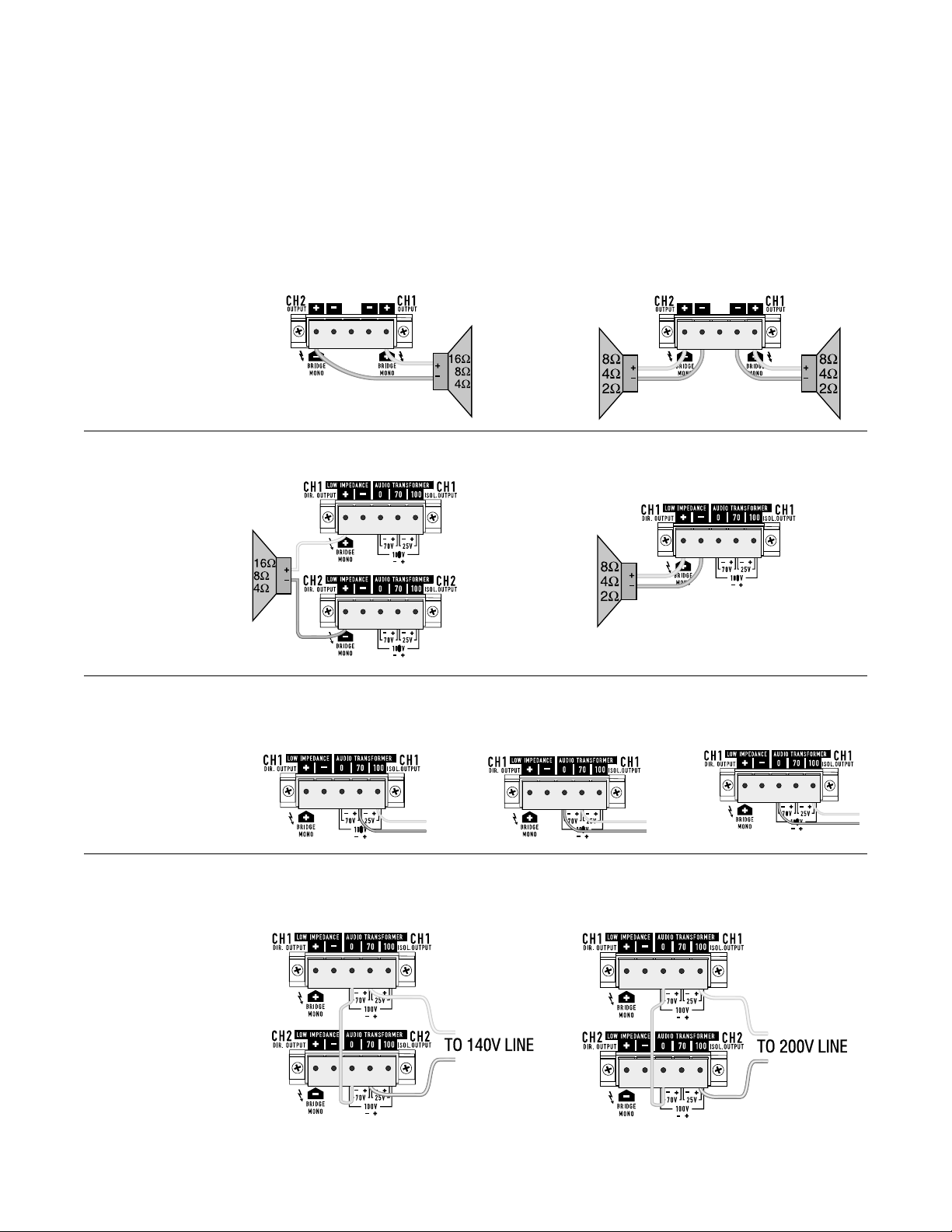
Output connections for CXT, bridged
mono mode, 200 volt line.
Output connections for CXT,
bridged mono mode, 140 volt
line.
If your application calls for connecting an 8-ohm speaker and a distributed line to the same amplifier channel,
the CX4T, CX6T and CX12T can do that. However, since most of the audio power is drawn by the direct-connected
speaker, you must derate the distributed line; the distributed line should have a total power load of no more than
one-fourth the amplifier’s normal distributed line power rating. Make sure the direct-connected speaker can
handle the 8-ohm power rating of the amplifier. See Applications Notes section for more details.
Output connections for CXT,
25 volt line.
Output connections for
CXT, 100 volt line.
Output connections for
CXT, 70 volt line.
Output connections for CXT, direct low
impedance
Output connections for CXT, bridged mono mode.
Output connections for CX, parallel or stereo mode.Output connections for CX, bridged mono mode.
8
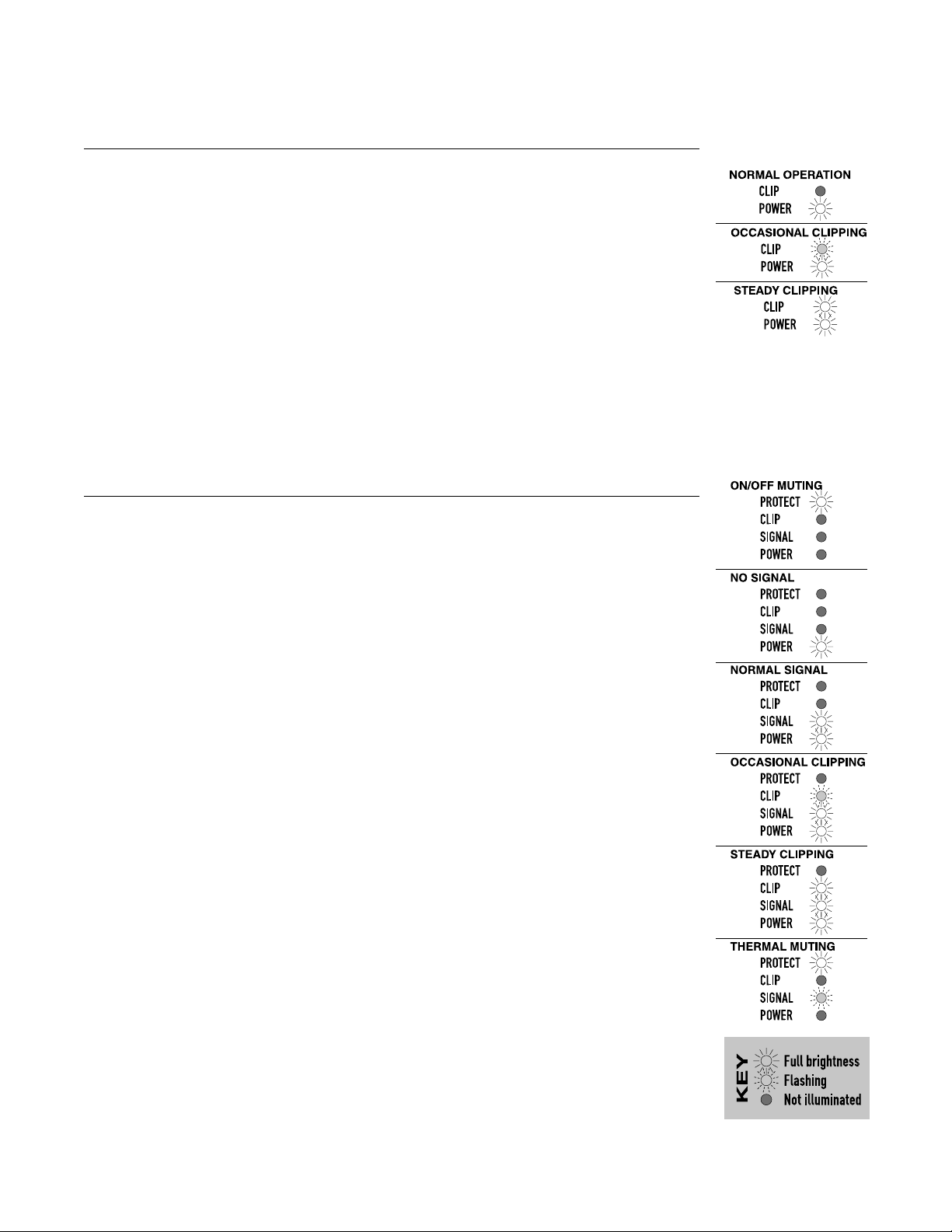
V . Controls & Displays
CX4 AND CX4T
The channel attenuator controls, labeled in dB of attenuation , are located on the rear panel. They have 11
detents, adjustable from 0 dB (full gain) to × (full attenuation). The LED displays for each channel function
as shown at right.
CX6, CX6T, CX12, AND CX12T
The channel attenuator controls, labeled in dB of attenuation , are located on the rear panel. They have 11
detents, adjustable from 0 dB (full gain) to × (full attenuation). The LED displays for each channel function
as shown at right.
VI. Operation
AC POWER
The amplifier is available for 100, 120, or 220-240 VAC, 50 or 60 Hz operation. Unless it is specially ordered
otherwise, each amplifier is configured for the line voltage in the market it is sold in. For example, those sold
in Japan are 100 VAC; for North and Central America, 120 VAC; for Europe and most of Asia, 220-240 VAC.
The power cord has a plug for connecting to a standard AC source. For 120-volt operation, the plug is a standard
15-ampere grounded NEMA fitting; it meets safety agency requirements for current consumption of less than
12 amperes during “normal” operation, but peak current draw under heavy usage can be higher.
Models built for 220 to 240-volt use have a standard Schuko (continental Europe) connector on the power cable.
OPERATION
CX4 and CX4T
When first powering up, start with the gain controls off until proper operation is verified (upon turning on
the AC switch, the “POWER” LED should come on, and after three seconds, the muting will stop and sound
can be heard). The amp should now be working.
Gain should be kept in the upper half of its range for full performance. “POWER” LED indicators are provided
to monitor the operation of each channel. Each channel has a red “CLIP” indicator that will show any
distortion in the amplifier. The mute circuit should cut the sound off as soon as you turn off the amp, and
mute for three seconds before restoring power to the speakers. This blocks turn-on and turn-off thumps.
LED Display for CX4 and
CX4T:
LED Display for CX6, CX6T,
CX12, and CX12T:

9
CX6, CX6T, CX12 and CX12T
When the amplifier is first turned on, the red “PROTECT” LED on each channel will light for about two or
three seconds, during which the output relays will stay open to mute the speakers. After the turn-on muting
interval, the “PROTECT” LEDs turn off, the green “POWER” LEDs light, and the output relays close to enable
the speaker outputs. Even during the muting interval, the yellow “SIGNAL” and red “CLIP” LEDs operate
normally if there is a signal present. If the “CLIP” LED is on while the amplifier is muted, cut the gain back
immediately to avoid a full-power blast of sound when the output relays close. If a channel stays muted
with “PROTECT” lit, or if its “SIGNAL” or “CLIP” indicators light up when the gain is turned all the way down,
it may be defective; see the troubleshooting segment for more information.
The “SIGNAL” LED indicates signal levels that are -30 dB (referenced to full rated output power) or higher.
Whe the amplifier is shut off, the amplifier should mute both channels virtually instantaneously, with the
“PROTECT” indicators lit until the power supplies are discharged.
TROUBLESHOOTING
Problem: Channel will not come out of muting
• If reducing the gain control to × attenuation does not release muting, the channel is defective or
overheated (see “Overheating,” below).
• If reducing the gain releases the muting, raise the gain back up slowly while you watch the “SIGNAL”
and “CLIP” indicators; the problem may be an abnormal signal (with excessive ultrasonic energy, for
example) that could otherwise damage your speakers.
PROBLEM: No sound (CX6/CX12)
• Is the channel muted? (If the “PROTECT” indicator is lit, the channel is muted; see below.)
• Is the “SIGNAL” LED lit or flashing? (If so, the speaker is open or blown, there is an open circuit in the
speaker wiring, or there is an open circuit in the internal output wiring of the amplifier.)
• If the “SIGNAL” indicator is dark, there is probably not enough signal, or even none at all. Try turning
up the rear panel attenuators or boosting the signal level at the input.
• If the “SIGNAL” indicator shows little or no activity but the “CLIP” LED is lit or flashing, there is probably
a short circuit in the speaker wiring, especially if the “PROTECT” indicator starts flashing. It is also
possible, but less likely, that the channel’s output relay is defective and will not open, thereby short-
circuiting the channel output and producing the same symptoms.
PROBLEM: Channel goes into muting, with “PROTECT” LED on (CX6/CX12)
• If the fan is running full speed, the channel probably suffers from severe overheating. Unless there
is a blockage in the flow of cooling air, the channel should return to normal within a minute or so (see
“Overheating,” below).
 Loading...