


PLX Series Professional Audio Amplifiers
User Manual
4-ohm minimum impedance models with Speakon® output terminals:
PLX 1104
PLX 1804
2-ohm minimum impedance models with Speakon and binding post terminals:
PLX 1802
PLX 2502
PLX 3102
PLX 3602
*TD-000214-00*
EN
ES
FR
DE
CH
TD-000214-00 Rev.E

Important Safety Precautions & Explanation of Symbols
1- Read these instructions.
2- Keep these instructions.
3- Heed all warnings.
4- Follow all instructions.
5- WARNING: To prevent fire or electric shock, do not expose this equipment to rain or moisture. Do not use this apparatus near water.
6- Clean only with a dry cloth.
7- Do not block any ventilation openings.
8- Do not install near any heat sources such as radiators, heat registers, stoves, or other apparatus (including amplifiers) that produce heat.
9- Do not defeat the safety purpose of the polarized or grounding-type plug. A polarized plug has two blades with one wider than the other.
EN A grounding plug has two blades and a grounding prong. The wide blade or third prong are provided for your safety. If the provided plug does not fit your outlet, consult an electrician for the replacement of the obsolete outlet.
10Protect the power cord from being walked on or pinched, particularly plugs, convenience receptacles, and the point where they exit from the apparatus.
11Use only attachments/accessories specified by QSC Audio Products, LLC
12Use only with hardware, brackets, stands, and components sold with the apparatus or by QSC Audio Products, LLC 13Unplug the apparatus during lightning storms or when unused for long periods of time.
14Refer all servicing to qualified service personnel. Servicing is required when the apparatus has been damaged in any way, such as power supply cord or plug is damaged, liquid has been spilled or objects have fallen into the apparatus, the apparatus has been exposed to rain or moisture, does not operate normally, or has been dropped.
The exclamation point within an equilateral triangle is intended to alert the user to the presence of important operating and maintenance (servicing) instructions in this manual.
The lightning flashes printed next to the OUTPUT terminals of the amplifier are intended to alert the user to the risk of hazardous energy. Output connectors that could pose a risk are marked with the lightning flash. Do not touch output terminals while amplifier power is on. Make all connections with amplifier turned off.
The lightning flash with arrowhead symbol within an equilateral triangle is intended to alert the user to the presence of uninsulated "dangerous" voltage within the product's enclosure that may be of sufficient magnitude to constitute a risk of electric shock to humans.
CAUTION: TO REDUCE THE RISK OF ELECTRIC SHOCK, DO NOT REMOVE THE COVER. NO USER-SERVICEABLE PARTS INSIDE. REFER SERVICING TO QUALIFIED PERSONNEL.
WARNING: To prevent fire or electric shock, do not expose this equipment to rain or moisture.
FCC INTERFERENCE STATEMENT
NOTE: This equipment has been tested and found to comply with the limits for a class B digital device, pursuant to part 15 of the FCC rules. These limits are designed to provide reasonable protection against harmful interference in a residential installation. This equipment generates, uses, and can radiate radio frequency energy and if not installed and used in accordance to the instructions, may cause harmful interference to radio communications. However, there is no guarantee that interference will not occur in a particular installation. If this equipment does cause harmful interference to radio or television reception, which can be determined by switching the equipment off and on, the user is encouraged to try to correct the interference by one or more of the following measures:
•Reorient or relocate the receiving antenna.
•Increase the separation between the equipment and the receiver.
•Connect the equipment into an outlet on a circuit different from that to which the receiver is connected. •Consult the dealer or an experienced radio or TV technician for help.
© Copyright 2006, QSC Audio Products, LLC
QSC® is a registered trademark of QSC Audio Products, LLC
"QSC" and the QSC logo are registered with the U.S. Patent and Trademark Office
Speakon® is a registered trademark of Neutrik Inc. All trademarks are the property of their respective owners.
2
Introduction
Thank you for purchasing this QSC power amplifier. Please read the following directions to obtain the best results. This manual covers all models of the PLX series. Illustrations show the PLX 1804 to be representative of the PLX 1104 and 1804 models, while the PLX 3602 illustration is representative of the PLX 1802, PLX 2502, PLX 3102, and PLX 3602 models.
The PLX 1104 and PLX 1804 models feature: •4-ohm minimum impedance
•Speakon loudspeaker connections
•QSC PowerLight high-performance, compact, and light weight switching power supply •Complete amplifier protection
•XLR and 1/4-inch TRS balanced input connectors
•Gain controls are recessed and 21-step detented
•Active inrush current limiting eliminates need for power sequencing
•LED indicators for power, input signal presence, -10 dB, and clip/protect
•Rear chassis tabs and front panel design protect controls and connectors
In addition, the PLX 1802, PLX 2502, PLX 3102, and PLX 3602 models feature:
•2-ohm minimum impedance •Bridgeable output
•Binding post loudspeaker connections •Clip limiter
•33 Hz low frequency filter
•Low-cut/full-range/high-cut selector •Stereo/bridge mode/parallel input selector
•Front panel LED indicators for parallel and bridge modes
EN
Unpacking
Factory packed carton contains: •PLX amplifier
•User's manual
•Adhesive rubber feet (for non-rack mount applications) •IEC-type detachable power cord
Use the same type carton when shipping the amplifier.
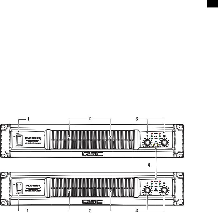
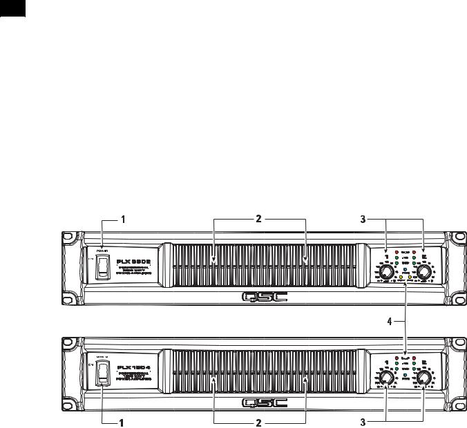
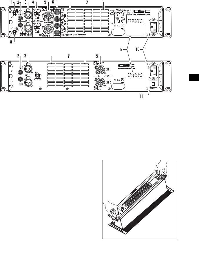
Front Panel
|
|
|
|
|
|
|
|
|
|
|
|
|
|
|
|
|
|
|
|
|
|
|
|
|
|
|
|
|
|
|
|
|
|
|
|
|
1- Power Switch |
3- LED Indicators |
|
|
|
|
|
|
|
|||
|
|
|
|
|||
|
|
2- Cooling Air Exhaust Vents |
4- Gain Controls |
3 |
||
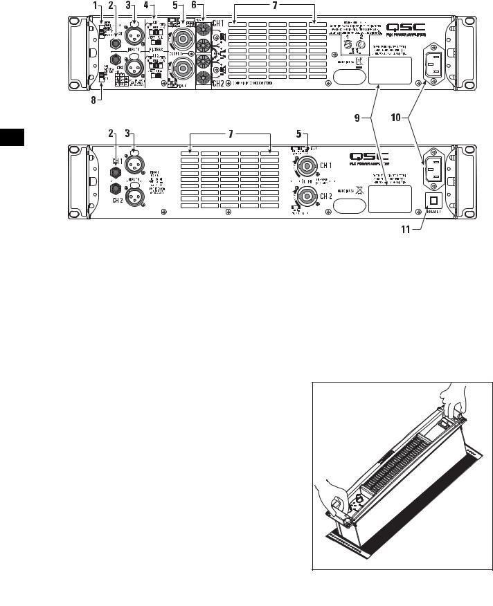
Rear Panel PLX 1802, PLX 2502, PLX 3102, PLX 3602
Rear Panel PLX 1104, PLX 1804
EN
|
|
|
|
|
|
|
|
|
|
|
|
|
|
|
|
|
|
|
|
|
|
|
|
|
|
|
|
|
|
|
|
|
|
|
|
|
|
|
|
|
|
|
|
|
|
|
|
|
|
|
|
|
|
|
|
|
|
|
|
|
|
|
|
|
|
|
|
|
|
|
|
|
|
|
|
|
|
|
|
|
|
|
|
|
|
|
|
|
|
|
|
|
|
|
|
|
|
|
|
|
|
|
|
|
|
|
|
|
|
|
|
|
|
|
|
|
|
|
|
|
|
|
|
|
|
|
|
|
|
|
|
|
|
|
|
|
|
|
|
|
|
|
|
|
|
|
|
|
|
|
|
|
|
|
|
|
|
|
|
|
|
|
|
|
|
|
|
|
|
|
|
|
|
|
|
|
|
|
|
|
|
|
|
|
|
|
|
|
|
|
|
|
|
|
|
|
|
|
|
|
|
|
|
|
|
|
|
|
|
|
|
|
|
|
|
|
|
|
|
|
|
|
|
|
|
|
|
|
|
|
|
|
|
|
|
|
|
|
|
|
|
|
|
|
|
|
|
|
|
|
|
|
|
|
|
|
|
|
|
|
1- Input Configuration switch |
|
|
|
7- Cooling air inlet vents |
|
|||||||||||||||||||||||||||||
|
|
|
|
|
|
|||||||||||||||||||||||||||||||
|
|
2- 1/4-inch TRS input connectors |
|
|
|
8- Clip Limiter switch |
|
|||||||||||||||||||||||||||||
|
|
3- XLR female input connectors |
|
|
|
9- Serial number plate |
|
|||||||||||||||||||||||||||||
|
|
4- Low Frequency Filter switches |
|
|
|
10- IEC-type AC mains inlet |
|
|||||||||||||||||||||||||||||
|
|
5- Speakon output connectors |
|
|
|
11Circuit breaker, resettable |
|
|||||||||||||||||||||||||||||
|
|
6- Binding post output connectors |
|
|
|
|
|
|
|
|
|
|
||||||||||||||||||||||||
Rack Mounting
Use four screws and washers to mount the amplifier to the equipment rack rails. To use the amplifier outside a rack, attach the self-adhesive rubber feet to the bottom.
For portable, mobile, or other applications where the rack assembly may be moved, we strongly recommend supporting the rear of the amplifier. A rear rack ear kit is available from QSC’s Technical Services Group.
The cast front panel includes finger grips at each end, making lifting and setting into the rack more comfortable.
The front panel casting includes features for finger-lifting and gripping at each end.
4
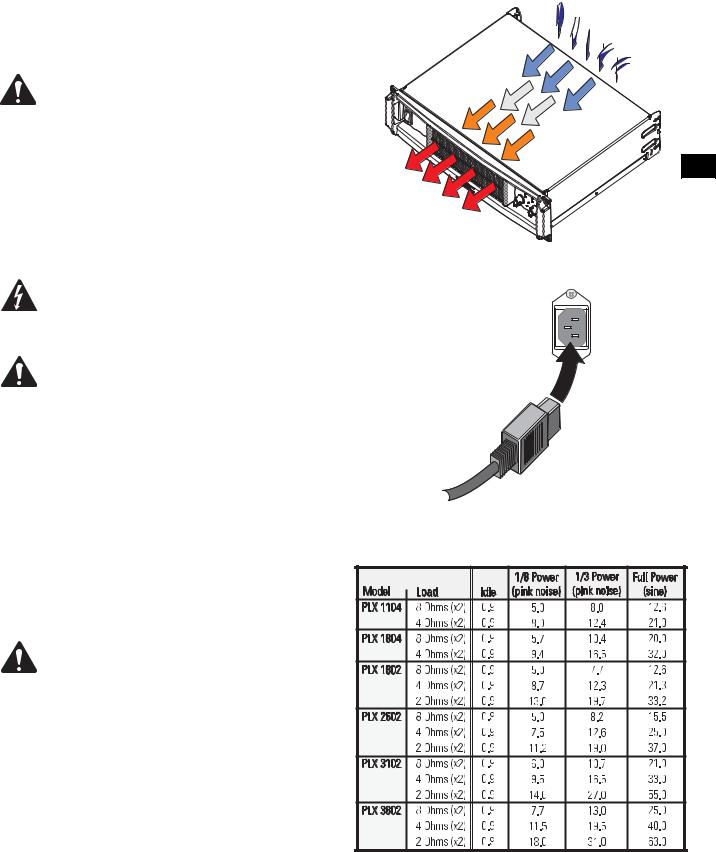
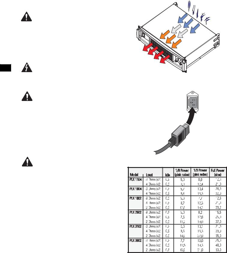
Cooling
Air flows from the rack, into the back of the amplifier, and out the front. This keeps the rack cool. The fan automatically runs faster when the amp is working hard.
Do not block the front or rear air vents!
Air flow in QSC amplifiers: Cool air is drawn into the rear of the amplifier by the cooling fan. Warm air exits the front of the amplifier.
AC Mains Connection
Connect AC power to the IEC socket on the back of the amplifier.
NOTE: Turn off the AC power switch before connecting AC power.
Connect the AC mains plug to a suitable AC mains outlet.
The correct AC line voltage is shown on the serial number label, on the rear panel. Connecting to the wrong line voltage may damage the amplifier or increase the risk of electric shock.
The rear chassis ear can be used to retain the IEC power connector. After inserting the IEC block into the receptacle, use a wire-tie or similar device to secure the cord to the chassis ear.
EN
Orient the IEC connector with the connector prongs in the socket, then push the connector firmly into the IEC socket until fully seated.
AC Mains Current Draw
The table at the right provides typical current draw for each model as a function of load and output power level. Units of measurement are amperes rms.
NOTE! Current draw shown is for 120 VAC line. For 230 VAC models, multiply values shown by 0.5.
•1/8 power (pink noise) represents typical program with occasional clipping. Use this rating for most applications.
•1/3 power (pink noise) represents severe program with heavy clipping.
•Full power (sine) is continuous sine wave driven at 1% clipping.
•PLX 1802, PLX 2502, PLX 3102, and PLX 3602 models: Thermal or overcurrent cutback limits duration of full power 2 ohm operation. Long term, active limiting to 30A at 120V.
•PLX 1104 and PLX 1804 models: Long-term, circuit breaker limited to 15A at 120V.
5

Input Configuration Switch (PLX 1802/2502/3102/3602 models only)
Select the input configuration by sliding the switch to the position which corresponds with the desired input configuration.
•Bridgeupper position
•Stereomiddle position
•Parallellower position
Stereo Mode: Each channel remains independent, and each may be used for a different signal.
Parallel Mode: This setting connects both inputs together. One input signal feeds both channels. Do not connect different sources to each input. Each channel's Gain control and speaker connection remain independent. In Parallel Mode, Channel 1 and Channel 2’s inputs are internally
EN connected in parallel. Use only one input when operating in Parallel Mode. The remaining input connector can be used for daisy-chaining the signal to other amplifiers.
Bridge Mode: This setting combines both channels into a single channel with twice the output voltage. Use only Channel 1’s input and Gain control. In Bridge Mode, Channel 1 and Channel 2’s inputs are internally connected in parallel. Use only one input when operating in Bridge Mode.
The remaining input connector can be used for daisy-chaining the signal to other amplifiers.
Use only one input when operating in parallel or bridge mode.
Clip Limiters (PLX 1802/2502/3102/3602 models only)
The amplifier has a clip limiter with an on-off switch. The limiter only responds to actual clipping, and automatically compensates for load and voltage variations. Clip limiting is generally recommended, especially to protect high frequency drivers.
•Set the switch UP (ON position) to use Clip Limiting.
•Set the switch DOWN (OFF position) to disable the clip limiter.
Low Frequency Filters (PLX 1802/2502/3102/3602 models only)
Each channel has independent filter selection of Full Range (infrasonic filter only), 33 Hz low cut,
100 Hz low cut, or 100 Hz High Cut. This allows tailoring the amplifier performance to that of the loudspeakers, offering the best possible performance from the system. Proper filtering reduces distortion and prevents amplifier overload.
TOP / FULL / SUB Switch: Select the type of loudspeaker being driven by each channel.
•Set the switch to the left for driving “top” boxes; applies 100 Hz low cut
•Set the switch to the middle position for “full range” loudspeakers.
•Set the switch to the rightmost position for driving subwoofers.
33 Hz (low cut) / FULL Switch: Unless the loudspeaker has extended low frequency capability, we recommend setting the filter to the 33 Hz setting. The filter should only be set to FULL (turned off) for driving subwoofers. Check the loudspeaker’s specifications and use the 33 Hz filter if the loudspeaker’s low frequency capability does not extend below 33 Hz.
•Set to FULL when driving loudspeakers that have low frequency capability below 33 Hz or in studio monitoring applications.
•Set to 33 Hz for loudspeakers which are not rated for frequencies below 33 Hz.
Input Configuration selector switch
Clip Limiter ON/OFF switch
Low Frequency filter selection switches for each channel
Low Frequency filter selection table
6
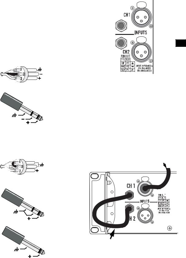
Inputs
Each channel has a balanced XLR (female) and 1/4-inch TRS input. The XLR and TRS connectors for each channel are wired in parallel and can be used for “daisy chaining” an input signal to additional amplifiers.
The input impedance is 20k ohm balanced or 10k ohm unbalanced. Both XLR and TRS inputs are connected with standard cables and can be changed quickly. Pinouts are marked on the rear panel. Do not attempt to connect more than one input signal to a given channel.
Balanced connections are recommended to reduce AC hum and interference, especially with long cable runs. Unbalanced connections may be suitable for short cables.
The signal's source impedance should be less than 600 ohms.
Input Pinouts
Balanced inputs: Connect to the plug as shown.
XLR
TRS
Unbalanced inputs: Connect to the plug as shown. If using an XLR connector, Pin 3 and pin 1 must be connected with a jumper as shown. If using a TRS connector, the ring and sleeve must be connected with a jumper. If a TS connector is used, the sleeve will provide the “jumper” when inserted into the input jack.
Input connectors and pinout chart (PLX1802 shown)
EN
PLX 1104 and PLX 1804 models can parallel the input signal to both channels by using a jumper from one channel to the next:
•Connect the input signal to either of Channel 1’s input connectors.
•Connect a jumper from Channel 1’s unused connector to either of Channel 2’s input connectors.
Input signal
XLR
TRS
TS |
TRS to TRS jumper from |
|
Channel 1 to Channel 2 |
7

Outputs
The PLX 1104 and PLX 1804 models are equipped with Speakon output connectors for each channel. PLX 1802, PLX 2502, PLX 3102, and PLX 3602 models are equipped with Speakon and binding post output connectors.
Wiring connections are shown on the back of the chassis. Carefully note the markings and maintain consistent loudspeaker polarity for optimum system performance.
Speakon Output Connectors
If making Speakon cables, be sure to connect the loudspeaker wiring as shown on the chassis. Channel 1’s Speakon provides 4-wire (Ch 1 + Ch 2)
EN connection; Channel 2’s Speakon provides 2-wire (Ch 2 only) connection. Appendix A provides Speakon connection reference.
Stereo and Parallel Mode: Connect each loudspeaker to its own channel of the amplifier, as shown on the chassis label. The INPUT CONFIGU-
RATION switch must be set for STEREO or PARALLEL mode.
Bridge Mode (PLX1802/2502/3102/3602 models only): Use Channel 1’s Speakon for Bridge mode output connection. Bridge mode configures the channel pair to drive a single high-power loudspeaker load. The INPUT CONFIGURATION switch must be set for BRIDGE mode. Use only Channel 1’s input and Gain control. Set Channel 2’s Gain control at minimum.
Binding Post Connectors (PLX 1802/2502/3102/3602
models only)
Stereo and Parallel Mode: Connect each loudspeaker to its own channel of the amplifier, as shown on the chassis label. The INPUT CONFIGURATION switch must be set for STEREO or PARALLEL mode.
Bridge Mode: Bridge mode configures the channel pair to drive a single high-power loudspeaker load. The INPUT CONFIGURATION switch must be set for BRIDGE mode. Use only Channel 1’s input and Gain control. Set Channel 2’s Gain control at minimum.
OUTPUT TERMINAL SAFETY WARNING! Do not touch output terminals while amplifier power is on. Make all connections with amplifier turned off. Risk of hazardous energy!
PLX 1104 and PLX 1804 Output Connectors: Do not use less than 4 ohm impedance loads with PLX 1104 and PLX 1804 models.
PLX 1802, PLX 2502, PLX 3102, and PLX 3602 Output Connectors: Do not use less than 2 ohm impedance loads with these models.
8
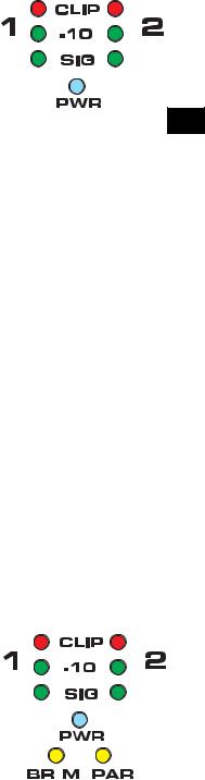
LED Indicators
The LED indicators can be used to monitor system operation and identify common problems.
POWER (PWR): BLUE
Normal indication:
•AC switch ON: LED will illuminate; on some models, LED will illuminate dimly during startup sequence.
If no indication:
•Check AC power cord and AC outlet.
•Confirm that AC switch is in ON position.
CLIP: RED
Normal indication:
•Illuminates whenever the amplifier is driven beyond full power. The resulting distortion corresponds to the brightness of the LED. Distortion that causes only brief flashing may not be audible.
•During muting, the red LED fully illuminates. This occurs during normal "On-Off" muting.
Abnormal indication:
•Bright red illumination while the amp is being used indicates either thermal muting or a shorted output.
•If the amplifier overheats, the fan will run at full speed, and operation should resume within one minute. Allow the fan to run, and make sure the amplifier ventilation is adequate.
•A shorted or overloaded output circuit will cause excessive Clip flashing and possible overheating.
•If distortion is audible without a Clip indication, the problem is either before or after the amplifier. Check for damaged speakers or overloaded signal source. The amplifier Gain control should be in the upper half of its range to prevent input overload.
SIGNAL (SIG), -10: GREEN
Normal indication:
•The SIG (signal) indicator illuminates when the output signal exceeds -35 dB, and the -10 (-10 dB) indicator illuminates when the signal exceeds -10 dB.
If no indication:
•Check Gain settings and increase gain if necessary. Check input connections and audio source for signal. If the Clip LED illuminates with little or no Signal indication, check the output wiring for shorts.
Abnormal indication:
•If the SIG or -10 LED illuminates with no signal input, there may be system oscillations or some other malfunction. Disconnect the load and fully reduce the gain. If the LED remains on, the amp may need servicing.
BRIDGE MONO (BR M) and PARALLEL (PAR) (PLX 1802/2502/3102/3602 models only):
•Each channel pair has a AMBER LED for Bridge Mode, and a AMBER LED for Parallel mode. These show how the rear panel INPUT CONFIGURATION switch is set (see Input Configuration
Switch). In Stereo mode, both LEDs should be OFF. In bridge mode the BR M and PAR indicator will be illuminated. In parallel mode, the PAR indicator will be illuminated.
LED indicators on PLX 1104 and PLX
1804 models
EN
LED indicators on PLX 1802, PLX 2502, PLX 3102, and PLX 3602 models
9
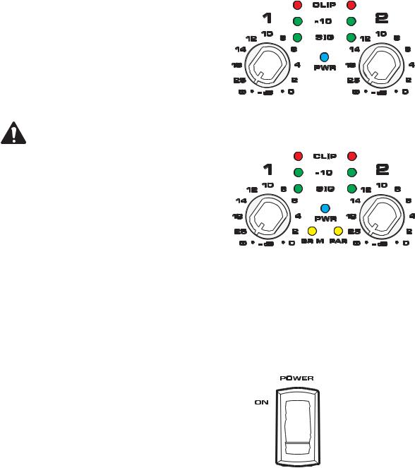
Gain Controls
Turn the GAIN controls clockwise to increase gain and counter clockwise to decrease gain.
|
The GAIN controls are marked in dB of attenuation. |
|
There are 21 detents for repeatable adjustments. The |
|
upper 14 steps are about 1 dB each, and settings should |
|
normally be made within this range. The range below - |
|
14 dB should not be used for normal program levels, as |
|
the input headroom could be exceeded, but can be used |
|
for testing at reduced levels. At the minimum setting, |
EN |
the signal is completely cut off. |
|
Note! The GAIN controls do not adjust the |
|
power of the amplifier. They adjust its sensi- |
|
tivity to input signals. |
Power Switch
Push in on the top of the rocker switch to apply AC mains power to the amplifier. Push in on the bottom of the rocker switch to turn the amplifier off.
When turned on, the blue PWR indicator LED and the red
CLIP indicator LED will illuminate; after a few seconds the red CLIP indicator will extinguish.
Gain controls and LED cluster on PLX 1104 and
PLX 1804 models
Gain controls and LED cluster on PLX 1802, PLX 2502, PLX 3102, and PLX 3603 models
10
Protection Systems
Both amplifier platforms are fully protected against adverse conditions, but their behavior and user adjustments are different.
PLX 1802/2502/3102/3602 models:
•Clip Limiting may be switched on the rear panel to prevent severe overdrive. This protects speakers and somewhat reduces the load on the amplifier.
•Internal current limits protect the output transistors against overloading. Peak limiting may occur at full output if using more than four 8-ohm speakers per channel, or if the speaker wiring is shorted. The red Clip LED will flash brightly, and the amplifier may sound distorted. If the amplifier is driven hard under these conditions, the current limit will be further reduced, causing an increase in distortion. If the amplifier appears to be losing power during peaks, check the speaker wiring and number of speakers. Using Clip Limiting will reduce this distortion, but for best results do not exceed the rated loading.
•If the amplifier stops completely for several seconds after a very loud signal, it may be overloading the AC service. This only occurs if the AC voltage sags more than 30%, and will be more likely if driving many speakers at once. Use short, heavygauge AC cables and do not plug too many amplifiers into a single outlet.
•In Bridge Mono, the amplifier may shut down for several seconds if driven too hard into loads less than the rated 4-ohm minimum.
•If the amplifier overheats due to prolonged overload or high external temperature, it will mute for about 30 seconds with the fan running at full speed for maximum cooling. Make sure the rear intake is getting a free flow of cool air.
EN
PLX 1104/1804 models:
•These models have completely automatic internal protection that maintains operation even under extreme conditions.
•Overdrive distortion will cause the red Clip LED to flash. If driven constantly into clipping, internal circuitry smoothly reduces the volume to minimize distortion and stress.
•These models are rated for 4-ohm loads. Do not use more than two 8-ohm speakers per channel. Using too many speakers may trigger limiting and cause a loss of volume.
•Internal current limits protect the output transistors against overloading. Moderate overloading will trigger clip limiting, and smoothly reduce output level to prevent distortion. Severe overloading, such as driving the amplifier hard into a shorted speaker wire, may cause short, rapid muting. Check the speaker wiring for shorts if the amplifier "chatters".
•Overheating may occur due to prolonged overdrive or high external temperature. This will first trigger thermal limiting, reducing volume so that the amplifier remains below its thermal limit and keeps running. If input signals are still too high, the amplifier may eventually mute for about 30 seconds with the fan at full speed for maximum cooling. Make sure the rear intake is getting a free flow of cool air.
11
Specifications PLX 1104, PLX 1804
|
|
|
PLX 1104 |
PLX 1804 |
|
OUTPUT POWER (Watts)(1) |
|
|
|
|
20 - 20k Hz, 0.05% THD, 8 ohms/Ch. |
|
310 |
550 |
|
1k Hz, 0.1% THD (EIA), 8 ohms/Ch. |
|
325 |
600 |
|
20 - 20k Hz, 0.05% THD, 4 ohms/Ch. |
|
500 |
800 |
|
1k Hz, 0.1% THD (EIA), 4 ohms/Ch. |
|
550 |
900 |
|
DISTORTION, SMPTE-IM |
|
0.02% |
0.02% |
|
FREQUENCY RESPONSE |
|
20 - 20k Hz, ±0.5 dB, all models |
|
|
SIGNAL to NOISE, unweighted, 20 - 20k Hz |
-108 dB |
-106 dB |
|
|
|
|
|
|
EN |
VOLTAGE GAIN |
|
32.5 dB |
34.9 dB |
|
INPUT SENSITIVITY, Vrms |
|
|
|
|
for rated power into 8 ohms |
|
1.18 (+3.7 dBu) |
1.20 (+3.8 dBu) |
|
OUTPUT CIRCUIT TYPE |
|
AB |
AB/H |
|
INPUT IMPEDANCE |
|
10k ohms unbalanced, 20k ohms balanced |
|
|
DYNAMIC HEADROOM |
|
2 dB at 4 ohms |
|
|
DAMPING FACTOR (8 ohms) |
|
>200 |
|
|
AMPLIFIER PROTECTION |
|
Short circuit, open circuit, thermal, ultrasonic and RF protection. Stable into reactive or mismatched loads |
|
|
COOLING |
|
Continuously variable speed fan; back-to-front air flow through heat sink array |
|
|
CONTROLS |
Front: |
AC POWER switch, Gain controls (each channel) 21 detents |
|
|
|
Back: |
AC circuit breaker |
|
|
LED INDICATORS |
|
POWER (blue), SIGNAL (green x 2), -10 dB (green x 2), CLIP (red x 2) |
|
|
CONNECTORS |
Input: |
1/4-inch TRS and female XLR; 20k ohm balanced, 10k ohm unbalanced |
|
|
|
Output: |
Speakon connectors: Ch 1, 4-wires (Ch 1 + Ch 2); Ch 2, 2-wires (Ch 2 only) |
|
|
LOAD PROTECTION |
|
Turn-on/turn-off muting, DC fault blocking, Clip limiting, Infrasonic filter (-3 dB at 5 Hz) |
|
|
POWER REQUIREMENTS |
|
Refer to rear panel serial number label. Configured at factory for 100, 120 or 220-240 VAC, 5060 Hz. |
|
|
DIMENSIONS |
|
19.0" (48.3 cm) W, 3.5" (8.9 cm) H, 10.1" (25.7 cm) D (from front mounting rails, including rear support |
|
|
|
|
ears) |
|
|
WEIGHT(1) |
|
13 pounds (5.9 kg) net; |
18 pounds (8.2 kg) shipping |
(1) NOTE: Due to special construction to meet EN-6100, CE models may have 5-12% (0.5 dBw) less power and 1.2 lb (0.6 kg) more weight.
U.S. patent no. 5767744 and patents pending
SPECIFICATIONS SUBJECT TO CHANGE WITHOUT NOTICE
12

Specifications PLX 1802, PLX 2502, PLX 3102, PLX 3602
|
PLX 1802 |
PLX 2502 |
PLX 3102 |
PLX 3602 |
OUTPUT POWER (Watts)(1) |
|
|
|
|
20 - 20k Hz, 0.05% THD, 8 ohms/Ch. |
320 |
425 |
550 |
725 |
1k Hz, 0.1% THD (EIA), 8 ohms/Ch. |
330 |
450 |
600 |
775 |
20 - 20k Hz, 0.05% THD, 4 ohms/Ch. |
525 |
675 |
900 |
1100 |
1k Hz, 0.1% THD (EIA), 4 ohms/Ch. |
575 |
750 |
1000 |
1250 |
1k Hz, 0.1% THD (EIA), 2 ohms/Ch. |
900 |
1250 |
1550 |
1800 |
Bridge Mono, 20 - 20k Hz, 0.1% THD, 8 ohms |
1100 |
1400 |
1900 |
2500 |
Bridge Mono, 1k Hz, 0.1% THD, 8 ohms |
1200 |
1500 |
2100 |
2600 |
Bridge Mono, 1k Hz, 1.0% THD, 4 ohms |
1800 |
2500 |
3100 |
3600 |
DISTORTION, SMPTE-IM |
<0.02%, all models |
|
|
|
FREQUENCY RESPONSE |
20 - 20k Hz, ±0.5 dB, all models |
|
|
|
SIGNAL to NOISE, unweighted, 20 - 20k Hz |
-107 dB |
-106 dB |
-107 dB |
-107 dB |
VOLTAGE GAIN |
31.9 dB |
34.0 dB |
35.0 dB |
35.9 dB |
INPUT SENSITIVITY, Vrms |
|
|
|
|
for rated power into 8 ohms |
1.28 (+4.4 dBu) |
1.15 (+3.4 dBu) |
1.23 (+4.0 dBu) |
1.25 (+4.2 dBu) |
EN
OUTPUT CIRCUIT TYPE |
|
AB |
AB/H |
AB/H |
AB/H |
INPUT IMPEDANCE |
|
10k ohms unbalanced, 20k ohms balanced |
|
|
|
DYNAMIC HEADROOM |
|
2 dB at 4 ohms |
|
|
|
DAMPING FACTOR (8 ohms) |
|
>500 |
|
|
|
AMPLIFIER PROTECTION |
|
Short circuit, open circuit, thermal, ultrasonic and RF protection. Stable into reactive or mismatched loads |
|||
COOLING |
|
Continuously variable speed fan; back-to-front air flow through heat sink array |
|||
CONTROLS |
Front: |
AC POWER switch, Gain controls (each channel) 21 detents |
|
||
|
Back: |
Input Configuration Switch (Stereo, Parallel, Bridge), Clip Limiters (On/Off) |
|
||
|
|
Subwoofer Switch (100 Hz Low Cut/Full Range/100 Hz High Cut, each channel) |
|||
|
|
LF Switch (33 Hz Low Cut/Full Range, 1 each channel) |
|
||
LED INDICATORS |
|
POWER (blue), SIGNAL (green x 2), -10 dB (green x 2), CLIP (red x 2), BRDG (amber), PAR (amber) |
|||
CONNECTORS |
Input: |
1/4-inch TRS and female XLR; 20k ohm balanced, 10k ohm unbalanced |
|
||
|
Output: |
Speakon connectors: Ch 1, 4-wires (Ch 1 + Ch 2); Ch 2, 2-wires (Ch 2 only) |
|
||
|
|
Binding posts |
|
|
|
LOAD PROTECTION |
|
Turn-on/turnoff muting, DC fault blocking, Clip limiting, infrasonic filter (-3 dB at 5 Hz). |
|||
POWER REQUIREMENTS |
|
Refer to rear panel serial number label. Configured at factory for 100, 120 or 220-240 VAC, 5060 Hz. |
|||
DIMENSIONS |
|
19.0" (48.3 cm) W, 3.5" (8.9 cm) H, 13.9" (35.3 cm) D (from front mounting rails, including rear support |
|||
|
|
ears) |
|
|
|
WEIGHT(1) |
|
21 pounds (9.5 kg) net; |
26 pounds (11.8 kg) shipping |
|
|
(1) NOTE: Due to special construction to meet EN-6100, CE models may have 5-12% (0.5 dBw) less power and 1.2 lb (0.6 kg) more weight.
U.S. patent no. 5767744 and patents pending
SPECIFICATIONS SUBJECT TO CHANGE WITHOUT NOTICE
13
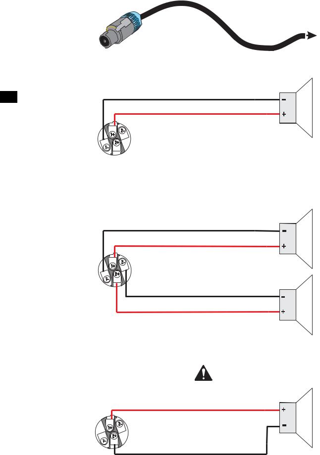
Appendix A: Speakon Wiring Reference
Amplifier connection |
To loudspeaker |
Two-wire, single-channel connection
EN
Four-wire, two-channel connection
NOTE! Ensure proper polarity when connecting bridge mode output!
Bridge mode connection
14

Precauciones importantes de seguridad y explicación de los símbolos
1- Lea estas instrucciones.
2- Conserve estas instrucciones.
3- Observe todas las advertencias.
4- Siga todas las instrucciones.
5- ADVERTENCIA: Para prevenir incendios o descargas eléctricas, no exponga este equipo a la lluvia ni a la humedad. No use este aparato cerca del agua.
6- Límpielo sólo con un paño seco.
7- No obstruya ninguna abertura de ventilación.
8- No lo instale cerca de fuentes de calor tales como radiadores, registros térmicos, estufas ni otros aparatos (inclusive amplificadores) que produzcan calor.
9- No anule ningún elemento de seguridad del enchufe polarizado o del enchufe con conexión a tierra. Un enchufe polarizado tiene dos hojas, una más ancha que la otra. Un enchufe con conexión a tierra tiene dos hojas y una patilla de conexión a tierra. La hoja ancha o el tercer terminal se proporcionan para su seguridad. Si el enchufe que se le proporciona no cabe en su tomacorriente, consulte con un electricista para reemplazar el tomacorriente obsoleto.
10Proteja el cable de alimentación para que no se camine sobre él ni se le comprima, particularmente los enchufes, los receptáculos y el punto en donde éstos salen del aparato.
11Use sólo piezas/accesorios especificados por QSC Audio Products, LLC ES
12Use sólo con herraje, soportes, estantes y componentes vendidos con el aparato o por QSC Audio Products, LLC
13Desenchufe el aparato durante tormentas eléctricas o cuando no lo vaya a usar durante periodos prolongados de tiempo.
14Refiera todo el servicio a personal calificado. Es necesario dar servicio al aparato cuando sufra algún daño, como cuando se daña el cable de alimentación eléctrica o el enchufe, cuando se derraman líquidos o caen objetos sobre el aparato, cuando éste ha estado expuesto a la lluvia o humedad, cuando no opere normalmente o cuando se haya caído.
El signo de exclamación dentro de un triángulo equilátero tiene la intención de alertar al usuario de la presencia de importantes instrucciones de operación y mantenimiento (servicio) en este manual.
Los rayos impresos cerca de los terminales de SALIDA del amplificador tienen la intención de alertar al usuario del riesgo de energía peligrosa. Los conectores de salida que pudiesen representar un riesgo están marcados con el símbolo del rayo. No toque los terminales de salida mientras el amplificador está encendido. Asegúrese de que todas las conexiones con el amplificador estén apagadas.
El símbolo del rayo con una punta de flecha dentro de un triángulo equilátero tiene la intención de alertar al usuario de la presencia de voltaje "peligroso" no aislado dentro de la caja del producto, que puede ser de magnitud suficiente para constituir un riesgo de descarga eléctrica a los seres humanos.
PRECAUCIÓN: PARA REDUCIR EL RIESGO DE DESCARGA ELÉCTRICA, NO QUITE LA CUBIERTA. EL INTERIOR NO CONTIENE PIEZAS A LAS QUE EL USUARIO PUEDA DAR SERVICIO. REFIERA EL SERVICIO A PERSONAL CALIFICADO.
ADVERTENCIA: Para prevenir incendios o descargas eléctricas, no exponga este equipo a la lluvia ni a la humedad.
DECLARACIÓN DE LA FCC RESPECTO A LA INTERFERENCIA
NOTA: Este equipo ha sido probado y se ha determinado que cumple con los límites de un dispositivo digital Clase B, en virtud de la parte 15 de las reglas de la FCC. Estos límites están diseñados para proporcionar protección razonable contra interferencia dañina en una instalación residencial. Este equipo genera, usa y puede irradiar energía de radiofrecuencia, y si no se instala y usa de acuerdo con las instrucciones, puede causar interferencia dañina a las comunicaciones de radio. Sin embargo, no hay garantía que no ocurrirá interferencia en una instalación en particular. Si este equipo causa interferencia dañina a la recepción de radio o televisión, lo cual se puede determinar al apagar y encender el equipo, se recomienda al usuario que trate de corregir la interferencia en una o más de las siguientes maneras:
•Reoriente o reubique la antena receptora.
•Aumente la separación entre el equipo y el receptor.
•Conecte el equipo en un tomacorriente de un circuito diferente al cual está conectado el receptor. •Consulte al distribuidor o a un técnico experimentado de radio o TV para solicitar ayuda.
© Copyright 2006, QSC Audio Products, LLC
QSC® es una marca comercial registrada de QSC Audio Products, LLC
“QSC” y el logotipo de QSC están registrados con la Oficina de Patentes y Marcas Comerciales de los Estados Unidos
Speakon® es una marca comercial registrada de Neutrik Inc. Todas las marcas comerciales son propiedad de sus respectivos propietarios.
15
Introducción
ES
Muchas gracias por la compra de este amplificador de potencia QSC. Por favor lea las siguientes instrucciones para obtener los mejores resultados. Este manual cubre todos los modelos de la serie PLX. Las ilustraciones muestran al modelo PLX 1804 como representativo de los modelos PLX 1104 y 1804, mientras que la ilustración del modelo PLX 3602 es representativo de los modelos PLX 1802, PLX 2502, PLX 3102 y PLX 3602.
Los modelos PLX 1104 y PLX 1804 incluyen:
•Impedancia de 4 ohmios como mínimo •Conexiones para altavoces Speakon
•Suministro de potencia de conmutación QSC PowerLight de alto rendimiento, compacto y ligero
•Completa protección del amplificador
•Conectores de entrada balanceada XLR y TRS de 1/4 de pulgada
•Los controles de ganancia están empotrados y tienen retenes de 21 pasos
•La limitación activa de la corriente de entrada elimina la necesidad de secuenciación de la potencia •Indicadores LED de potencia, presencia de señal de entrada, -10dB y recorte/protección
•Las aletas posteriores del chasis y el diseño del panel frontal protegen los controles y conectores
Además, los modelos PLX 1802, PLX 2502, PLX 3102 y PLX 3602 incluyen: •Impedancia de 2 ohmios como mínimo
•Salida con capacidad de puenteo
•Conexiones de altavoz mediante bornes de conexión •Limitador de recorte
•Filtro de frecuencia baja de 33 Hz
•Selector de corte bajo/intervalo completo/corte alto •Selector de estéreo/modo puente/entrada paralela
•Indicadores LED en el panel frontal para modos paralelo y puente
Desembalaje
La caja empacada en fábrica contiene:
•Amplificador PLX
•Manual del usuario
•Patas adhesivas de caucho (para aplicaciones de montaje que no sean en bastidor) •Cable de alimentación desprendible tipo IEC
Cuando embarque el amplificador utilice el mismo tipo de caja.
Panel frontal
|
|
|
|
|
|
|
|
|
|
|
|
|
|
|
|
|
|
|
|
|
|
|
|
|
|
|
|
|
|
|
|
|
|
|
|
|
|
|
|
|
|
|
|
|
|
|
|
|
|
|
|
|
|
|
|
|
1- Conmutador de encendido |
3- Indicadores LED |
|
||||
16 |
2- Aberturas de descarga del aire de enfriamiento |
4- Controles de ganancia |
|
||||
Panel posterior PLX 1802, PLX 2502, PLX 3102, PLX 3602
Panel posterior PLX 1104, PLX 1804
ES
1- Conmutador de configuración de entrada
2- Conectores de entrada TRS de 1/4 de pulgada
3- Conectores de entrada hembra XLR
4- Conmutadores del filtro de frecuencia baja
5- Conectores de salida Speakon
6- Conectores de salida del borne de conexión
Montaje en bastidor
Use cuatro tornillos y arandelas para montar el amplificador en los rieles del bastidor del equipo. Para usar el amplificador sin bastidor, instale las patas de caucho autoadhesivas en la parte inferior.
Para aplicaciones portátiles, móviles u otras aplicaciones donde puede moverse el conjunto del bastidor, recomendamos enfáticamente sujetar la parte posterior del amplificador. Se dispone de un juego de orejas de montaje posterior en bastidor del Grupo de Servicios Técnicos de
QSC.
El panel frontal fundido incluye sujetadores dactilares en cada extremo, que permiten levantar y colocar el equipo en el bastidor con mayor comodidad.
7- Aberturas de entrada del aire de enfriamiento
8- Conmutador limitador de recorte
9- Placa con el número de serie
10Entrada principal de CA tipo IEC
11Disyuntor, reajustable
La estructura fundida del panel frontal incluye dispositivos en cada extremo que permiten sujetar y levantar el equipo con los dedos.
17
Enfriamiento
El aire fluye desde el bastidor hacia el interior por la parte posterior del amplificador y hasta afuera por la parte frontal. Esto mantiene el bastidor frío. El ventilador automáticamente funciona más rápido cuando el amplificador está trabajando mucho.
¡No obstruya las aberturas de ventilación frontales o posteriores!
Flujo de aire en los amplificador QSC: El aire frío es arrastrado hacia el interior a través de la parte posterior del amplificador por el ventilador de enfriamiento. El aire caliente sale por el frente del amplificador.
Conexión a la línea principal de CA
Conecte la CA en el receptáculo IEC que se encuentra en la parte posterior del amplificador. NOTA: Apague el conmutador de CA antes de conectar la CA. Conecte el enchufe de la línea principal de CA a un tomacorriente apropiado de la línea principal de CA.
El voltaje correcto de la línea de CA se muestra en la
ES etiqueta del número de serie que se encuentra en el panel posterior. Si se conecta un voltaje de línea incorrecto se puede dañar el amplificador o aumentar el riesgo de una descarga eléctrica.
La oreja del chasis posterior puede utilizarse para retener el conector eléctrico IEC. Después de insertar el bloque IEC en el receptáculo, utilice un amarrador para cables o dispositivo similar para fijar el cable eléctrico a la oreja del chasis.
Consumo de corriente de la línea principal de CA
La tabla que aparece a la derecha proporciona el consumo de corriente típica para cada modelo como una función de la carga y del nivel de potencia de salida. Las unidades de medida son amperios rms.
¡NOTA! El consumo de corriente mostrado es para una línea de 120 de VCA. Para modelos de 230 de VCA, multiplique los valores mostrados por 0.5.
•1/8 de potencia (ruido rosa) representa el programa típico con recorte ocasional. Use esta clasificación para la mayoría de las aplicaciones.
•1/3 de potencia (ruido rosa) representa un programa de sonido pesado con recorte excesivo.
•La potencia total (seno) es una onda senoidal continua excitada a un recorte del 1%.
•Modelos PLX 1802, PLX 2502, PLX 3102 y PLX 3602: La reducción térmica o de la sobrecorriente limita la duración de la operación de potencia total de 2 ohmios. Limitación activa a largo plazo de 30A a 120V.
•Modelos PLX 1104 y PLX 1804: Disyuntor de largo plazo limitado a 15A a 120V.
Oriente el conector IEC con las patillas del mismo dentro del receptáculo, y luego empuje el conector firmemente en el receptáculo IEC hasta que quede completamente asentado.
18

Conmutador de configuración de la entrada (sólo modelos PLX 1802/2502/3102/3602)
Seleccione la configuración de entrada deslizando el conmutador a la posición que corresponde a la configuración de entrada deseada.
•Puenteposición superior •Estéreoposición central •Paraleloposición inferior
Modo estéreo: Cada canal permanece independiente, y cada uno se puede usar para una señal diferente.
Modo paralelo: Este ajuste conecta entre sí ambas entradas. Una señal de entrada alimenta ambos canales. No conecte fuentes diferentes a cada entrada. El control de ganancia y la conexión del altavoz de cada canal permanecen independientes. En el modo paralelo, las entradas del canal 1 y del canal 2 se conectan internamente en paralelo. Utilice únicamente una entrada al operar en el modo paralelo. El conector de entrada restante puede utilizarse para hacer conexiones de cadena en margarita de la señal a otros amplificadores.
Modo puenteado: Este ajuste combina ambos canales en un solo canal con el doble de la potencia de salida. Utilice únicamente la entrada y el control de ganancia del canal 1. En el modo puenteado, las entradas del canal 1 y del canal 2 se conectan internamente en paralelo. Utilice únicamente una entrada al operar en el modo puenteado. El conector de entrada restante puede utilizarse para hacer conexiones de cadena en margarita de la señal a otros amplificadores. Utilice únicamente una entrada al operar en el modo paralelo o puenteado.
Utilice únicamente una entrada al operar en el modo paralelo o puenteado.
Conmutador selector de configuración de la entrada
Conmutador de encendido/apagado del limitador de recorte
ES
Conmutadores de selección del filtro de baja frecuencia para cada canal
Limitadores de recorte (sólo modelos PLX 1802/2502/3102/3602)
El amplificador tiene un limitador de recorte con un conmutador de encendido-apagado. El limitador sólo responde al recorte real, y compensa automáticamente las variaciones de carga y de voltaje. Generalmente se recomienda la limitación de recorte, especialmente para proteger excitadores de alta frecuencia.
•Ajuste el conmutador HACIA ARRIBA (posición de ENCENDIDO) para usar la limitación de recorte.
•Ajuste el conmutador HACIA ABAJO (posición de APAGADO) para desactivar el limitador de recorte.
Filtros de baja frecuencia (sólo modelos PLX 1802/2502/3102/3602)
Cada canal tiene una selección de filtro independiente de intervalo completo (sólo filtro infrasónico), corte bajo de 33 Hz, corte bajo de 100 Hz o corte alto de 100 Hz. Esto permite adaptar el rendimiento del amplificador a aquel de los altavoces, ofreciendo el mejor rendimiento posible desde el sistema. El filtrado correcto reduce la deformación e impide la sobrecarga del amplificador.
Conmutador SUPERIOR / COMPLETO / SUB: Seleccione el tipo de altavoz que se está excitando por cada canal.
•Ajuste el conmutador hacia la izquierda para excitar las cajas “superiores”; aplica un corte bajo de 100 Hz
•Ajuste el conmutador en la posición central para altavoces de “intervalo completo”. •Ajuste el conmutador en la posición del extremo derecho para excitar los subwoofers.
Conmutador 33 Hz (corte bajo) / COMPLETO: A menos que el altavoz tenga una
capacidad de baja frecuencia extendida, recomendamos ajustar el filtro en el valor de 33 Hz. El filtro no debe ajustarse en COMPLETO (apagado) para excitar los subwoofers. Verifique las especificaciones del altavoz y utilice el filtro de 33 Hz si la capacidad de baja frecuencia del altavoz no se extiende por debajo de 33 Hz.
•Ajuste en COMPLETO al excitar altavoces que tengan una capacidad de frecuencia baja por debajo de 33 Hz o en aplicaciones de supervisión de estudio.
•Ajuste en 33 Hz para altavoces que no están clasificados para frecuencias por debajo de 33 Hz.
Tabla de selección de filtros de baja frecuencia
19

Entradas
Cada canal tiene una entrada balanceada XLR (hembra) y TRS de 1/4 de pulgada. Los conectores XLR y TRS para cada canal se cablean en paralelo y pueden usarse para conectar en “cadena en margarita” una señal de entrada a amplificadores adicionales.
La impedancia balanceada de entrada es de 20 k ohmios o no balanceada de 10 k ohmios. Las entradas XLR y TRS están conectadas con cables estándar y se pueden cambiar rápidamente. Los conjuntos de patas están marcados en el panel posterior.
No trate de conectar más de una señal de entrada a un canal dado.
Se recomiendan conexiones balanceadas para reducir el zumbido y la interferencia de la CA, especialmente en tramos largos de cable. Las conexiones no balanceadas pueden ser adecuadas para tramos cortos de cable. La impedancia de la fuente de la señal debe ser menor de 600 ohmios.
Conjuntos de patas de entrada
Entradas balanceadas: Conecte al enchufe como se muestra.
ES
XLR
TRS
Entradas no balanceadas: Conecte al enchufe como se muestra. Si está usando un conector XLR, la pata 3 y la pata 1 deben estar conectadas con un puente, tal como se muestra. Si está usando un conector TRS, el anillo y el manguito deben estar conectados con un puente. Si se usa un conector TS, el manguito proporcionará el “puente” al insertarlo en el receptáculo de entrada.
Cuadro de conectores de entrada y conjunto de patillas (se muestra el modelo PLX1802)
Los modelos PLX 1104 y PLX 1804 pueden emitir en paralelo la señal de entrada a ambos canales usando un puente de un canal al siguiente:
•Conecte la señal de entrada a cualquiera de los conectores de entrada del canal 1.
•Conecte un puente desde el conector no utilizado del canal 1 a cualquiera de los conectores de entrada del canal 2.
Señal de entrada
XLR
TRS
TS |
Puente TRS a TRS del canal |
|
1 al canal 2 |
20
Salidas
Los modelos PLX 1104 y PLX 1804 están equipados con conectores de salida Speakon para cada canal. Los modelos PLX 1802, PLX 2502, PLX 3102 y PLX 3602 están equipados con conectores de salida Speakon y de borne de conexión.
Las conexiones del cableado se muestran en la parte posterior del chasis.
Observe atentamente las marcas y mantenga una polaridad constante del altavoz para lograr un óptimo rendimiento del sistema.
Conectores de salida Speakon
Si está tendiendo cables para el conector Speakon, asegúrese de conectar el cableado del altavoz tal como se muestra en el chasis. El conector Speakon del canal 1 proporciona una conexión de 4 hilos (canal 1 + canal
2); el conector Speakon del canal 2 proporciona una conexión de 2 hilos
(sólo canal 2). El apéndice A proporciona una referencia de conexión a los conectores Speakon.
Modo estéreo y en paralelo: Conecte cada altavoz a su propio canal del amplificador, como se muestra en la etiqueta del chasis. El conmutador de CONFIGURACIÓN DE ENTRADA debe ajustarse para el modo ESTÉREO o EN PARALELO.
Modo puenteado (sólo modelos PLX1802/2502/3102/3602): Use el conector Speakon del canal 1 para la conexión de salida del modo puenteado. El modo puenteado configura el par de canales para que excite una sola carga de alta potencia del altavoz. El conmutador de CONFIGURACIÓN DE ENTRADA debe ajustarse para el modo
PUENTEADO. Utilice únicamente la entrada y el control de ganancia del canal 1. Ajuste el control de ganancia del canal 2 en su valor mínimo.
Conectores del borne de conexión (sólo modelos PLX 1802/2502/3102/3602)
Modo estéreo y en paralelo: Conecte cada altavoz a su propio canal del amplificador, como se muestra en la etiqueta del chasis.
El conmutador de CONFIGURACIÓN DE ENTRADA debe ajustarse para el modo ESTÉREO o EN PARALELO.
Modo puenteado: El modo puenteado configura el par de canales para que excite una sola carga de alta potencia del altavoz. El conmutador de CONFIGURACIÓN DE ENTRADA debe ajustarse para el modo PUENTEADO. Utilice únicamente la entrada y el control de ganancia del canal 1. Ajuste el control de ganancia del canal 2 en su valor mínimo.
¡ADVERTENCIA SOBRE LA SEGURIDAD DE LOS TERMINALES DE SALIDA! No toque los terminales de salida mientras el amplificador está
encendido. Asegúrese de que todas las conexiones con el amplificador estén apagadas. ¡Riesgo de energía peligrosa!
Conectores de salida en los modelos PLX 1104 y
PLX 1804: No use cargas de menos de 4 ohmios de impedancia con los modelos PLX 1104 y PLX 1804.
ES
Conectores de salida de los modelos PLX
1802, PLX 2502, PLX 3102 y PLX 3602: No use cargas de menos de 2 ohmios de impedancia con estos modelos.
21
 Loading...