


Powerlight 9.0PFC
HEAR THE POWER OF TECHNOLOGY.
PowerLight™ Series
Two-Channel Power Amplifiers
TECHNICAL SERVICE MANUAL
▲▲
▲ PowerLight 6.0 II
▲▲
▲▲
▲ PowerLight 6.0
▲▲
▲▲
▲ PowerLight 9.0
▲▲
PFC
PFC
22 22
1 -CHANNEL- 2
24 24
ON
OFF
PROTECT
STANDBY
POWER
1 CHANNEL 2
POWERLIGHT 9.0
PFC
9000 WATT POWER FACTOR CORRECTED PROFESSIONAL AMPLIFIER
20 20
18 18
14 14
88
-00 -00
CLIP
26 26
-10dB
28 28
-20dB
30 30
SIGNAL
32 32
CLIP LIMITER
dB
dB
*TD-000083-00*
TD-000083-00
Rev. Prelim.


PowerLight Series
Technical Service Manual
▲▲
▲ PowerLight 6.0 II
▲▲
▲▲
▲ PowerLight 6.0
▲▲
▲▲
▲ PowerLight 9.0
▲▲
IMPORTANT NOTICE:
This document contains proprietary information that is the property
of QSC Audio Products, Inc, and may not be disclosed, reproduced or
used without express or written consent from QSC Audio Products.
QSC Audio Products, Inc.
Technical Services Group
Phone: 1-800 QSC AUDIO (1-800-772-2834) USA only
+1 (714) 957-7150
Fax: +1 (714) 754-6173
Postal: 1665 MacArthur Blvd.
Costa Mesa, California 92626 USA
E-mail: tech_support@qscaudio.com
Web: http://www.qscaudio.com (product information and support)
http://www.qscstore.com (parts and accessory sales)
PFC
PFC
Copyright 2004 QSC Audio Products, Inc. All rights reserved.
Document # TD-000083-00, Preliminary Rev. Released November 2004.
Technical Service Manual 1
PowerLight 6.0 II, PowerLight 6.0
PFC
, and PowerLight 9.0
PFC
PowerLight 9.0
PFC
PowerLight 6.0
PFC
PowerLight 9.0 II
2 QSC Audio Products, Inc.
TD-000083-00

Table of Contents
Performance Specifications ............................................................................................................................................................................................... 4
1. Introduction ..................................................................................................................................................................................................... 5
1.1 Service bulletins.............................................................................................................................................................................................................. 5
1.2 The well-equipped service bench ............................................................................................................................................................................... 5
1.3 Working with surface-mount components................................................................................................................................................................. 5
T wo-terminal components (resistors, capacitors, diodes, etc.)............................................................................................................................................................. 5
Multi-pin components (ICs, etc.) ........................................................................................................................................................................................................ 6
Three-terminal components (transistors, etc.) .................................................................................................................................................................................... 6
1.4 Series description ........................................................................................................................................................................................................... 6
1.5 Technical descriptions and theory of operation........................................................................................................................................................ 7
Power supplies ................................................................................................................................................................................................................................. 7
Audio circuitry................................................................................................................................................................................................................................... 7
2. Servicing the amplifier .................................................................................................................................................................................. 8
2.1 Mechanical disassembly and reassembly ................................................................................................................................................................. 8
Introduction...................................................................................................................................................................................................................................... 8
T ools and materials needed .............................................................................................................................................................................................................. 8
Disassembly ..................................................................................................................................................................................................................................... 8
Reassembly.................................................................................................................................................................................................................................... 11
2.2 The display board.......................................................................................................................................................................................................... 13
2.3 AC line filter ................................................................................................................................................................................................................... 13
2.4 Power supply servicing................................................................................................................................................................................................ 15
Bench testing power supply modules .............................................................................................................................................................................................. 15
Replacing switching MOSFET s in PFC models.................................................................................................................................................................................. 15
Suggestions for troubleshooting..................................................................................................................................................................................................... 17
Adjusting and calibrating the power supply module......................................................................................................................................................................... 18
2.5 AC voltage conversions................................................................................................................................................................................................ 22
2.6 Bias adjustments ........................................................................................................................................................................................................... 22
3. Troubleshooting ............................................................................................................................................................................................ 23
3.1 Initial check ................................................................................................................................................................................................................... 23
3.2 Preliminary troubleshooting........................................................................................................................................................................................ 23
3.3 Further troubleshooting ................................................................................................................................................................................................ 24
4. Parts ................................................................................................................................................................................................................. 25
4.1 Semiconductor package descriptions and pinouts ................................................................................................................................................ 25
4.2 Parts lists ........................................................................................................................................................................................................................ 33
Chassis Assembly (QSC part #WP-000268-00) ................................................................................................................................................................................ 33
Chassis Assembly (QSC part # WP-000268-02) ............................................................................................................................................................................... 34
Chassis Assembly (QSC part # WP-000260-00) ............................................................................................................................................................................... 35
Chassis Assembly (QSC part # WP-000260-02) ............................................................................................................................................................................... 36
Chassis Assembly (QSC part # WP-000170-00) ............................................................................................................................................................................... 37
Chassis Assembly (QSC part # WP-000170-02) ............................................................................................................................................................................... 38
Chassis Assembly, Rear (QSC part # WP-000271-00)....................................................................................................................................................................... 39
Chassis Assembly, Rear (QSC part # WP-000264-00)....................................................................................................................................................................... 39
Chassis Assembly, Rear (QSC Part # WP-000172-00)....................................................................................................................................................................... 40
Output PCB Assembly (QSC part # WP-000179-00) ......................................................................................................................................................................... 40
Input PCB Assembly (QSC part # WP-000272-00)............................................................................................................................................................................ 40
Input PCB Assembly (QSC part # WP-000265-00)............................................................................................................................................................................ 41
Input PCB Assembly (QSC part # WP-000175-00)............................................................................................................................................................................ 41
Input Daughterboard Assembly (QSC part # WP-000178-00)........................................................................................................................................................... 42
Audio Channel Module Assembly (QSC part number WP-000276-00)............................................................................................................................................. 42
Audio Channel Module Assembly (QSC part # WP-000182-00) ....................................................................................................................................................... 46
Power Supply Assembly (QSC part # WP-000266-00)...................................................................................................................................................................... 50
Power Supply Assembly (QSC part # WP-000266-02)...................................................................................................................................................................... 52
Power Supply Assembly (QSC part # WP-000262-00)...................................................................................................................................................................... 55
Power Supply Assembly (QSC part # WP-000262-02)...................................................................................................................................................................... 56
Power Supply Controller Assembly (QSC part # WP-000263-00)...................................................................................................................................................... 58
Power Supply Assembly (QSC part # WP-000173-00)...................................................................................................................................................................... 60
Power Supply Assembly (QSC part # WP-000180-00)...................................................................................................................................................................... 61
Power Supply Controller Assembly (QSC part # WP-000174-00)...................................................................................................................................................... 63
Display PCB Assembly (QSC part number WP-000176-00)............................................................................................................................................................... 64
Line Filter Assembly (QSC part number WP-000177-00)................................................................................................................................................................... 66
Line Filter Assembly (QSC part number WP-000181-00)................................................................................................................................................................... 66
Matched FET s................................................................................................................................................................................................................................. 67
5. Schematic diagrams .................................................................................................................................................................................... 68
Technical Service Manual 3
PowerLight 6.0 II, PowerLight 6.0
PFC
, and PowerLight 9.0
PFC

Performance Specifications
PowerLight 6.0 II PowerLight 6.0
PFC
PowerLight 9.0
PFC
OUTPUT POWER
in watts
FTC: 20 Hz–20 kHz, both channels driven
8Ω per channel 1150 (< 0.1% THD) 1400 (< 0.1% THD) 1800 (< 0.2% THD)
4Ω per channel 2050 (< 0.1% THD) 2500 (< 0.1% THD) 3200 (< 0.2% THD)
2Ω per channel 3250 (< 0.1% THD) 3250 (< 0.1% THD)
EIA: 1 kHz @ 1% THD, both channels driven
8Ω per channel 1300 1600 1950
4Ω per channel 2200 2800 3400
2Ω per channel 3500 3500 4500
Bridge Mono:
16Ω, 1 kHz, 1% THD 2600 3200 3900
8Ω, 1 kHz, 1% THD 4400 5600 6800
4Ω, 1 kHz, 1% THD 7000 7000 9000
DYNAMIC HEADROOM 0.77 dB @ 4Ω
DISTORTION
THD: 20 Hz–20 kHz (8, 4, & 2Ω @ 10 dB below rated power) < 0.06% < 0.15%
(8 & 4Ω @ FTC rated power) < 0.1% (20 Hz–20 kHz) < 0.02% (20 Hz–2 kHz) < 0.03% (20 Hz–2 kHz)
20 Hz–2 kHz (2Ω) < 0.1% (20 Hz–20 kHz @ 3250 W) < 0.02% (@ 3250 W) < 0.05% (@ 4500 W)
SMPTE-IM: < 0.02% < 0.02% < 0.02%
FREQUENCY RESPONSE 20 Hz–20 kHz, ±0.15 dB
(at 10 dB below rated output power) -3 dB points: 2 Hz and 50 kHz
DAMPING FACTOR > 2000 @ 8Ω, at 1 kHz and below
NOISE (unweighted 20 Hz to 20 kHz, below rated output) 107 dB 107 dB 107 dB
VOLTAGE GAIN 40× (32 dB)
INPUT SENSITIVITY, V RMS
full rated power @ 8Ω 2.4 v (+9.8 dBu) 2.6 v (+10.6 dBu) 3.0 v (+11.8 dBu)
full rated power @ 4Ω 2.3 v (+9.5 dBu) 2.5 v (+10.2 dBu) 3.8 v (+11.2 dBu)
INPUT IMPEDANCE 10 kΩ unbalanced
20 kΩ balanced
CONTROLS Front: AC switch, Ch. 1 and Ch. 2 gain, Ch. 1 and Ch. 2 clip limiter switches
Rear: Parallel/Stereo/Bridge switch, remote power supply enable terminals
INDICATORS each channel PROTECT: Red LED CLIP: Red LED
STANDBY: Yellow LED -10 dB: Yellow LED
POWER: Green LED -20 dB: Yellow LED
SIGNAL: Green LED
CONNECTORS Input: Active balanced; “Euro-style” terminal block; Neutrik “Combo” XLR
and ¼" (6.3 mm) TRS, tip and pin 2 positive
Output: “Touch-Proof” binding posts (60A rated) and Neutrik Speakon™ (1 per channel)
DataPort: HD 15 female connector for use with QSControl, Basis, or accessories
COOLING Four continuously variable speed fans, back-to-front air flow
AMPLIFIER PROTECTION Full short circuit, open circuit, thermal, ultrasonic, and RF protection
Stable into reactive or mismatched loads
LOAD PROTECTION Turn-on/turn-off muting,
OUTPUT CIRCUIT TYPE H: Full-bridge current cell vertical N-channel MOSFET linear output with Class H 4-step high efficiency circuit
DIMENSIONS 19.0" (48.3 cm) wide, 3.5" (8.9 cm) tall (2 rack spaces)
17.9" (45.5 cm) rack mounting to rear support ears; 19.5” (49.5 cm) overall
WEIGHT Shipping: 59 lb. (26.8 kg) 65 lb. (29.5 kg) 65 lb. (29.5 kg)
Net: 53 lb. (24.1 kg) 59 lb. (26.8 kg) 59 lb. (26.8 kg)
POWER REQUIREMENTS Available for 120 or 220–240 VAC, 50/60 Hz
POWER CONSUMPTION
(both channels driven)
Multiply currents by 0.5 for 230V units
@ 120 VAC
Typical
1
Full2Max
Idle
8Ω
2.5 A 10.3 A 19.3 A 39.3 A
4Ω
2.5 A 15.5 A 35.1 A 67.5 A
2Ω
2.5 A 23.8 A 47.4 A 104.7 A
1
Pink noise at 1/8 of full power; analogous to typical program with occasional clipping.
2
Pink noise at 1/3 of full power; analogous to typical program with heavy clipping.
3
Continuous sine wave at threshold of clipping (1% THD).
3
Idle
8Ω
2.5 A 10.3 A 19.3 A 39.3 A
4Ω
2.5 A 15.5 A 35.1 A 67.5 A
2Ω
2.5 A 23.8 A 47.4 A 104.7 A
Typical
1
Full2Max
3
Idle
8Ω
2.5 A 10.3A 19.3 A 39.3 A
4Ω
2.5 A 15.5A 35.1 A 67.5 A
2Ω
2.5 A 23.8A 47.4 A 104.7A
Typical
1
Full2Max
US patents pending
SPECIFICATIONS SUBJECT TO CHANGE WITHOUT NOTICE
3
4 QSC Audio Products, Inc.
TD-000083-00
1. Introduction
1.1 Service bulletins
Contact QSC Technical Services to make sure you have the most
up-to-date service bulletins for PowerLight Series amplifiers.
Service bulletins may be distributed in hard copy, via fax, and
electronically (Adobe Acrobat PDF) via CD-ROMs, FTP from the QSC
web site (www.qscaudio.com), and e-mail.
These service bulletins had been issued at the time this manual
was printed: PFC0001, “PFC MOSFET Replacement” (PowerLight
PFC
6.0
and PowerLight 9.0
Replacement Guidelines” (PowerLight 6.0
only); and PFC0003, “Amplifier Goes Into Protect When Turned On”
(all three models).
PFC
only); PFC0002, “PFC Power Supply
PFC
and PowerLight 9.0
PFC
1.2 The well-equipped service
bench
To properly service QSC amplifiers, a technician needs the right
tools. The technician’s service bench should have the following
equipment:
• Digital multimeter with RMS AC voltage and current
• Digital clamp-on ammeter
• Dual-trace oscilloscope
• Audio distortion analyzer
• Non-inductive load resistors, configurable as 8 ohms (min. 1800
watts capacity), as 4 ohms (min. 3200 watts capacity), and as
2 ohms (min. 4500 watts capacity)
• Variable AC voltage source, such as a Variac or Powerstat
variable transformer, with a rated current capacity of up to 50A
(for 120V models) or 25A (for 230V models)
• Low-distortion audio sine wave generator
• Philips and flat screwdrivers
• Soldering iron with a fine tip (25–60W recommended)
• Rosin-core solder (60/40 or 63/37)
• Long-nose pliers
• Diagonal cutters
• Wire strippers
Automated test equipment, such as an Audio Precision worksta-
tion, is very useful for servicing PowerLight amplifiers. Contact
QSC Technical Services to obtain applicable AP test files.
Servicing power supply modules will require some additional
special-built equipment:
• Power supply remote controller
• PFC power supply fixture (for PFC modules only)
• CMP box
Becauseof the complexity of the PFC power supplies, QSC
recommends they be serviced only by QSC.
1.3 Working with surface-mount
components
PowerLight amplifiers, like many modern electronic products, use
surface-mount technology (SMT) components where appropriate in
order to make high-density circuitry that is reliable and economical
to manufacture.
SMT components in the PowerLight amps are used in the smallsignal and control circuits, so they do not handle significant
amounts of power; therefore, they are subject to very little stress
and should seldom fail. Sometimes they do fail, or they require
replacement for a performance upgrade or modification. Thus, it is
important to know how to work with SMT components.
Specialized tools and equipment exist for soldering, unsoldering,
and removing SMT components quickly and efficiently, but they are
often expensive. Most SMT repairs, though, can be handled reasonably well with common tools and equipment, such as tweezers,
solder braid, and fine-tip soldering irons.
T wo-terminal components (resistors, capacitors,
diodes, etc.)
Removal
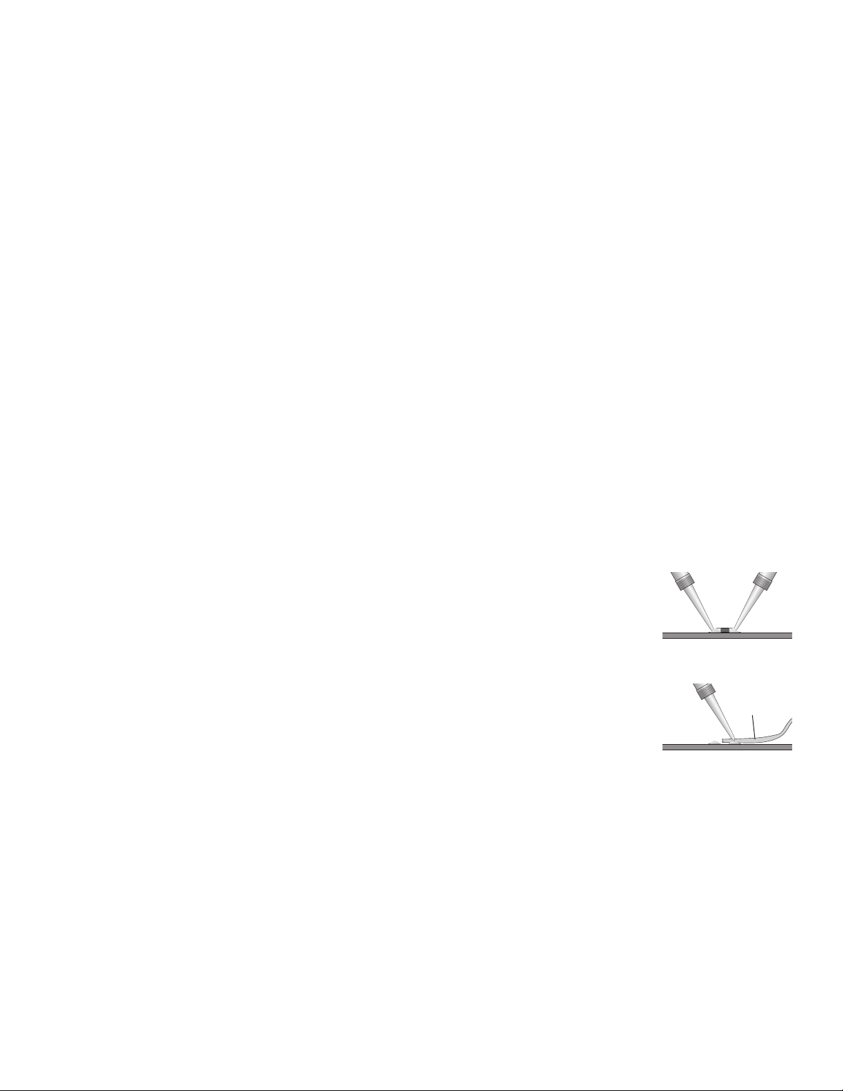
1. Use two soldering irons, prefer-
ably about 25 to 40 watts, with
fine tips.
2. With a soldering iron in each
hand, hold one tip on the solder at
one end of the component and the
other tip on the other end (Figure
1.1).
3. Once the solder melts on both
ends, grip the component
between the two tips and lift it
from the circuit board.
4. Use solder braid and a soldering
iron to remove the solder from the
two pads (Figure 1.2).
Insertion
1. With a soldering iron and 60/40 or 63/37 eutectic-type solder,
melt just enough solder onto one pad to create a small mound
(Figure 1.3).
2. Grasp the component in the middle with tweezers. Melt the
small mound of solder with the iron and place the component
across the two pads (in the correct orientation, if the component is sensitive to direction) and press it flat against the circuit
board, with one end of the component immersed in the melted
solder (Figure 1.4).
3. Hold the component in place and take the soldering iron away.
Figure 1.1.
Solder braid
Figure 1.2.
Technical Service Manual 5
PowerLight 6.0 II, PowerLight 6.0
PFC
, and PowerLight 9.0
PFC
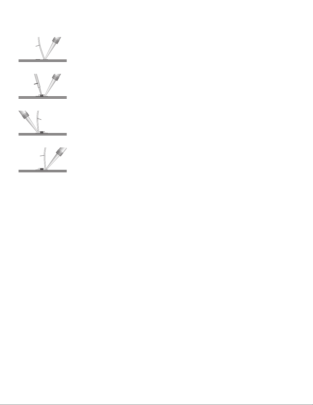
Solder
Figure 1.3.
Tweezers
Figure 1.4.
Figure 1.5.
Solder
Figure 1.6.
Solder
Let the solder harden to tack the
component in place.
4. Fully solder the other end of the
component to its pad. Let the
solder harden (Figure 1.5).
5. Fully solder the tacked end of
the component to its pad (Figure
1.6).
Three-terminal
components (transistors,
etc.)
Removal
1. With a soldering iron and solder
braid, remove as much solder as
possible from the middle
terminal of the component.
2. With a soldering iron in each
hand, hold one tip on the solder
at the terminal at one end of the
component and the other tip on
the terminal at the other end.
3. When the solder on both ends
2. With fine tweezers, carefully try to lift each pin to see if it’s
free. If it’s not, touch it with the tip of the soldering iron and if
necessary, use the solder braid to remove the remaining solder.
3. Repeat the process until all the pins are free and you can
remove the component.
Insertion
1. With a soldering iron and 60/40 or 63/37 eutectic-type solder,
melt just enough solder onto one pad to create a small mound
of solder. It is usually easiest to use a pad that corresponds to
one of the end or corner pins of the component.
2. Grasp the component with tweezers. Melt the small mound of
solder with the iron and place the component in the correct
orientation upon its pads and gently press it flat against the
circuit board, with the appropriate terminal of the component
pressed into the melted solder.
3. Hold the component in place and take the soldering iron away.
Let the solder harden to tack the component in place.
4. Fully solder the other terminals of the component to their pads.
Let the solder harden.
5. Fully solder the tacked terminal of the component to its pad.
melts, grip the component between the two tips and lift it from
the circuit board. You might need to quickly touch the pad on
the middle terminal with a soldering iron to melt any remaining
solder that might be holding the component down.
4. Use solder braid and a soldering iron to remove the solder from
the three pads.
Insertion
1. With a soldering iron and 60/40 or 63/37 eutectic-type solder,
melt just enough solder onto one pad to create a small mound
of solder.
2. Grasp the component with tweezers. Melt the small mound of
solder with the iron and place the component in the correct
orientation across the three pads and press it flat against the
circuit board, with one terminal of the component pressed into
the melted solder.
3. Hold the component in place and take the soldering iron away.
Let the solder harden to tack the component in place.
4. Fully solder the other terminals of the component to their pads.
Let the solder harden.
5. Fully solder the tacked terminal of the component to its pad.
Multi-pin components (ICs, etc.)
Removal
Removing a multi-pin SMT component is a delicate procedure.
Ideally, you should use a soldering iron with an attachment that
allows you to heat all the pins simultaneously.
If such a soldering device is not available, use this procedure:
1. Use a soldering iron and solder braid to remove as much solder
as possible from the pins of the component.
1.4 Series description
QSC’s PowerLight Series amplifiers are high-performance
professional audio products, designed primarily for live and touring
sound and large-scale installations.
This service manual covers the three most powerful models
developed for the PowerLight Series: the PowerLight 6.0 II, the
PowerLight 6.0
audio channels and is three rack spaces tall. See page 2 for
complete specifications.
The PowerLight 6.0
supplies with power factor correction, which reduces peak current
demand by drawing power throughout the AC voltage waveform.
The PowerLight 6.0 II has power supplies that don’t have PFC but
are simpler and less expensive to manufacture.
The first four digits of the amplifier’s serial number indicate the
month and year of manufacture in MMYY formay. For example,
0701xxxxx = July 2001). A serial number that starts with “13”
indicates the amplifier was made during the model’s beta
production. The PowerLight 9.0
The PowerLight 6.0
PowerLight 6.0 II, in August 2002. Many PowerLight 6.0
amplifiers, however, have been converted by QSC Technical
Services into PowerLight 6.0 II amplifiers, so you may encounter
PowerLight 6.0 II amplifiers with serial number date codes that
precede the model’s actual release date.
The PowerLight 6.0
March 2004.
PFC
, and the PowerLight 9.0
PFC
and PowerLight 9.0
PFC
PFC
followed in March 1999, and the
PFC
and PowerLight 9.0
entered production in May 1998.
PFC
. Each one has two
PFC
feature power
PFC
PFC
ceased production in
6 QSC Audio Products, Inc.
TD-000083-00
1.5 Technical descriptions and
theory of operation
Power supplies
QSC PowerLight amplifiers feature high-frequency switch-mode
power supplies that help reduce noise, increase electrical
efficiency, and lower weight. Two models, the PowerLight 9.0
and the PowerLight 6.0
the peak current demand from
the AC mains. They accomplished this by drawing current
throughout the AC voltage
waveform, instead of just at
the peaks, as most amplifiers
and other electronic equipment
do. The PowerLight 6.0 II was
developed later, and its power
supplies do not have power
factor correction.
All three models have a fourtier class H system of multiple
rail voltages to boost efficiency.
A power amplifier is most efficient at or near full power, yet the
dynamic nature of music and other typical audio requires much less
than full power most of the time. Thus, this class H scheme creates
essentially four different “full-power” levels within the amplifier
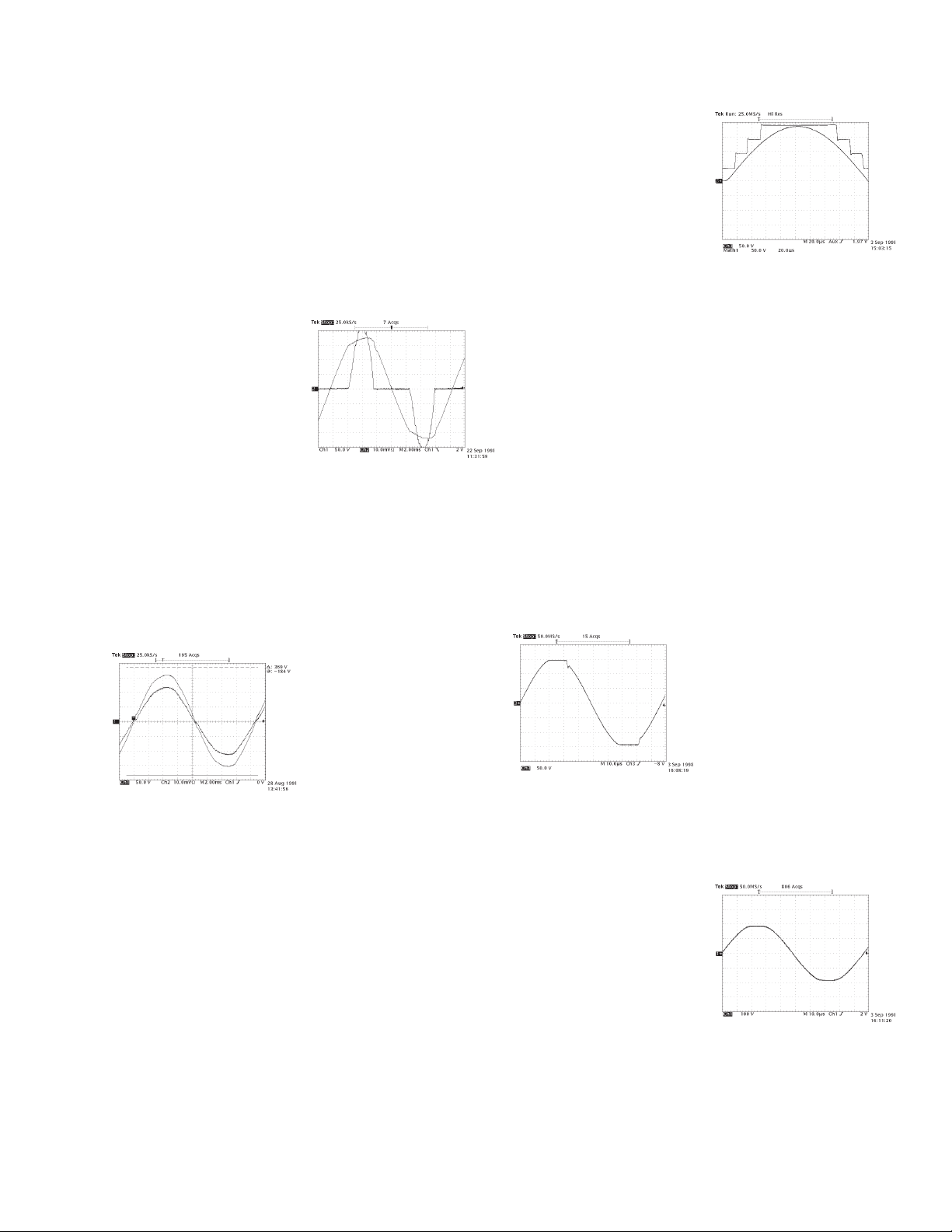
Figure 1.8. An amplifier with PFC
draws current throughout the
AC voltage waveform.
PFC
, had power factor correction to reduce
Figure 1.7. Amplifiers without
PFC draw current only at the
peaks of the AC voltage
waveform.
channel. The amplifier circuitry
automatically and instantaneously switches to the lowest
rail voltage that will allow the
reproduction of the audio
signal without discontinuity.
Each amplifier channel has its
own power supply. In addition,
each has a small “housekeeping” supply that manages the
turn-on functions before the
main power supply starts up.
PFC
susceptible to RF interference,
high-frequency oscillations, etc.
The audio signal passes through
a pre-clipper, which prevents
the audio signal from driving
the output section itself into
actual clipping. This maintains
damping on the channel output
even during clipping so that it
continues to tightly control the
loudspeaker motion, which is
something most amplifiers
cannot do. A defeatable clip
limiter on each channel reduces
signal level when clipping occurs; it does not prevent clipping, but
reduces the amount of distortion to inaudible or barely audible
levels.
An all-pass filter uses group delay to slow the audio signal by 4 µs,
but the class H steps are controlled by the undelayed signal. This
reduces IM distortion by ensuring that the steps are executed
before the audio signal in the output section reaches the transition
thresholds.
The audio signal voltage is converted into current by transistors
Q87 and Q89, to be precisely bifurcated into positive and negative
halves by the current steering circuitry. These current signals are
the controls for the output devices.
Figure 1.10. Most amps lose
feedback during clipping,
resulting in loss of damping and
in “clip sticking.”
Figure 1.9. The rail voltages of
the output section switch
among four tiers to reproduce
the signal faithfully while
maximizing efficiency.
The output devices are vertical
MOSFETs, which are commonly
used for very high power
switching because of their
power handling capability and
general nonlinearity. Using
them for linear audio amplification requires an unorthodox
approach. In these three
PowerLight amplifier models,
each channel has eight MOSFET
devices arranged in a full bridge
configuration. Each one has a
Audio circuitry
The audio inputs are balanced to offer a high amount of commonmode noise rejection. The input balancing is done using an
instrumentation amplifier arrangement, which uses a single op
amp, arranged as a voltage follower or buffer, on each leg of the
balanced input, driving a single op amp differential amplifier. The
degree of common-mode rejection is dependent on the close
matching of the impedance between each leg and ground and
around the differential amplifier. The circuitry uses 1% precision
resistors to ensure at least 40 dB of common-mode rejection.
The differential amplifier circuitry includes a first-order highfrequency roll-off, down 3 dB at 280 kHz (nearly four octaves above
the high end of the audio spectrum). This makes the amplifier less
Technical Service Manual 7
PowerLight 6.0 II, PowerLight 6.0
PFC
, and PowerLight 9.0
PFC
local management circuit called
a current cell that controls and
linearizes the device by
providing the necessary
compensation to make the
MOSFET’s conductivity track the
signal current.
Figure 1.11. The pre-clipping
scheme in the PowerLight 6.0
PFC
9.0
, and 6.0 II keeps the
output signal clean despite the
flat-topping of the waveform.
PFC
,
2. Servicing the amplifier
2.1 Mechanical disassembly and reassembly
Introduction
Replacing components will usually require removing the affected
modules from the amplifier chassis. The two channels each have
their own power supply module and audio module, and they share
the line filter assembly and the input, output, and display board
assemblies.
Within the chassis, the power supply modules are on the bottom,
and the audio modules are on top. Getting at a power supply
module requires removal of its audio module first.
The following instructions describe the procedure for removing
both audio and both power supply modules. However, if you only
need to work on one channel, you do not need to remove the
modules from the other.
Tools and materials needed
• Philips screwdriver
• Diagonal cutters
• Tie wraps
• Needle-nose pliers
• Adhesive rubber foot (one per channel), QSC part # QQQQQQQQ-QQ or equivalent
• 5/64” hex (Allen) key
• 11/32” nutdriver or socket wrench
• Isopropyl alcohol and a small brush
Disassembly
Removing the top cover
1. Disconnect the amplifier from AC power and allow at least 10
minutes for internal voltages to bleed down.
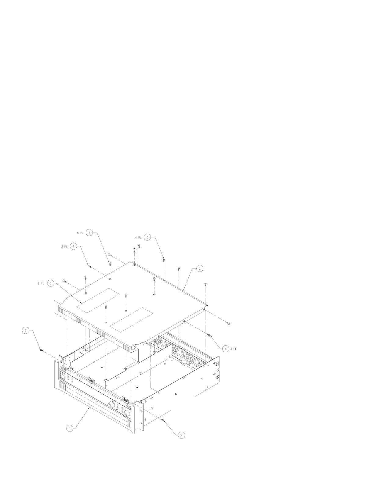
2. A total of 18 screws—six with pan heads and twelve with flat
heads—hold the top cover to the chassis. Using a Philips
screwdriver, remove them and set them aside. See Figure 2.1.
3. Lift the top cover up at the front until it clears the side rack ear
pieces, then lift it off the chassis. If the front of the cover is
bent or dented, make sure the front edge clears the two
display board headers.
Figure 2.1. Removing or installing
the top cover.
Key QSC Part Description Qty.
1
WP-000170-XX Chassis assy., PL 9.0 1
2
CH-000079-00 Top cover 1
3
SC-082051-PL Screw, #8-32 × 5/16”, pan head 6
4
SC-080051-PU Screw, #8-32 × 5/16”, flat head 12
5
PL-000104-00 Insulator, high volt. 2
8 QSC Audio Products, Inc.
TD-000083-00

(2 bundles)
Figure 2.2. Seven tie wraps.
Preparing the audio modules for removal
4. There are two fishpaper insulators on each audio module.
Remove them by lifting them straight up off the heat sinks. Do
not slide them forward or backward.
5. Cut the tie wraps in the seven locations shown in Figure 2.2.
6. Disconnect the display board header in front of each module.
7. Using needle-nose pliers, grasp one of the housekeeping
supply connectors and disconnect it from the modules (see
Figure X.X). Repeat for the other(s).
8. Disconnect the fan connections (two on each module).
9. Spread open the latches on the power
supply control interface connections and
disconnect the headers from the
modules.
10. Remove the two screws that secure the
audio module to the chassis partition.
One screw is at the corner near the
power supply connections, and the other
is about 6 cm (2.5 inches) behind the
housekeeping supply connections.
11. Locate the power supply connections, the
five screw terminals at the front of each
module. Loosen them and remove the
wires.
Figure 2.3. The connections to
Power supply
control (8-pin
header)
Power supply
(wires 0 through 4)
the audio module.
Fan (4-pin header;
2 pins per fan)
12. There may be an adhesive rubber foot
wedged in front of each module circuit board.
Grasp it with the needle-nose pliers and pull
it out.
Removing the chassis rear panel
13. Remove the four screws on the rear panel
(see Figure 2.4).
14. Tip the amplifier up on its right side (the side
opposite the power cord). There are three flat
head screws in a line along the center of the
side panel. Remove them.
15. Remove the two pan head screws on the rear
rack tab.
16. Set the amp back down and remove the two
pan head screws from the other rear rack tab.
17. Remove the two screws under the power
cord.
18. Tip the chassis rear panel back and disconnect the header from the input board.
19. Lift the fan wires clear of the heat sinks on
the audio modules.
From input
board
(detachable
latching header)
Housekeeping
supply
Display
board
(via multiconductor
ribbon cable)
Technical Service Manual 9
PowerLight 6.0 II, PowerLight 6.0
PFC
, and PowerLight 9.0
PFC
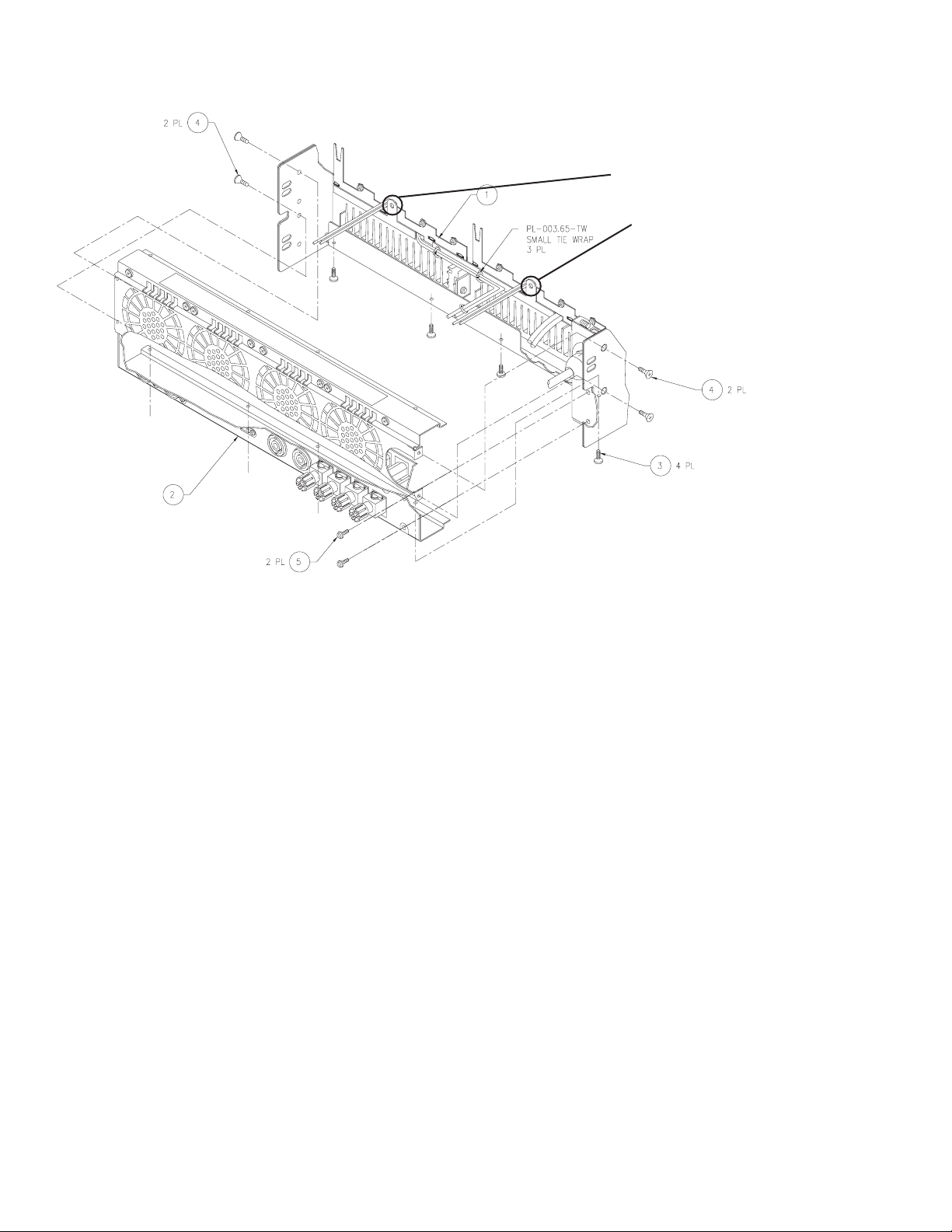
Figure 2.4. Removing or installing the
chassis rear panel.
Locations of
ground screws
for audio modules
Key QSC Part Description Qty.
1
CH-000078-00 Chassis, PL 9.0 1
2
WP-000172-00 Rear chassis assembly 1
3
SC-082051-PL Screw, #8 × 5/16”, pan head 4
4
SC-080051-PU Screw, #8-32 × 5/16”, flat head 4
5
SC-082051-PL Screw, #8 × 5/16”, pan head 2
20. Remove the chassis rear panel from the main chassis.
21. Cut and remove the tie wraps that secure the output wires to
the rear panel.
Removing the audio modules
22. There is a ground screw at the back of each audio module
(see Figure 2.4). Remove it.
23. Slide the audio module toward the front of the chassis so that
its keyed mounting holes are clear of the standoffs.
24. Lift up the back of the audio module slightly, then lift the
entire module clear of the chassis.
Removing the power supply modules
25. If you need to remove one or both power supply modules, you
will need to remove both audio modules. Invert one audio
module and set it on top of the other channel’s audio module,
then set them aside.
26. Straighten the five power supply wires on each channel.
27. Remove the three screws from the front of the chassis
partition.
28. Remove the side-facing screw from the front of the partition
on channel 1’s side.
29. Remove two black pan head screws from the center line of
the chassis partition.
30. Slide the chassis partition back, then lift up on the channel 2
side of it. Press down on the back of the partition, then lift it
clear of the chassis.
31. Remove the two screws at the front of the power supply
module.
32. Use a 5/64” hex (Allen) key to remove the screw at the rear of
the power supply module.
33. Use an 11/32” nutdriver or socket wrench to remove the two
nuts on the AC connection (a white and a black wire).
34. Slide the power supply module toward the rear of the chassis,
then lift it up and out of the amplifier.
Inspecting the power supply modules
35. Visually inspect the power supply module. Check the leads of
diodes D1 and D12, because they sometimes crack due to
flexing of the circuit board.
36. Using isopropyl alcohol and a brush, clean any dirty or charred
parts of the circuit board. Look for burned-off circuit board
traces, especially around the switching MOSFETs; missing or
damaged ones can be repaired using a trace repair kit. If the
10 QSC Audio Products, Inc.
TD-000083-00
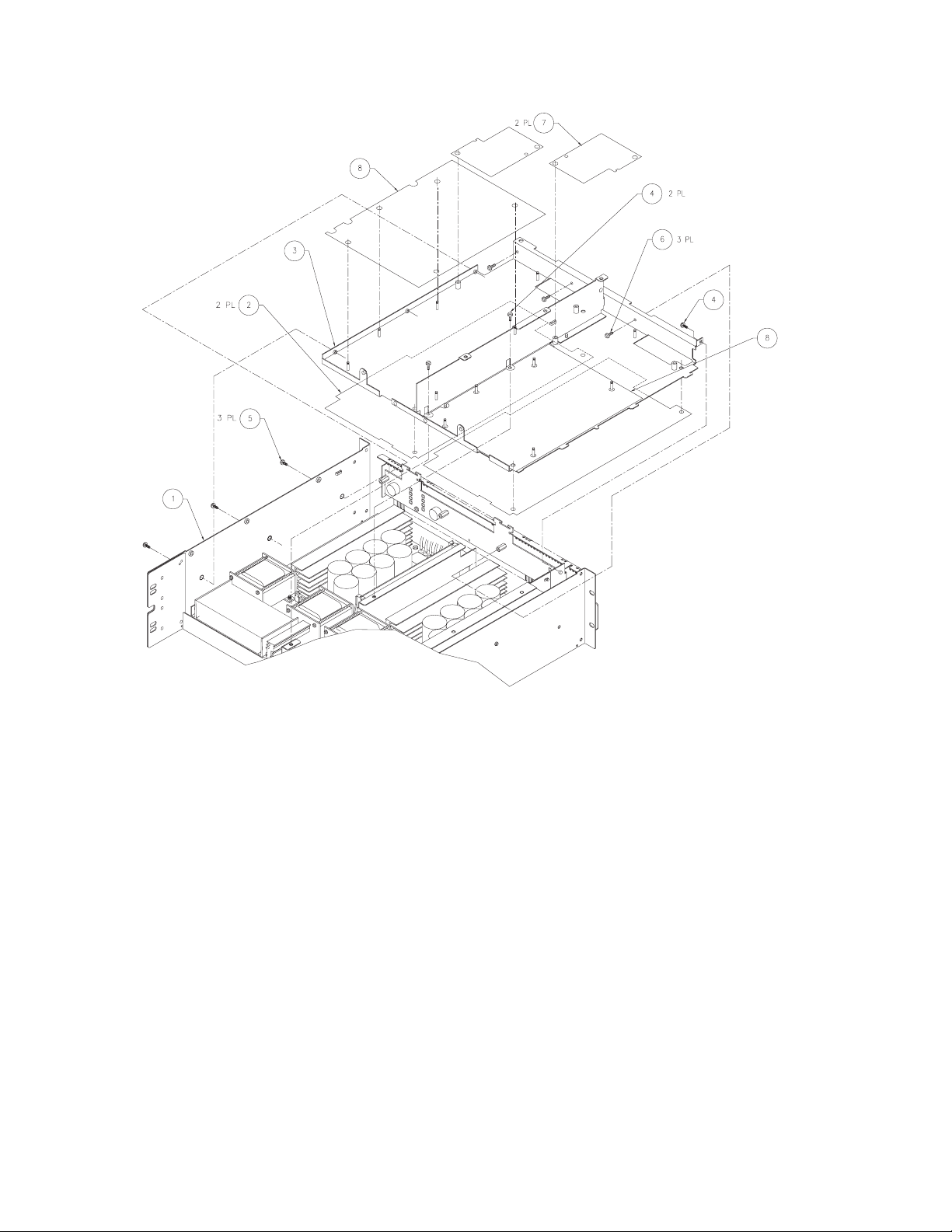
Key QSC Part Description Qty.
1
CH-000078-00 Chassis, PL 9.0 1
2
PL-000107-00 Heatsink insulator 2
3
CH-000080-00 Chassis horiz. partition 1
4
SC-080051-PS Screw, #8-32 × 5/16”, SEMS 3
5
SC-082051-PU Screw, #8-32 × 5/16”, pan head 3
6
SC-060042-PP Screw, #6-32 × 1/4”, SEMS 3
PL-000109-00 Insulator, mega platform 2
7
8
PL-000137-00 2
Insulator, amp rear bottom
Figure 2.5. Removing or installing the chassis partition.
circuit board is burned into the fiber layers or badly damaged,
replace the entire module.
See instructions for servicing the power supply module
elsewhere in this chapter.
4. Insert and tighten the two screws at the front of the module.
5. Install the chassis partition.
6. Insert and tighten the two screws along the center line of the
chassis partition.
7. Insert and tighten the side-facing screw at the front of the
Reassembly
Reassembling the amplifier chassis is essentially reversing the
order of the disassembly process.
Installing the power supply module
1. Align the keyed slots in the power supply module circuit board
with the chassis standoffs. Watch out for the fish paper
insulators, which may get caught underneath. Drop the
module into place on the standoffs and slide it forward.
2. Using the 11/32” nutdriver or socket wrench, attach the AC
wires to the module. The black wire attaches in front (closer
to the front of the amplifier chassis) of the white one.
3. Using the 5/64” hex (Allen) key, insert and tighten the screw
at the rear of the power supply module.
Technical Service Manual 11
PowerLight 6.0 II, PowerLight 6.0
PFC
, and PowerLight 9.0
PFC
chassis partition on the channel 1 side.
8. Insert and tighten the three screws at the front of the chassis
partition.
Installing the audio modules
9. Place the audio modules in position.
10. Insert and tighten the ground screw at the back of each
module (see Figure 2.4).
11. With new tie wraps, secure the output wires to the chassis
rear panel.
12. Loosely insert one screw on each end of the chassis rear
panel, then tighten them both.
13. Insert and tighten the other two screws.
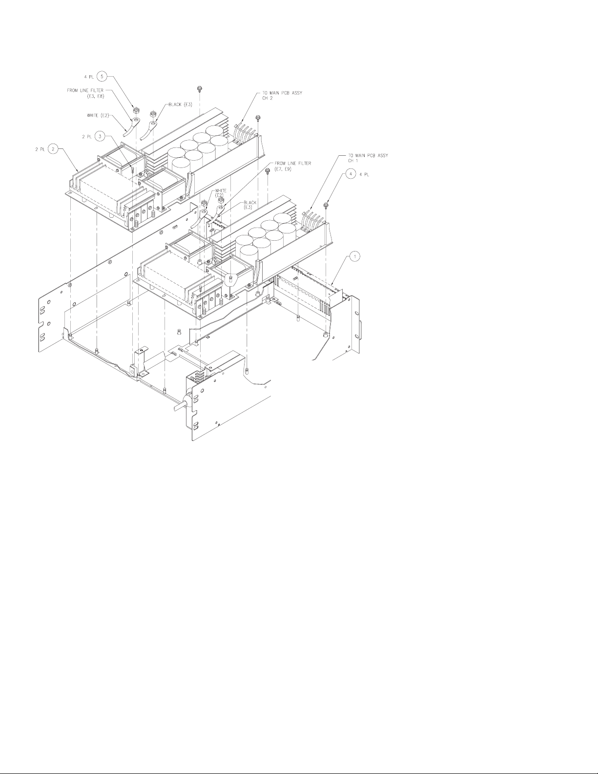
Figure 2.6. Removing or installing the
power supply modules.
Key QSC Part Description Qty.
1
CH-000078-00 Chassis, PL 9.0 1
2
WP-000173-00 Power supply PCB assy. (120V) 2
WP-000180-00
3
SC-040155-00 Screw, #4-40 shoulder hex head 2
4
SC-060042-PP Screw, #6-32 × 1/4”, SEMS 4
5
NW-080500-KP Keps nut, #8-32 4
Power supply PCB assy. (230V) 2
14. Insert and tighten the two screws under the power cord.
15. On each audio module, tuck the two fan wires into one or two
slots of the heat sink. Reconnect both to the four-pin header
on the audio module.
16. Reconnect the input headers to the audio module.
17. Tip the amplifier up on its right side (the side opposite the
power cord). Insert and tighten the three flat head screws in a
line along the center of the side panel.
18. Set the amp back down. Reconnect the five power supply
20. Reconnect the housekeeping supply wires at the front of the
module.
21. Using five new tie wraps, secure the wire bundles to the
chassis partition at or near the front of the amplifier. Each
secures one bundle, except for the one at the center, which
secures two.
22. Using two new tie wraps, re-connect and secure the two
headers to the display board.
23. Re-install the top cover of the amplifier.
wires, 0 through 4, to their respective screw terminals at the
front of the module. Make sure they are placed in the proper
sequence—from left to right, as viewed from the front of the
amplifier:.0, 1, 2, 3, and 4.
19. Reconnect the power supply control interface. Make sure the
latching wings of the board-mounted connector are up all the
way.
12 QSC Audio Products, Inc.
TD-000083-00

Key QSC Part Description Qty.
1
CH-000078-00 Chassis, PL 9.0 1
2
HW-000079-00 Hex standoff #6-32 x 9/16” 5
3
WP-000176-00 Display PCB assy. 1
4
SC-060042-PP Screw, #6-32 × 1/4”, SEMS 2
5
HW-060080-HW Hex standoff #6-32 x 1/2” 3
6
PL-000054-00 Knob fab. 2
Figure 5.7. Removing or installing the display board.
2.2 The display board
The display board contains the signal metering, clip, power, and
status LEDs. It also holds the two gain potentiometers. LED failures
are very rare, but you will need to remove the board if the gain
pots become damaged or badly contaminated. See Figure 2.7.
2.3 AC line filter
The AC line filter is an important part of the amplifier because it
reduces noise and interference from the internal switching
circuitry to prevent its radiation into the AC wiring. It also contains
part of the housekeeping supplies for the two audio modules;
without the housekeeping supplies, the amplifier’s power supply
modules will not start up even if they are in working order.
The line filters are the same among the three amplifier models,
but the 120-volt and 230-volt versions are not interchangeable.
See Figure 2.8.
Technical Service Manual 13
PowerLight 6.0 II, PowerLight 6.0
PFC
, and PowerLight 9.0
PFC
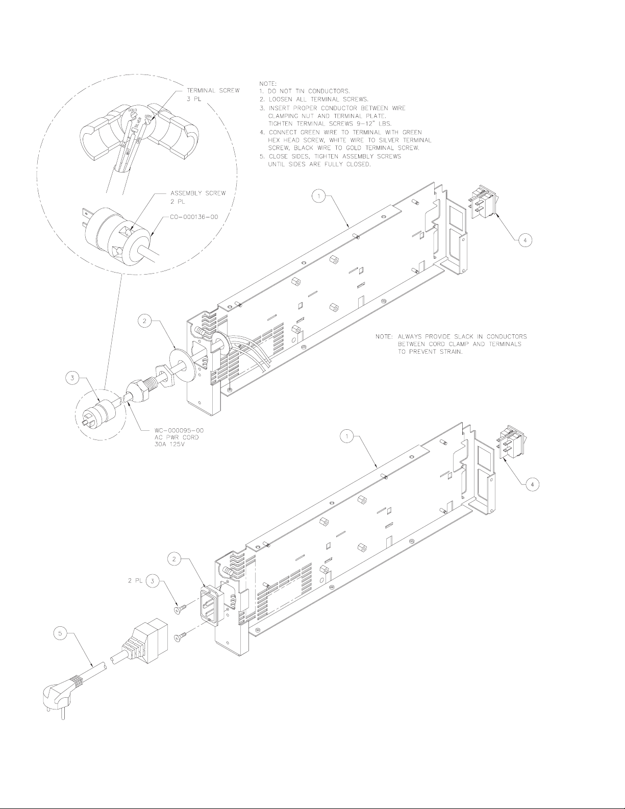
120V version
230V version
Key QSC Part Description Qty.
1
WP-000177-00 Line filter PCB assy. 1
2
NW-000021-03 Flat Washer 1
3
WP-000042-00 AC power cord assy., 30A 125V 1
4
SW-000027-SW Switch AC 1
Key QSC Part Description Qty.
1
WP-000181-00 Line filter PCB assy. (230V) 1
2
C0-000099-00 Connector line side flange 1
3
SC-083061-PU Screw, #8-18 × 3/8”, flat head 2
4
SW-000027-SW Switch AC 1
5
WC-000022-00 Cord set 3 cond. 16A 250 VAC 1
Figure 2.8. Assembly details of the AC line filter.
14 QSC Audio Products, Inc.
TD-000083-00
2.4 Power supply servicing
Bench testing power supply modules
The housekeeping supplies provide electrical power to certain
control circuitry in their respective audio channel modules. The
control circuitry in turn enables the power supply module to
operate. Thus, a power supply module normally will not operate
when it is not connected to an audio channel.
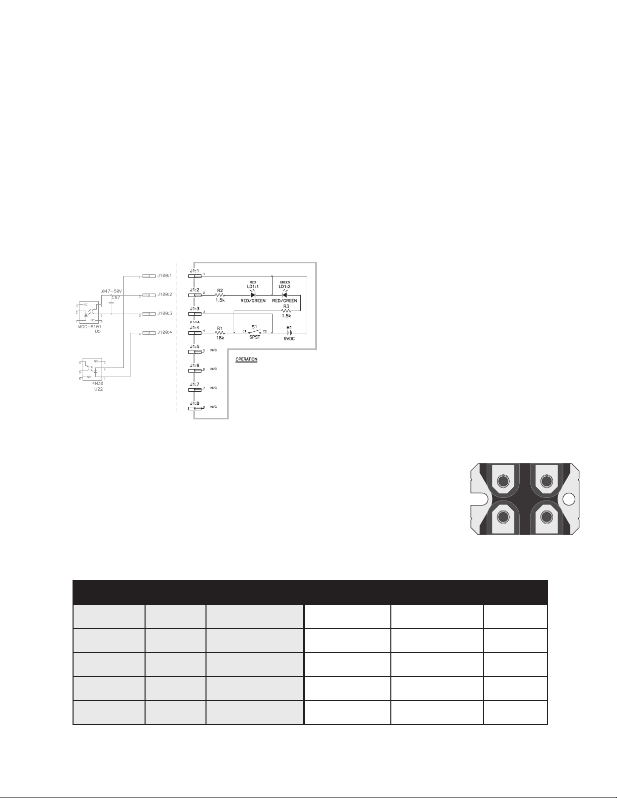
The remote control circuit shown in Figure 2.9 allows the power
supply module to operate without an audio channel module
connected. This is useful for verifying the power supply’s operation
independently of other amplifier circuitry.
POWER SUPPLY TEST
REMOTE CONTROLLER
THIS REMOTE CONTROL IS USED TO TURN ON THE
PFC POWER SUPPLY VIA J100 ON THE CONTROLLER
BOARD.
CLOSING POWER SWITCH S1 ENABLES THE POWER
SUPPLY, AND LED LD1:2 WILL GLOW GREEN.
THE AC INPUT VOLTAGE APPLIED TO THE PS
POWER SUPPLY
CONTROLLER BOARD
MODULE REACHES THE TURN-ON THRESHOLD (65
VAC FOR 120V UNIT OR 130 VAC FOR 230V UNIT),
LED1:1 WILL ALSO LIGHT, AND THE RESULTING
COLOR WILL BE YELLOW-ORANGE.
Figure 2.9. Remote controller for power supply testing.
Parts list
• 8-pin header (J1)
• 9-volt battery (B1)
• SPST switch (S1)
• Three-lead tri-color LED (LD1)
• 18 kΩ resistor (R1)
• Two 1.5 kΩ resistors (R2 and R3)
Replacement parts
WHEN
Replacing switching MOSFETs in PFC models
Replacing the power MOSFETs and their associated components
requires that the power supply modules be removed from the
amplifier.
T ools and materials required:
• Soldering iron
• Rosin-core solder (60/40 or 63/37 eutectic type)
• Long-nose pliers
• #1 and #2 Philips screwdrivers
• Thermal grease (heat sink compound)
• Small diagonal cutters
• Desoldering equipment or solder braid
• Micro-torque wrench with 9/64” Allen (hex) and #1 Philips bits
If fuse F1 on the power supply module’s printed circuit board (PCB)
is blown, you will also need a 1A 250V 5×20 mm slow-blow fuse
(QSC part # MS-000113-00) to replace it with. Also, the alumina
insulator between the diodes and the heat sink is very fragile and
often breaks when the diodes are removed; replace it with QSC
part # PL-000085-00.
To ensure that the devices will share power equally, the four
MOSFETs must have similar V
. For a set of four matched
DSS
MOSFETs, as pre-sorted by QSC production, order QSC part #
WP-000056-00.
Procedure: replacing Q1, Q2, Q3, and Q4
1. Remove the heat sink assembly to which the MOSFETs are
attached.
To do this, remove the clamps on the four diodes (D1, D2, D7,
and D8) to free them from the heat sink. Keep the two mica
insulators (from between the
diodes and clamps) and set
them aside for when you
reassemble the heat sink and
diodes later; they are fragile,
so be careful handling them
but replace any that are
damaged. The QSC part
number is PL-000059-00.
Remove the alumina insulator
Figure 2.10. Bottom view of a
MOSFET
ecnerefertraP #trapweN noitpircseD #trapdlosecalper… noitpircseD ?sledomhcihW
4Q&,3Q,2Q,1Q
8R&,7R,6R,5R
8D&,7D,2D,1D
8D&,7D,2D,1D
02C
00-881000-DQ TEFSOMA5505N55FXI
01-10574.-ER 57.4 ΩΩΩΩΩ rotsiserttaw-¼
00-381000-DQ edoid80SPE06
00-281000-DQ edoid21SPE06
00-900014-AC roticapacV052Fµ1.0
00-911000-DQTEFSOMA8405N84FXI
01-20001.-ER1Ω rotsiserttaw-¼
00-621000-DQedoidA60-06IESD
00-761000-DQedoid21-06IESD
00-004743-ACroticapacV004Fµ740.0
sledomllA
sledomllA
ylnosledomV021
ylnosledomV032
sledomllA
Technical Service Manual 15
PowerLight 6.0 II, PowerLight 6.0
PFC
, and PowerLight 9.0
PFC

“Diode”
end of
heat sink
Figure 2.10: The heat sink assembly, with all four MOSFETs
attached. The “diode” end of the heat sink is at right; the slots in
the MOSFETs would face to the left.
(from between the diodes and the heat sink); it is extremely
fragile, so it is best to replace it during reassembly with a
new one.
Then remove the 16 screws that attach the MOSFETs to the
printed circuit board (PCB); if the MOSFETs are blown, some
of the mounting screws may be melted or damaged. The new
MOSFETs come with new mounting screws with captive
washers, so there is no need to save old ones for reuse.
Remove the other four mounting screws so that the heat sink
assembly is free from the circuit board. Set the hardware
aside.
Find where the twisted wire lead from the heat sink’s thermal
sensor attaches to a pair of pins on the board, and unplug it.
Detach the gate drive cable, which is an 8-conductor ribbon
cable that plugs into an 8-pin header. Lift the heat sink and
MOSFET assembly from the board. If the strip of fishpaper
(Figure 2.11) remains stuck to the PCB, leave it there; if it
comes loose, set it aside for re-assembly later.
Figure 2.11. The silk screen on the circuit board shows the
correct orientation of the MOSFETs. This photo also shows
the four resistors (R5–R8) to be replaced.
2. Remove the MOSFETs from the heat sink. Thoroughly clean the
old thermal grease off the heat sink. Apply fresh thermal
grease to the new MOSFETs (QSC part # QD-000188-00) and
attach them to the heat sink.
Make sure the new MOSFETs are correctly oriented. One end
of each MOSFET has a mounting hole, while the other has an
open-ended slot (see Figure 2.9). Each MOSFET must be
away
mounted so the slot end faces
from the diode end of the
heat sink (see Figure 5.11). Try to get the MOSFETs evenly
spaced and as close to perfectly in line as you can. The silk
screen print on the circuit board (see Figure 5.12) shows the
correct orientation.
Tighten the MOSFET mounting screws to 32–35 lb-in (3.6–4.0
N-m) torque. Do not over-torque them.
3. Remove the four diodes on the circuit board (D1, D2, D7, and
D8). See Figure 2.12.
4. Check the value and rating labeled on capacitor C20 (see
Figure 2.13). If it is not a 0.1 µF 250V capacitor (early modules
will have the original 0.047 µF 400V component instead),
replace it with QSC part # CA-410009-00.
5. Remove resistors R5 through R8 (see Figure 2.11) and replace
them with 4.75Ω ¼-watt resistors (QSC part # RE-.47501-10).
6. Set the MOSFET and heat sink assembly upside-down and
place the PCB on top of it. Make sure all the threaded holes in
the heat sink and the MOSFETs line up exactly with the holes
in the board. If any MOSFETs don’t line up, reposition them so
they do because misaligned mounting screws can damage
them when tightened.
Make sure the fishpaper strip is in place, and then reattach
the MOSFET and heat sink assembly to the PCB. Make sure
you use the correct screws and washers in each location.
Tighten the four heat sink screws to 32–35 lb-in (3.6–4.0 N-m)
torque and the MOSFET mounting screws to 12 lb-in (1.4 Nm). Do not over-torque them.
CAUTION: Overtightening its mounting screws will destroy a
MOSFET. When tightening a screw, use the split lockwasher
as a visual guide; as soon as it is flattened, the screw is tight
enough.
Plug the thermal sensor lead onto its two pins on the circuit
board.
7. Clear any solder from the circuit board holes for the four diodes.
Apply a thin coating of new thermal grease to both sides of
the alumina strip and set it in place on the heat sink.
Insert the four new diodes (120V models: QSC part #
QD-000183-00; 230V models: QSC part # QD-000182-00) into
their holes in the PCB, but do not solder them in place yet.
Then set the two mica insulators in place over the diodes
(they will overlap in the middle), and clamp and fasten the
diodes to the heat sink; tighten the screws to 32–35 lb-in
(3.6–4.0 N-m) torque. Do not over-torque them. As you do
16 QSC Audio Products, Inc.
TD-000083-00

Figure 2.12. These four diodes need to be replaced.
this, make sure the diodes are straight and evenly spaced, and
reposition them if necessary.
8. Solder the four diodes to the circuit board.
9. Reattach the gate drive cable.
10. Check the fuse (see Figure 2.14). If it is blown, replace it with
a slow-blow 1A 250V 5×20 mm fuse (QSC part #
MS-000113-00).
11. Repeat the procedure for the other channel’s power supply
board if it also has failed or is to be updated.
Capacitor C20
Figure 2.13. Capacitor C20 may also need
replacement. See the text.
Fuse F1
Figure 2.14. Fuse F1 may need replacing.
Suggestions for troubleshooting
If you are repairing a failed power supply module and not simply
upgrading a working one, you should determine whether other
components have also failed.
Typical collateral failures around PFC power supply module failures
include:
Blown high rail diodes: Check D12 and D14 for sooty or
blackened thermal grease around their edges or for any other
signs of damage. If you suspect that they might be damaged,
remove them from the circuit board and check them with the
diode test function on a DMM. Replace them if necessary
(QSC part # QD-000126-00). These diodes are clamped onto
the other heat sink, at the end next to the power transformer.
If you remove the diodes, thoroughly clean away the old
thermal grease from that portion of the heat sink and from
the mica insulators; apply fresh thermal grease when you
reassemble or replace them.
Blown driver ICs: The two MIC4452BN MOSFET driver ICs, U1
and U3, are under the MOSFET heat sink. Frequently, when
MOSFETs fail, the driver IC associated with the transistor(s)
fails, too. The IC’s QSC part # is IC-000064-00.
Fuses: Conditions that cause the MOSFETs to fail also frequently
cause the fuses on the AC line filter to blow. The filter circuit
board runs along the side of the amplifier between the AC power
cable and the AC power switch. Each channel has two fast-blow
ceramic AC fuses, for a total of four (120V models: 125V 25A,
QSC part # MS-000112-00; 230V models: 250V 15A, QSC part #
MS-150250-FU). Check them and replace any that are blown.
Also on the AC line filter board are the housekeeping supplies
for each channel; if they do not work, the channels will not
start even if the power supply modules are in perfect working
order. The housekeeping supplies each use a 250V 1A slowblow fuse (QSC part # MS-000113-00).
Technical Service Manual 17
PowerLight 6.0 II, PowerLight 6.0
PFC
, and PowerLight 9.0
PFC
Adjusting and calibrating the power supply
module
Adjusting and calibrating the power supply card will help ensure
the success of the repair; this portion of the service bulletin
describes a series of five procedures for doing so. Because of the
specialized nature of the power supply fixture required for these
procedures, it can only be performed at the QSC factory by trained
personnel. Follow these procedures exactly and in order.
There are four trimpots, VR1–VR4 (see Figure 2.14), on the
controller card that must be adjusted correctly before reinstalling
the power supply in the amplifier:
VR1 On the PL 9.0
sets V
OUT
/26.6.
PFC
, this trimpot sets V
/32; on the PL 6.0
OUT
PFC
, it
VR2 This trimpot is for balancing the transformer to the PFC circuitry.
VR3 This trimpot sets the maximum 2-ohm output power. For the
PFC
PL 9.0
, it will be set for 4500 watts @ 2 ohms at 2 kHz; for
the PL 6.0
PFC
, it will be set for 3600 watts @ 2 ohms at 2 kHz.
VR4 This trimpot sets the power supply’s idle voltage. For the PL
PFC
9.0
, it will be set for 191.3 volts DC; for the PL 6.0
PFC
it will
be 166.5 volts DC.
VR4
VR3
VR1
VR2
Figure 2.15. The locations of the four trimpots, VR1–VR4
Tools and materials needed:
• PFC power supply fixture with external power supply and CMP
(Control-Monitor-Power) box
• Two digital multimeters (DMM #1 and #2) with clip-on leads
• Digital multimeter (DMM #3) with clamp-on AC current probe
• 0–240 VAC Variac™, Powerstat™, or similar variable AC
transformer; 60 amperes or higher rating, with RMS voltage
and current metering
• 120 VAC power (for the fixture’s housekeeping supply)
• Four-channel oscilloscope with ×1/×10 probes
• Oscilloscope with differential probe
step 10 of the V
procedure)
OUT
• Small pocket-type flat-blade screwdriver
• Grounded anti-static work surface
• Audio Precision (AP) workstation with PFC test
procedure files* and 2-ohm load resistor banks
(mimimum power handling capacity: 1250 watts per
8-ohm resistor; 5000 watts total in 2-ohm configuration).
*The four AP test procedure files are available on the QSC Technical
Support CD-ROM: Pfcxf.tst; Pfcpwr2k.tst; Pfcpwr20.tst; and
Pfctherm.tst.
(optional; see
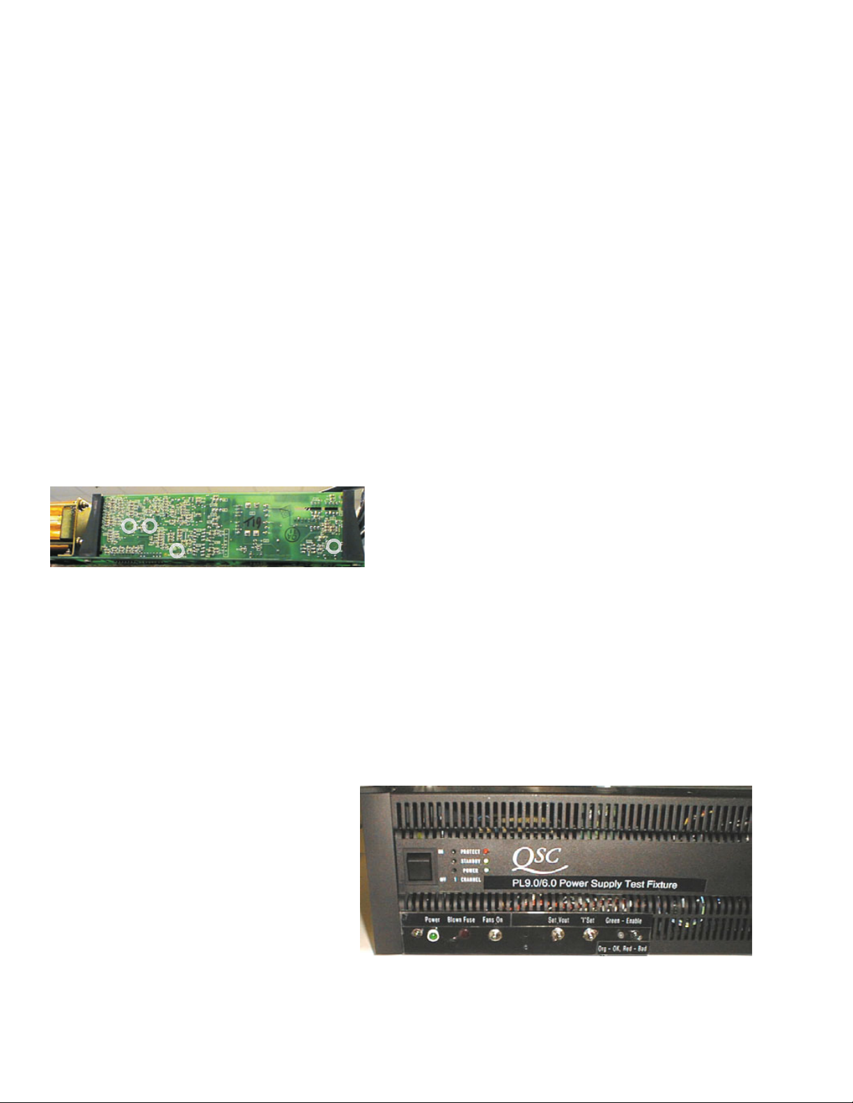
Figure 2.16. The front of the fixture. The amplifier channel’s gain control is
to the right, out of the picture
The PFC power supply fixture
The PFC power supply fixture is a special test bed for PowerLight 6.0
and 9.0 supply modules. It has the necessary connections and
indicators for adjusting, calibrating, and testing the modules. It
also contains one audio channel of a PowerLight 9.0 to allow
testing of the module’s capability to power an actual amplifier
channel. The fixture is custom built by QSC.
Front panel switches and indicators
From left to right (Figure 2.14):
• Power switch. For the AC lines to the power supply module
being tested.
• Power indicator. It lights when the fixture is connected to AC
power and is turned on.
• Blown fuse indicator. Connected across the large fuse under
the door in the top of the fixture chassis, this indicator will light
if the fuse blows. The fuse, however, is merely a backup in case
the CMP box’s solid-state electronic fuse malfunctions.
• Protect, Standby, and Power indicators. In the portions of
the test that use the amplifier channel, these LEDs function just
as they do on a regular amplifier.
• Fan switch. Some portions of these procedures require the
module fans running, and others need them off.
• “Set V
• “I
for checking the module’s I
• “I
module’s I
Rear panel switches and attachments
From left to right (Figure 2.15):
• Audio input. This is where to connect the signal output from
the AP workstation.
• DC high rail outputs. These are two pairs of red and black
binding posts, and they carry the DC output of the supply
module’s high rails. Connect DMM #1 to one of these sets of
binding posts.
• Audio output. This Neutrik Speakon connector carries the
audio output of the fixture’s amplifier channel. Connect this
” switch. This switch is used for the first procedure.
OUT
” switch. This switch also is used in the first procedure
SET
” indicator. This tri-color LED indicates the status of the
SET
circuit.
SET
circuit.
SET
18 QSC Audio Products, Inc.
TD-000083-00
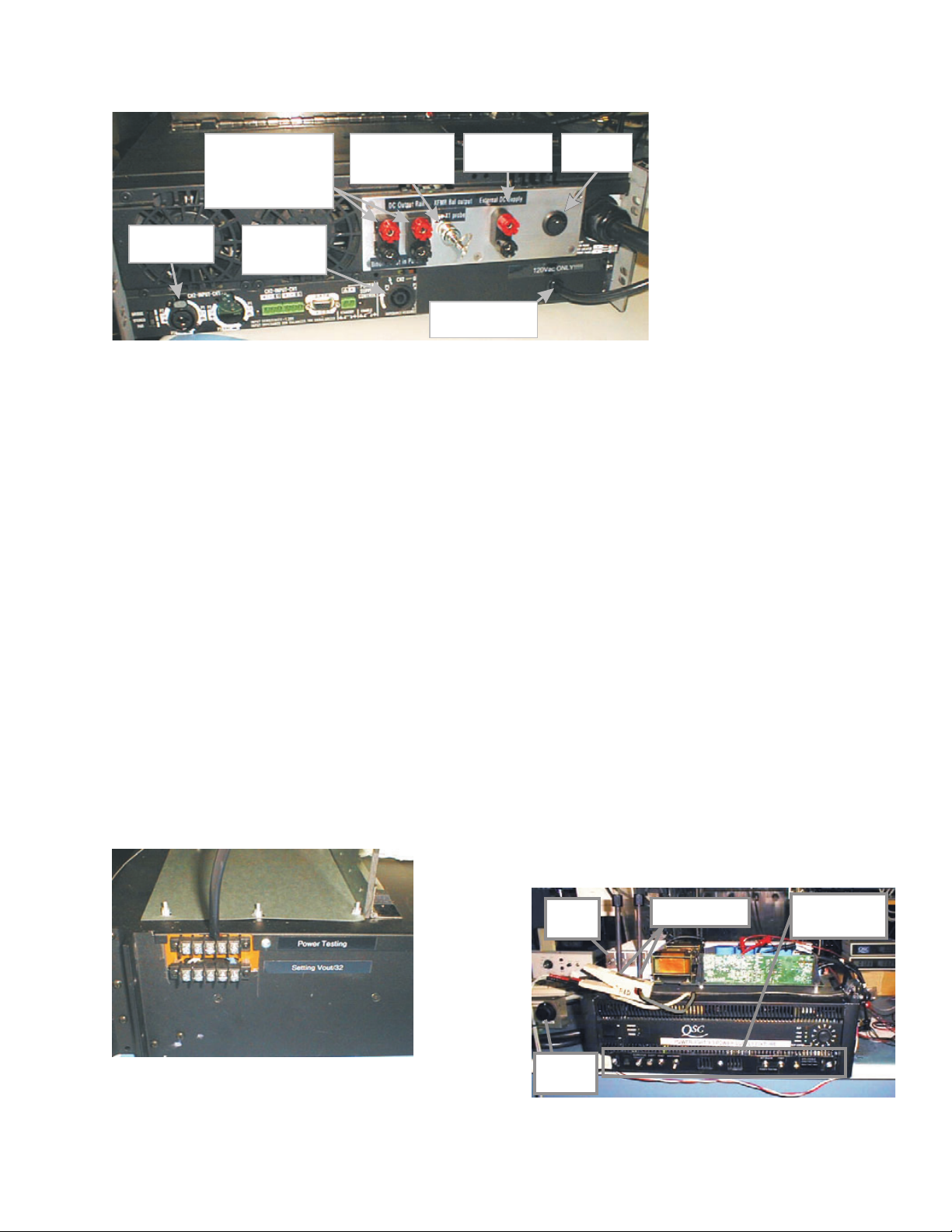
Audio signal input
from Audio Precision
workstation
DC high rail outputs: for
PFC PFC
PL 9.0 ; for PL 6.0
Red = +; Black = -
The two sets of binding posts are
in parallel. Connect DMM #1 to
191.3 V
166.5 V
one set.
Audio signal output
to Audio Precision
workstation and load
resistors
Figure 2.17. The fixture’s rear panel.
Transformer flux sample
for balancing procedure.
Connect to oscilloscope
using ×1 probe.
(Do not connect to Variac!)
Connect to external DC
supply. Watch polarity:
Red = +; Black = -
120 VAC for fixture's
housekeeping supply
Power switch for
housekeeping
supply.
• Upper barrier strip. Connect the
DC rail wires to the upper barrier
strip for the other procedures.
• Control connection. Above the
barrier strips is a multiconductor
cable that connects to the 8-pin
header on the controller card of the
power supply module under test.
• AC wires. Located at the top of the
front panel, these two wires connect
to points E2 and E3 on the supply
module.
output to the AP workstation and to the load resistors.
• Transformer flux sample. Connect the tip of an oscilloscope’s
×1 probe to the exposed conductor at the tip of this attachment, and connect the probe’s reference clip to the loop. This is
used in the transformer balancing, the third procedure in the
supply module adjustment and calibration.
• DC supply input. This dual binding post set is for connecting
the fixture to the external power supply.
• 120 VAC power cord. This connects to a regular AC outlet and
provides power for the fixture’s “housekeeping” supply, which
powers the various circuits and indicators.
• Housekeeping supply power switch. This small rocker
switch lets you turn off the housekeeping supply when the
fixture is not in use.
• Fixture power cord. This large power cord connects to the
Variac and provides AC power for the power supply module
under test.
Other attachments
See Figure 2.17.
• Lower barrier strip. Connect the supply module’s five black
DC rail wires to the lower barrier strip’s terminals for the first
procedure, setting V
OUT
.
Procedure 1 of 5: Setting V
OUT
1 Turn off all power to the fixture and turn the Variac all the
way down. Set the power supply module in place atop the
fixture, as shown in Figure 2.18.
2 On the test fixture, set switches V
/32 and I
OUT
SET
in the
up
position. Turn off the fan switch.
3. On the power supply module, disconnect the gate drive cable
(Figure 13).
4. Connect the two AC line wires to the stud terminals on the
PCB: white to E2 on the left, black to E3 on the right. Use the
long insulated threaded posts to secure the wires to the
terminals.
5. Connect the power supply module’s five black DC output
wires, labeled 0 through 4, to the screw terminals on the
lower
barrier strip (Figure 10). Keep them in order; do not
cross any of them.
6. The external power supply has two dual banana sockets—one
is labeled
dual banana plug to the external power supply’s
active
and the other,
dummy
. Connect the fixture’s
active
socket.
7. Plug the AC lines for both the external DC supply and the
fixture into the Variac.
8. Set the CMP boxe’s electronic fuse to a trip threshold of 5
amperes.
Switches and
LED indicators
Figure 2.18. The two barrier strips. Use the lower
one for the first adjustment (setting V
/32 or V
OUT
OUT
Ext. DC
AC connection
supply
Solid-
/
state fuse
26.6), and the upper one for the other adjustments. Figure 2.19. The power supply module loaded onto the test fixture.
Technical Service Manual 19
PowerLight 6.0 II, PowerLight 6.0
PFC
, and PowerLight 9.0
PFC
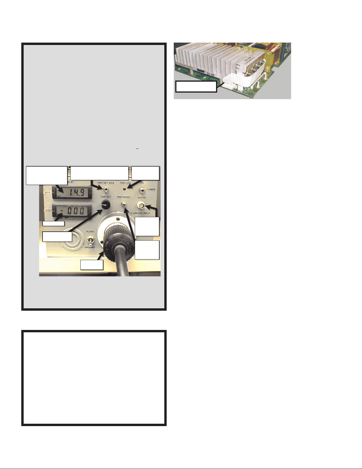
The CMP box
The CMP box has two digital panel meters that monitor AC
voltage and current and a solid-state electronic AC fuse that
can be set to trip specific current levels from 0 to 100
amperes.
To set the current trip level, flip the trip set switch down;
the AC ammeter will then read the trip current setting. Use
the trip set knob to adjust the desired trip point, then flip
the switch up.
The BNC jack provides an AC voltage proportional to the AC
current: 100 mV RMS = 1.0 ampere RMS. This is useful in
the transformer balancing procedure because it allows the
use of an external voltmeter with finer resolution (>3 decimal
places) than the panel ammeter has.
Trip set switch up:
reads AC current;
Trip set switch down:
reads trip current setting
AC voltage
Adjusts trip current
of solid state fuse
Trip set switch:
for normal solid state fuse function;
UP
to set solid state fuse trip
DOWN
0–280 VAC in
from Variac
Figure 2.20. The CMP box. The variable AC outlet for
the test fixture is on the back of the box.
Indicates that the
solid state fuse
circuit has tripped
AC current
sample for
external DMM
100 mV = 1.0 A
Press switch
down and back
up to reset the
solid state fuse.
Gate drive cable
Figure 2.21. The gate drive cable for the MOSFETs.
Disconnect it here for the V
9. Connect DMM #1 to one set of the parallel DC V
procedure.
OUT
terminals
OUT
on the back of the fixture. Connect DMM #2 to the controller
card, with the ground or reference lead on the tab of U8, a
+12V regulator, and the hot lead on the left leg of capacitor
C34. On the board, this point is labeled “VOUT/32.”
10.
Note: this step is optional because the replacement diodes
specified in this bulletin do not have the leakage problems
that many of the original fast diodes had.
Through a differential probe, connect an oscilloscope input between resistor R31
(labeled “OSC”) and ground; this will allow you to view the
output of the diodes to see if any are leaky.
11. Turn the fixture power switch on. Turn up the Variac gradually
until DMM #1 reads 190 volts DC (for the PL 9.0) or 166 volts
(for the PL 6.0). You don’t need to measure the AC voltage
from the Variac yet.
12. Adjust VR1 to obtain a reading on DMM #2 of 5.94 volts DC
(for the PL 9.0) or 6.20 volts DC (for the PL 6.0).
13. Flip the I
switch lights green or orange, I
switch down. If the LED indicator next to the
SET
is good; if red, it is bad and
SET
should be rejected for controller board replacement or repair.
14. Turn down the Variac all the way. Turn off the fixture’s AC
switch. Unplug the external supply’s AC line from the Variac.
15. Set the I
SET
and V
/32 switches
OUT
down
. Remove DMM #2’s
leads from the controller card.
16. Wait a few seconds for the capacitors to discharge and DMM
#1’s voltage reading to drop to 60 volts or less.
Important note about repaired PFC power
supply modules
After repairing a failed power supply module that had
already been calibrated before its failure, either in production or in Technical Services, the VOUT/32 and VOUT @
idle voltages in Procedure 1 only need to be checked and
not fully adjusted, unless the measured high rail voltage is
not 191.3 volts, ±1.5 volts, for the PL 9.0 or 166.5 volts, ±1.5
volts, for the PL 6.0. If the high rail voltages are outside this
range, then the module will require full adjustment and
calibration.
Procedure 2 of 5: Adjusting idle voltage
1. Re-attach the gate drive cable on the power supply module.
Also, disconnect the five DC rail output wires on the right end
of the module from the lower barrier strip and attach them to
the corresponding screw terminals on the upper barrier strip.
Make sure the screw connections are tight and secure.
2. Turn the fixture’s AC switch on and turn the Variac up to the
appropriate AC voltage: 120 volts AC for a 120V module, or
230 volts AC for a 230V module. The power supply will turn
on and begin to draw current when the AC voltage reaches
about the halfway point.
3. Adjust VR4 to obtain the a reading of 191.3 volts DC (for the
PL 9.0) or 166.5 volts DC (for the PL 9.0) on DMM #1.
20 QSC Audio Products, Inc.
TD-000083-00
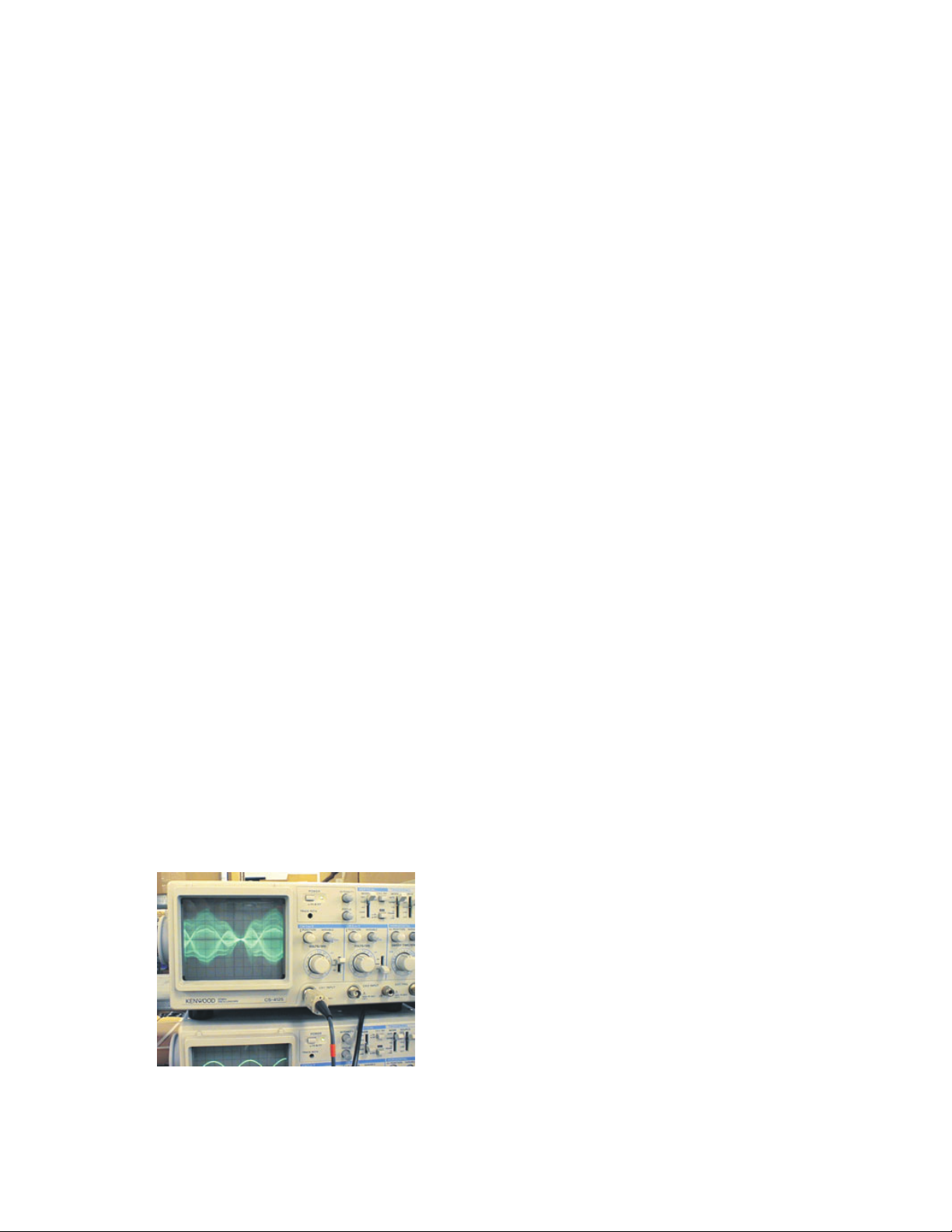
Procedure 3 of 5: Adjusting transformer balance
This is done in three stages. In the first two, watch the transformer flux “bubble” waveform on the oscilloscope, and on the
third, adjust the AC current to a minimum. To prevent overcurrent
cutback due to undervoltage, adjust the Variac to 130 volts for
120-volt modules or 260 volts for 230-volt modules.
1. Set the CMP box’s electronic fuse to a trip threshold of 20
amperes (for a 120V module) or 10 amperes (for a 230V
module) and turn on the fans.
2. Start the PFC test file (Pfcxf.tst) on the AP workstation. It will
put out a 2 kHz sine wave at 0.1 volt RMS and will switch the
load resistance to 2 ohms. Turn the fixture’s gain control all
the way up.
3. Step the signal level up in 0.1 volt increments and watch the
transformer flux “bubble” signal on the oscilloscope (vertical
scale: 20 or 50 V/div; horizontal scale: 1 or 2 ms/div; ×1 scale).
At each step, adjust VR2 to get a smooth, balanced signal.
See Figure 14. There should be no spurious oscillations or
noise visible.
4. When the audio signal reaches a particular level, the CMP box’s
electronic fuse will trip. Set the audio signal back to 0.1 volt.
5. Reset the trip point to 40 amperes (for a 120V module) or 20
amperes (for a 230V module) and repeat steps 2 and 3. The
electronic fuse should trip at about 2.8 kW of output
(measured on the AP)
,
with approximately 1.4 volts input.
6. Reduce the AP’s signal level to 0.1 volt. Reset the electronic
fuse and increase the signal level so that the output is about
2.5 kW. Gently adjust VR2 to null the AC current on DMM #3
to a minimum.
7. Turn the Variac down to zero and set the electronic fuse to 60
amperes.
Procedure 4 of 5: Adjusting 2-ohm limits
1. If this is a brand new module (not a repair), set VR3 to
approximately 4 o’clock. If it is a repair or has otherwise
already been calibrated at some time, leave VR3 alone until
after the first power sweep.
2. Set the Variac to 130 volts (for 120V modules) or 260 volts
(for 230V modules).
3. Run the AP test file (Pfcpwr2k.tst) for a 2-ohm power sweep
test at 2 kHz.
4. Watch the power sweep on the AP monitor and see where
the power cutback occurs. The target output power level at
2 kHz is about 4.6 to 4.7 kW for the PL 9.0 or 3.6 to 3.7 kW for
the PL 6.0. If the cutback point is not in the target range,
carefully adjust VR3 and then repeat the power sweep. It may
take more than two or three tries to get the right setting.
CAUTION: During the power sweep, keep a finger on the
reset switch of the CMP box. If anything abnormal happens,
such as power cutback at a low level, or audible noise from
the supply module’s transformers,
switch
down
and hit F1 on the AP computer keyboard to abort
immediately
flip the reset
the sweep test.
If you stopped the test due to transformer noise, go back and
start over at the transformer balancing procedure. If you had
not aborted the power sweep, in a short time you would have
destroyed the MOSFETs.
If you stopped the test for any other abnormality, you must
troubleshoot and repair the supply module before continuing.
5. Load the AP test file Pfcpwr20.tst, which will change the
signal frequency to 20 kHz, and repeat step 4. This time, verify
that the power cutback does not occur until approximately 4.5
kW for the PL 9.0 or 3.6 kW for the PL 6.0.
6. After competing the power sweeps, press F1 on the AP
computer keyboard.
Procedure 5 of 5: Thermal test
1. On the AP workstation, load the thermal test file
Pfctherm.tst. It should select the Pseudo (pink noise)
waveform at 2.7 volts RMS amplitude. Make sure the fixture’s
gain control is turned up full. Load the fixture output with the
2-ohm resistance and shut off the fans.
2. The power supply module should shut down within one
minute. The
light.
3. After the module shuts down, turn on the fans and await its
recovery.
PROTECT
indicator LED on the front panel will
Figure 2.22. A well-balanced transformer flux
“bubble.”
Technical Service Manual 21
PowerLight 6.0 II, PowerLight 6.0
PFC
, and PowerLight 9.0
PFC

4. Turn off the fixture’s AC switch. Turn down the Variac to zero.
Turning off the fixture’s AC switch will automatically bleed the
capacitors down. Disconnect the module from the test fixture
and set the AP workstation back to sine wave and 0 volt RMS.
2.5 AC voltage conversions
WARNING: Regulatory agencies require that any operating
voltage conversions from 120 volts to any other voltage be done
only
by QSC’s factory service. Any other operating voltage
conversions may be done only by a QSC-authorized service center
or international distributor.
The power supply modules and line filter modules in the
PowerLight 6.0 II, PowerLight 6.0
made for specific AC line voltages; they cannot be converted from
one to another. To convert an amplifier from120 to 230 volts AC or
vice-versa requires replacing both power supply modules and the
AC line filter. For this reason, it is seldom economically justifiable
to convert one of these models.
PFC
, and PowerLight 9.0
PFC
are
2.6 Bias adjustments
These three amplifier models have a trimpot for bias adjustment
on each audio channel. However, adjusting it is far more complex
than on most amplifiers, so it should only be done when working
on the module at board level, or as an emergency measure if the
module is running too hot at idle.
22 QSC Audio Products, Inc.
TD-000083-00

3. Troubleshooting
Because of the high complexity of the circuitry used in the
amplifiers covered by this manual, most, if not all, of your
troubleshooting efforts will be at board level. Proper componentlevel troubleshooting and service will also usually require
specialized test fixtures that may not be economically sensible to
have unless you do a high volume of service work on these
amplifiers. See the Servicing chapter of this manual for information on these fixtures.
3.1 Initial check
When first checking the operation of a suspect amplifier on the
bench, always turn your variable transformer down to zero before
plugging the amplifier in. After you turn the amplifier on, gradually
turn up the AC voltage as you observe the amplifier’s behavior and
its current draw; this will help you determine what, if anything, is
wrong with it. If you see or smell smoke, flames, or any other signs
of short circuits or excessive current draw, quickly turn the AC back
down to zero. If no such problems occur , it is usually safe to turn the
AC up to the amplifier’s full operating voltage for further testing.
The following procedure will help you determine if the amplifier
has a problem and if so, where it may be located.
Starting at zero volts
1. Start with the variable transformer at zero.
2. Connect an AC voltmeter to monitor the transformer output
and an AC ammeter to monitor the current delivered to the
amplifier.
3. Connect the amplifier to the output of the variable transformer.
4. Turn on the amplifier.
LED activity starts
5. Gradually turn up the AC voltage. When it reaches about 25%
of the amplifier’s operating voltage (30 volts for a 120-volt
model or 60 volts for a 230-volt model), the power LEDs on
both channels should start to flicker. By the time it reaches
about 40% (50 volts for a 120-volt model or 100 volts for a
230-volt model), both power LEDs and both protect LEDs
should be on.
6. Continue increasing the AC voltage. When it reaches about 70
volts (120-volt model) or 140 volts (230-volt model), both
protect LEDs should go out and all four fans should start up.
Check current draw
7. At this point, the current draw for a PowerLight 6.0
PowerLight 6.0 II should be about 2 A or less for a 120-volt
model or 1 A or less for a 230-volt one. For a PowerLight
PFC
9.0
, it should be about 2.5 A or less (120-volt model) or 1.25
A or less (230-volt model).
PFC
or
8. If all is well, you can safely increase the AC voltage to the
amplifier’s normal operating level and test its audio performance. Once the AC voltage is at full, the amplifier should
behave normally. On the left side of the front panel, the two
power LEDs should be lit, while the standby and protect LEDs
should not. On the right, the signal, -20 dB, -10 dB, and clip
LEDs should light only in response to an output signal. If they
do not, continue by following the preliminary troubleshooting
guide.
3.2 Preliminary troubleshooting
Abnormal behavior of the amplifier indicates some problem in one
or more of its parts. You can use the observed patterns of this
behavior to help deduce where the problem lies. The amplifier has
two channels with independent power supplies; a defect may exist
on one channel that does not affect the other.
Power, Standby, and Protect LEDs: None lit on one
or both channels
• The main fuse for the affected channel(s) may be blown. The
main fuses are located in the line filter assembly and are
accessible when the amplifier’s top cover is removed.
• The audio module’s housekeeping supply is not working on the
affect channel(s). This is a rare failure because the housekeeping supply has very reliable protection against short
circuits and other possibly destructive situations. Without its
housekeeping supply, though, the audio module cannot signal
the power supply module to turn on.
Protect LED lit
• If the Protect LED lights steadily, without interruption, the
power supply module is not working.
• If the amplifier is hot, it has probably overheated and will stay
in protect until it cools down to a safe temperature.
Amplifier endlessly cycles on, into protect, and
then off, and over again
• There is a defect in the audio module—probably in the output
circuitry—that prevents the power supply module, as it starts
up, from reaching its proper rail voltages or places DC on the
output. When this happens the channel immediately switches
into protect, and then the power supply resets and tries to
start again.
Technical Service Manual 23
PowerLight 6.0 II, PowerLight 6.0
PFC
, and PowerLight 9.0
PFC

3.3 Further troubleshooting
This procedure allows you to further isolate the problem and
determine which board or module is defective.
Start at zero volts
1. Turn the variable transformer to zero and turn the amplifier
off.
Open the amplifier
2. Remove the top cover of the amplifier. See the Servicing
chapter for instructions and diagrams.
3. Check the continuity of the two main fuses, located at the top
of the line filter assembly near the front of the amplifier.
Replace any that are open.
Ramp up the AC voltage
4. Turn up the AC voltage to about 30 volts (120-volt model) or
60 volts (230-volt model).
5. Using pliers, pull the connectors for the two housekeeping
supply wires off of the audio module of the affected channel.
Measure the voltage between the wires. It should be
approximately 40 volts DC. If the voltage is significantly lower
or is not there at all, there may be a problem with the portion
of the housekeeping supply that is on the line filter assembly.
6. If the voltage is good, reconnect the housekeeping supply
wires.
7. Disconnect the latching connector on the cabling that goes to
the input board. If the channel now starts up, then the
problem was on the input board—perhaps a defective op
amp; replace or repair the input board.
8. If disconnecting the input board did not make the channel
start up, reconnect it and turn the amplifier off.
9. Disconnect the power supply control ribbon cable from the 8pin header on the audio module. Attach the power supply
remote controller (See the section on servicing power
supplies in Chapter 2) to the ribbon cable.
10. Loosen the screw terminals of the five power supply wires at
the front of the audio module. Remove the wires from the
terminals and make sure they are arranged so none of them
will short out against anything.
11. Turn switch S1 on the remote controller to
amplifier on. The LED on the remote controller should glow
green.
12. Increase the AC voltage to 65 volts (120-volt model) or 130
volts (230-volt model).
13. Measure the voltages on the supply wires 1 through 4, using
wire 0 as a reference.
on
and turn the
24 QSC Audio Products, Inc.
TD-000083-00
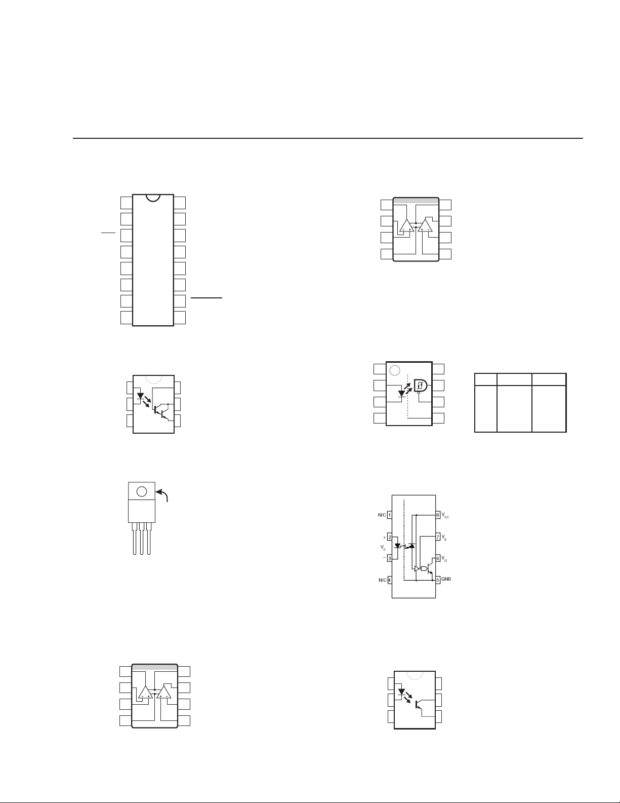
4. Parts
4.1 Semiconductor package descriptions and pinouts
Legend:
A = anode; B = base; C = collector; D = drain; G = gate; K = cathode; S = source
IC-000024-00
Controller, PWM, SG3525AN; 16-pin DIP
INV. INPUT
NON-INV. INPUT
SYNC
OSC. OUTPUT
DISCHARGE
SOFT START
1
2
3
4
C
5
T
R
6
T
7
8
V
16
RE F
V
15
CC
OUTPUT B
14
V
13
C
GROUND
12
OUTPUT A
11
SHUTDOWN
10
COMPENSATION
9
IC-000031-00
Opto isolator , 4N30; 6-pin DIP
1
2
3
6
5
4
IC-000047-30
Comparator , dual, LM393; 8-pin SMT
OUTPUT A
INVERTING
INPUT A
NON-INVERTING
INPUT A
GND
1
2
3
4
AB
V+
8
OUTPUT B
7
INVERTING
6
INPUT B
NON-INVERTING
5
INPUT B
IC-000049-00
Opto coupler , HCPL2200; 8-pin SMT
ANODE
CATHODE
NC
1
2
3
NC
4
SHIELD
V
8
CC
V
7
O
V
6
E
GND
5
TRUTH TABLE
(POSITIVE LOGIC)
LED ENABLE OUTPUT
ON
OFF
ON
OFF
H
H
L
L
Z
Z
H
L
IC-000042-00
Voltage regulator, +5V, MC7805CT ; 3-pin TO-220
GROUND
OUTPUT
GROUND
INPUT
IC-000046-30
Op amp, dual, TL072; 6-pin SMT
IC-000048-30
Op amp, dual, MC33078; 6-pin SMT
OUTPUT A
INVERTING
INPUT A
NON-INVERTING
INPUT A
V-
PowerLight 9.0
Parts lists
1
2
AB
3
4
PFC
, PowerLight 6.0
V+
8
OUTPUT B
7
INVERTING
6
INPUT B
NON-INVERTING
5
INPUT B
PFC
, PowerLight 6.0 II Service Manual 25
IC-000050-00
Opto coupler , 6N137; 8-pin DIP
IC-000051-00
Opto isolator , MOC8101; 6-pin DIP
1
2
3
NC
NC
6
5
4
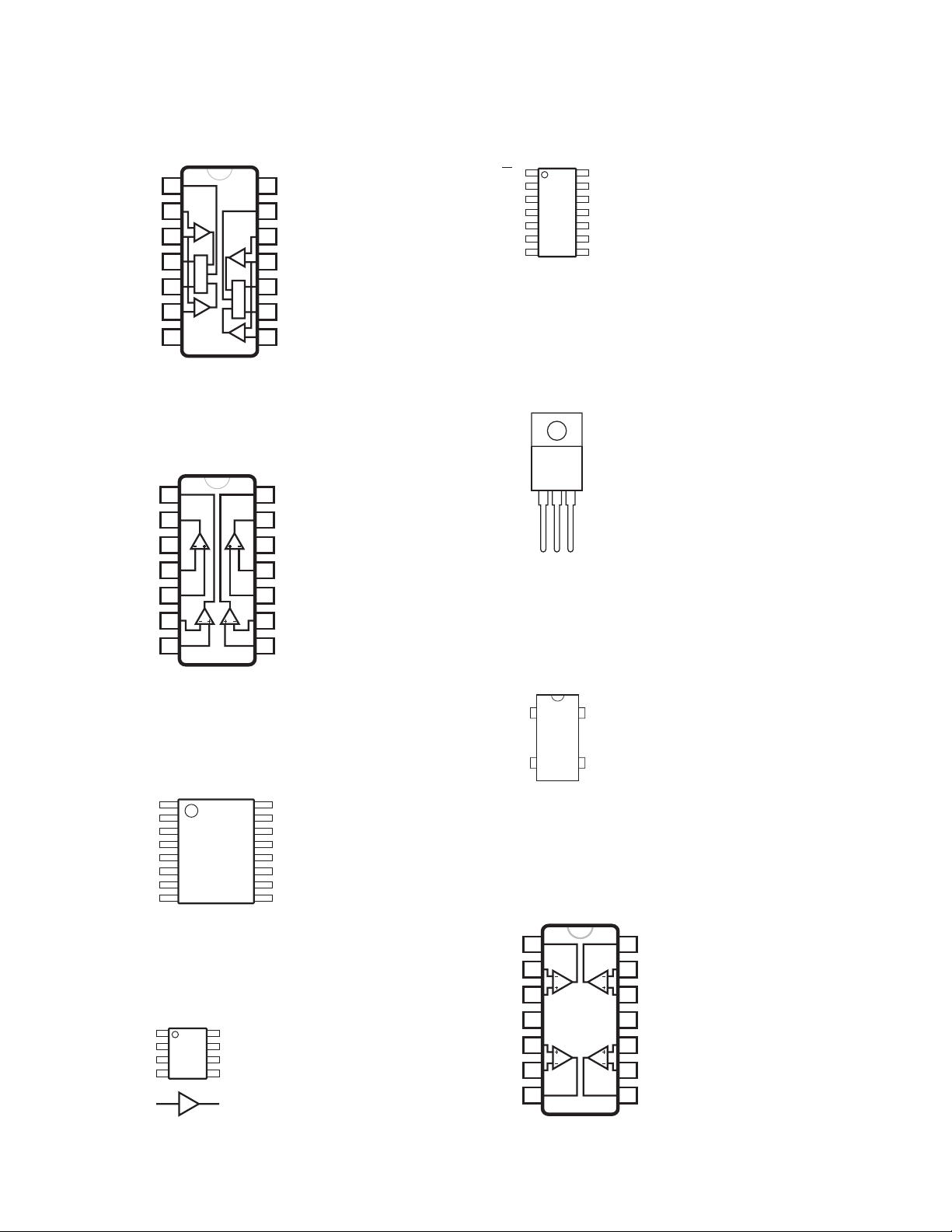
IC-000053-30
Timer, dual, LM556; 14-pin SMT
Comp.
Comp.
Flip-flop
14
13
12
11
10
9
8
DISCHARGE
THRESHOLD
CONTROL VOLTAGE
RESET
OUTPUT
TRIGGER
GROUND
1
2
Comp.
3
4
Flip-flop
5
6
Comp.
7
IC-000054-30
Comparator , quad, LM339AM; 14-pin SMT
V
CC
DISCHARGE
THRESHOLD
CONTROL VOLTAGE
RESET
OUTPUT
TRIGGER
IC-000057-30
Counter, ripple, 74HC4024, SMT; 14-pin SMT
1
MR
GND
CP
2
Q6
3
Q5
4
Q4
5
Q3
6
7
V
14
CC
NC
13
12
Q0
Q1
11
NC
10
Q2
9
NC
8
IC-000059-00
T op switch, TOP202; TO-220
IC-000235-00
T op switch, TOP224; TO-220
OUTPUT 2
OUTPUT 1
V+
INPUT 1-
INPUT 1+
INPUT 2-
INPUT 2+
1
2
1
3
4
5
2
6
7
14
OUTPUT 3
13
OUTPUT 4
4
12
GROUND
11
INPUT 4-
10
INPUT 4+
3
9
INPUT 3-
8
INPUT 3+
IC-000055-30
Regulator, power factor, UC3854B; 16-pin SMT
1
GND
PKLMT
CAO
ISENSE
MOUT
IAC
VAO
VRMS
2
3
4
5
6
7
8
16
15
14
13
12
11
10
9
GTDRV
VCC
CT
SS
RSET
VSENSE
ENA
VREF
IC-000056-30
Driver , MOSFET, TC4427; 8-pin SMT
1
NC
IN A
GND
IN B
2
3
4
2,4 7,5
8
7
6
5
NC
OUT A
V
DD
OUT B
DRAIN
SOURCE
CONTROL
IC-000060-00
Oscillator, clock, 6.000 MHZ; 4-pin DIP
GND
1
OE
7
14
V
DD
OUT
8
IC-000063-30
Op amp, quad, MC33074; 14-pin SMT
OUT 1
INV. 1
NON-INV. 1
V
NON-INV. 2
INV. 2
OUT 2
1
2
3
4
CC
5
6
7
14
OUT 4
13
INV. 4
12
NON-INV. 4
11
V
10
NON-INV. 3
9
INV. 3
8
OUT 3
EE
26 QSC Audio Products, Inc.
TD-000083-00
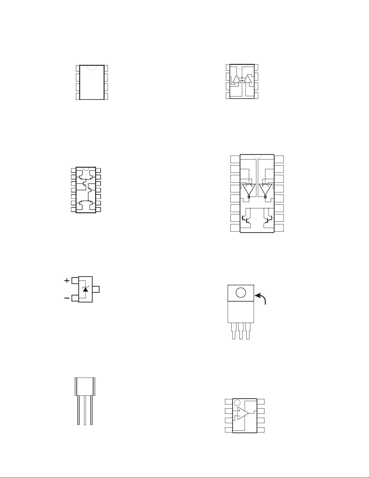
IC-000064-00
Driver , MOSFET, 4452BN; 8-pin DIP
GND
VS
1
IN
2
NC
3
4
VS
8
OUT
7
OUT
6
GND
5
IC-000067-30
Differential amplifier , dual, CA3054; 14-pin SMT
1
2
3
4
5
6
7
14
Q
1
Q
2
13
12
Q
3
Q
4
11
10
Q
5
NCSUBSTRATE
Q
6
9
8
IC-000072-OP
Op amp, dual, TL072; 8-pin DIP
OUTPUT A
INVERTING
INPUT A
NON-INVERTING
INPUT A
V-
1
2
3
4
AB
V+
8
OUTPUT B
7
INVERTING
6
INPUT B
NON-INVERTING
5
INPUT B
IC-000073-30
T ransconductance op amp, DUAL, LM13600M; 16-pin SMT
AMP BIAS INPUT A
DIODE BIAS A
NON-INVERTING
INPUT A
INVERTING INPUT A
OUTPUT A
BUFFER INPUT A
BUFFER OUTPUT A
1
2
3
4
AB
5
V-
6
7
8
AMP BIAS INPUT B
16
DIODE BIAS B
15
NON-INVERTING
14
INPUT B
INVERTING INPUT B
13
OUTPUT B
12
V+
11
BUFFER INPUT B
10
BUFFER OUTPUT B
9
IC-000070-30
Voltage reference, +2.5V, LM4040DIM3X-2.5; 3-pin SOT-30 (SMT)
1
3
2
IC-000071-00
Sensor, temperature, LM35DZ; TO-92
+VSV
GND
OUT
IC-000085-00
Voltage regulator, +12V, LM2937ET -12, low drop out; TO-220
GROUND
OUTPUT
GROUND
INPUT
IC-000133-30
Comparator , single, LM311; 8-pin SMT
GROUND 1
NON-INVERTING
INPUT
INVERTING
INPUT
1
2
3
4
V-
8
7
6
5
V+
OUTPUT
BALANCE/
STROBE
BALANCE
PowerLight 9.0
Parts lists
PFC
, PowerLight 6.0
PFC
, PowerLight 6.0 II Service Manual 27
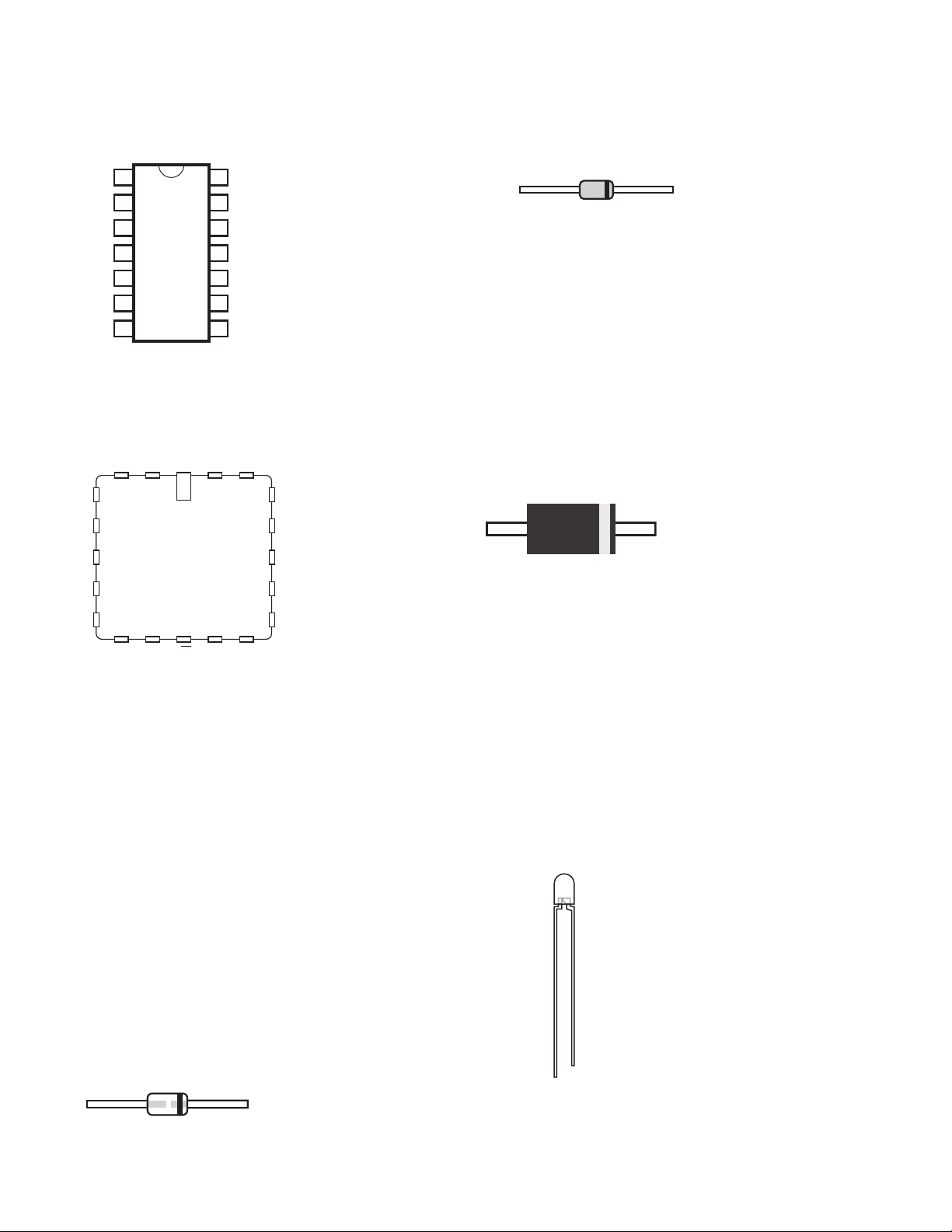
IC-000134-00
Driver , MOSFET, IR2110; 14-pin DIP
QD-000024-QD
Diode Zener, 6.2V, , 0.25W, DZ901116G, DO-35
LO
COM
V
HO
1
2
3
CC
4
5
V
S
6
V
B
7
14
13
V
SS
12
LIN
11
SD
10
HIN
9
V
DD
8
PD-000036-30
Power supply signal management, GAL16V8, PL9.0
This device must be programmed by QSC before installation.
I I I/CLK Vcc I/O/Q
I
4
I
6
I
I
8
I
232019
I GND I/OE
I/O/Q I/O/Q
18
16
14
13119
I/O/Q
I/O/Q
I/O/Q
I/O/Q
I/O/Q
PFC
and PL6.0
AK
PFC
QD-000042-00
Diode rectifier ultrafast, 400V, 3A, MUR440, DO-201AD, 50 ns
AK
QD-000052-00
LED green, T -1, diffused
QD-000022-QD
Diode Zener, 18V, 1W, 1N4746A, DO-41
QD-000053-00
LED yellow, T-1
QD-000023-QD
Diode Zener, 180V, , 1.5W, 1N5955A, DO-41
QD-000054-00
LED red, T -1
QD-000047-00
Diode Zener, 200V, , 1.5W, 1N5956B, DO-41
QD-000080-20
Diode Zener, 11V, 1W, 1N4741A, DO-41
QD-000159-20
Diode Zener, 47V, 1W, 1N4756, DO-41
QD-000159-20
Diode Zener, 47V, , 1W, 1N4756, DO-41
AK
28 QSC Audio Products, Inc.
ANODE
CATHODE
TD-000083-00
 Loading...