


KLA AF12
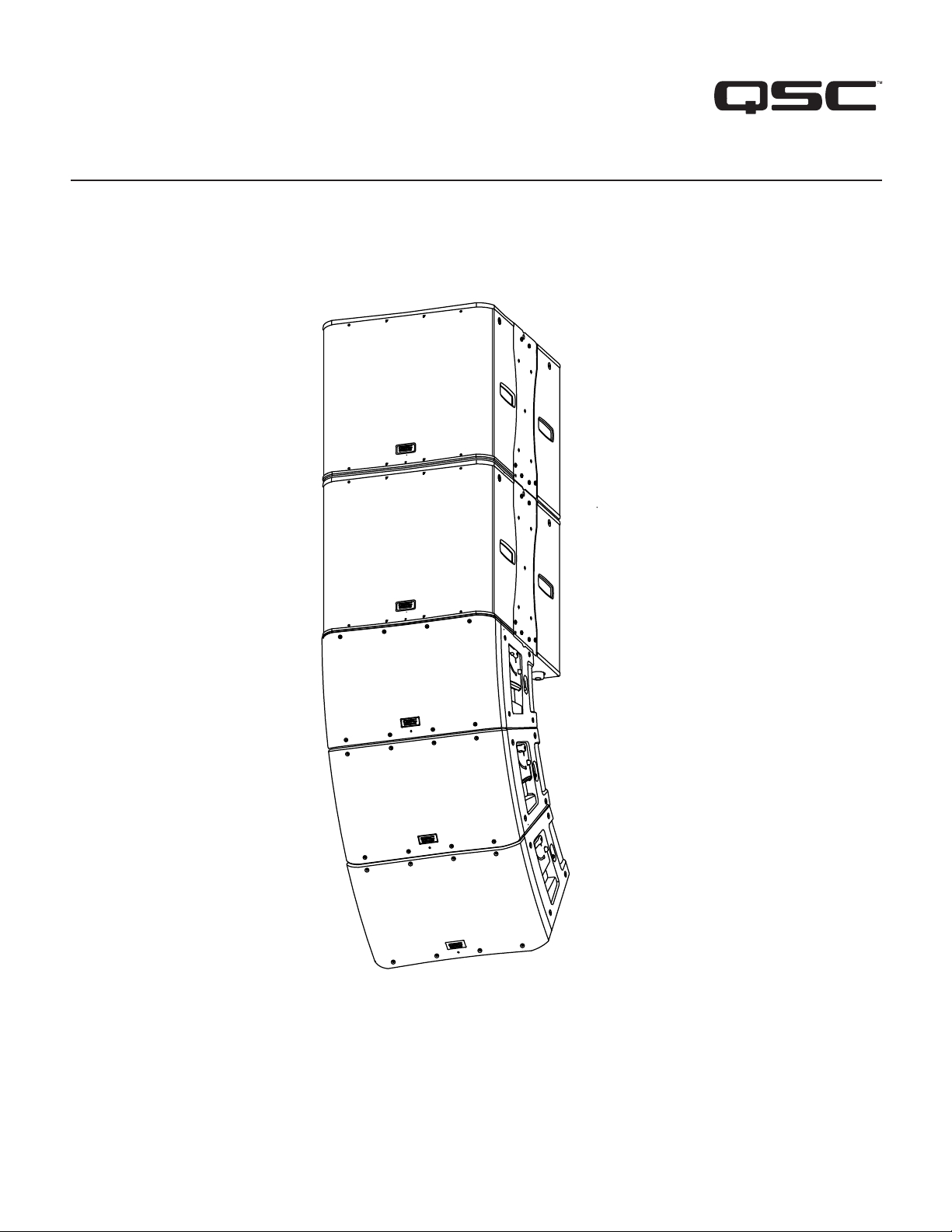
KLA12 – 12" 2-way Loudspeaker
KLA181 – 18" Subwoofer
KLA AF12 – Array Frame
KLA Series
User Manual
TD-000319-01-E
*TD-000319-01-E*
2
TD-000319-01-E
EXPLANATION OF SYMBOLS
The term “WARNING!” indicates instructions regarding personal safety. If the instructions are not followed the result may be bodily injury or death.
The term “CAUTION!” indicates instructions regarding possible damage to physical equipment. If these instructions are not followed, it may result in
damage to the equipment that may not be covered under the warranty.
The term “IMPORTANT!” indicates instructions or information that are vital to the successful completion of the procedure.
The term "NOTE" is used to indicate additional useful information.
The intent of the lightning fl ash with arrowhead symbol in a triangle is to alert the user to the presence of un-insulated "dangerous"
voltage within the product's enclosure that may be of suffi cient magnitude to constitute a risk of electric shock to humans.
The intent of the exclamation point within an equilateral triangle is to alert the user to the presence of important safety, and operating
and maintenance instructions in this manual.
IMPORTANT SAFETY INSTRUCTIONS
WARNING!:
TO PREVENT FIRE OR ELECTRIC SHOCK, DO NOT EXPOSE THIS EQUIPMENT TO RAIN OR MOISTURE.
WARNING!:
While it is possible for one person to lift a KLA12 loudspeaker, it is important to use proper lifting techniques.
Suggested reading: OSHA Technical Manual on Back Disorders and Injuries
(http://www.osha.gov/dts/osta/otm/otm_vii/otm_vii_1.html#app_vii:1_2).
1. Keep these instructions.
2. Heed all warnings.
3. Follow all instructions.
4. Do not use this apparatus near water.
5. Clean only with a dry cloth.
6. Do not block any ventilation opening. Install in accordance with the manufacturer's instructions.
7. Do not install near any heat sources such as radiators, heat registers, stoves, or other apparatus (including amplifi ers) that produce heat.
8. Do not defeat the safety purpose of the polarized or grounding-type plug. A polarized plug has two blades with one wider than the other. A
grounding type plug has two blades and a third grounding prong. The wide blade or the third prong are provided for your safety. If the provided
plug does not fi t into your outlet, consult an electrician for replacement of the obsolete outlet.
9. Protect the power cord from being walked on or pinched particularly at plugs, convenience receptacles, and the point where they exit from
the apparatus.
10. Only use attachments/accessories specifi ed by the manufacturer.
11. Unplug this apparatus during lightning storms or when unused for long periods of time.
12. Refer all servicing to qualifi ed service personnel. Servicing is required when the apparatus has been damaged in any way, such as power-supply
cord or plug is damaged, liquid has been spilled or objects have fallen into the apparatus, the apparatus has been exposed to rain or moisture,
does not operate normally, or has been dropped.
13. The appliance coupler, or the AC Mains plug, is the AC mains disconnect device and shall remain readily operable after installation. On units
equipped with powerCon® connectors, the AC Mains disconnect device is the AC Mains plug only; do not use the appliance coupler.
14. Adhere to all applicable, local codes.
15. Consult a licensed, professional engineer when any doubt or questions arise regarding a physical equipment installation.

3
TD-000319-01-E
FCC Statement
NOTE:
This equipment has been tested and found to comply with the limits for a Class B digital device, pursuant to Part 15 of the
FCC Rules.
These limits are designed to provide reasonable protection against harmful interference in a residential installation. This equipment generates, uses
and can radiate radio frequency energy and, if not installed and used in accordance with the instructions, may cause harmful interference to radio
communications. However, there is no guarantee that interference will not occur in a particular installation. If this equipment does cause harmful
interference to radio or television reception, which can be determined by turning the equipment off and on, the user is encouraged to try to correct
the interference by one or more of the following measures:
• Reorient or relocate the receiving antenna.
• Increase the separation between the equipment and receiver.
• Connect the equipment into an outlet on a circuit different from that to which the receiver is connected.
• Consult the dealer or an experienced radio/TV technician for help.
Warranty
For a copy of the QSC Limited Warranty, visit the QSC Audio Products website at www.qsc.com.

4
TD-000319-01-E
Suspending the KLA Series Loudspeakers
WARNING!:
Read and follow these instructions carefully. If the loudspeakers are not suspended properly, they could fall,
causing personal injury and damage to the equipment.
Rules for Suspension
• Consult a professional mechanical or structural engineer, licensed in the jurisdiction of the sound system installation, to review, verify, and approve
all attachments to the building or structure.
• Employ the services of a certifi ed, professional rigger for hoisting, positioning, and attaching the equipment to the supporting structure.
• Correct use of all suspension hardware and components is imperative in sound system suspension and deployment.
• Always calculate suspended loads before lifting to make sure suspension components and hardware are used within their respective load limits.
• Consult local codes and regulations to fully understand the requirements for suspended loads in the venue in which you will suspend
the equipment.
• Use only the KLA AF12 Array Frame or the M10 installation points for suspending the array.
• Be absolutely certain of the integrity of any structural member intended to support suspended loads. Hidden structural members can have hidden
structural weakness.
• Never assume anything! Owner or third-party supplied suspension attachment points may not be adequate for suspending the loads.
• Before lifting, always inspect all components (enclosures, suspension brackets, pins, frames, bolts, nuts, slings, shackles, etc.) for cracks, wear,
deformation, corrosion, missing, loose, or damaged parts that could reduce the strength of the assembly. Discard any worn, defective, or suspect
parts and replace them with new appropriately load-rated parts.
Shock Loading
When a load is either moved or stopped, its static weight is magnifi ed. Sudden movements can magnify the static weight several times. This
magnifi cation of static weight is called "shock loading". Shock loading poses a danger to equipment and workers. The effects of shock loading can be
instantaneous, or may remain undetected unless the equipment is visually damaged. Proper preparation for shock loading requires careful planning
and knowledge of equipment, suspension, and lifting practices.
Shock loading of equipment and structures is usually confi ned to lifting and installation, but natural forces (winds, earthquakes, and so on) can impose
shock loads several times the static load. Because of this, structures and suspension equipment must be capable of supporting several times the
weight of the suspended equipment.
KLA Maximum Suspended Load
The KLA components are engineered for a 10:1 design factor.
Use the KLA AF12 Array Frame or the M10 Integrated Suspension points to suspend one KLA Array consisting of one of the following three array
confi guration options. The maximum number of KLA12 Loudspeakers in any array, with or without KLA181 Loudspeakers, is fi ve.
Suspended Loudspeakers per Array
Array Confi guration Option A B C
Maximum Number of KLA181 Loudspeakers 2 3 4
Maximum Number of KLA12 Loudspeakers 5 3 0
— Table 1 —
Individual Component Weights
KLA12 KLA181 KLA AF12
55 lbs. (25 kg) 104 lbs. (47.2 kg) 23 lbs. (10.4 kg)
— Table 2 —

5
TD-000319-01-E
Introduction
The KLA Series brings the power and sophistication of a line-array system into an easy-to-use product signifi cantly redefi ning the line-array-product
category. With its simple Lift, Click and Play approach, KLA deploys in a fraction of the time required by comparable line-array products. This fi xed
arcuate, active line-array system is ideal for a wide range of portable and permanently installed applications ranging from live entertainment to houses
of worship or other venues where a line-array system is desired.
The KLA Series is comprised of two models: the KLA12 12-inch, 2-way loudspeaker and the KLA181 18-inch subwoofer. The KLA12 features a highly
effi cient 500 W x 500 W power-amp module in a rugged, lightweight ABS enclosure that can be used in multiple confi gurations using QSC's unique
SOLO™ (Single-Operator Logistics) Rigging System and/or Tilt-Direct™ 35 mm pole socket. The KLA181 offers the same highly effi cient power-amp
module in a 1,000 W confi guration in a birch plywood enclosure. KLA Series loudspeaker models incorporate:
QSC’s DEEP™ DSP algorithm, providing extended bass response by actively managing potentially damaging low-frequency transients,
GuardRail™ circuitry protection that prevents the amplifi er module from unnatural and destructive clipping,
Intrinsic Correction™ (KLA12) to correct for inherent characteristics of the loudspeakers, waveguide, and enclosures,
Ar-Q™ to make equalization adjustments based on the number of KLA12s in the array,
Auto Standby mode that automatically engages after fi ve minutes of inactivity, but upon resumption of audio signal, the power module on the KLA
awakens instantly for immediate output.
Remote Gain control capability in an installed application using a single potentiometer wired to a Euro-style connector.
Balanced, line-level XLR input, in parallel with an XLR output, for distributing the audio signal to multiple loudspeakers.
powerCON® AC In and AC Out connectors for powering up to fi ve loudspeakers on a single 15 amp/120 V (8 amp/240 V) electrical circuit.
Other features include LED indicators for Signal and Limit, and discrete LED indicators for Power/Standby status.
Unpacking
KLA12 Package Contents
1. Quick-Start Guide
2. Warning Information Sheet
3. KLA12 Speaker Assembly
4. AC powerCON® Power Cord (CEE 7/7), 3.6 Meter
5. AC powerCON® Power Cord (NEMA 5-15 - USA style), 12 Foot
6. XLR Audio Loop-thru Cable, 2 Foot
7. powerCON® Loop-thru Power Cord, 2 Foot
8. Euro-style Connector Plug, 3-pin
KLA181 Package Contents
1. Quick-Start Guide
2. Warning Information Sheet
3. KLA181 Subwoofer Assembly
4. AC powerCON® Power Cord (CEE 7/7), 3.6 Meter
5. AC powerCON® Power Cord (NEMA 5-15 - USA style), 12 Foot
6. XLR Audio Loop-thru Cable, 3 Foot
7. powerCON® Loop-thru Power Cord, 3 Foot
8. Hex Key, 6 mm
9. Euro-style Connector Plug, 3-pin
6
TD-000319-01-E
Features
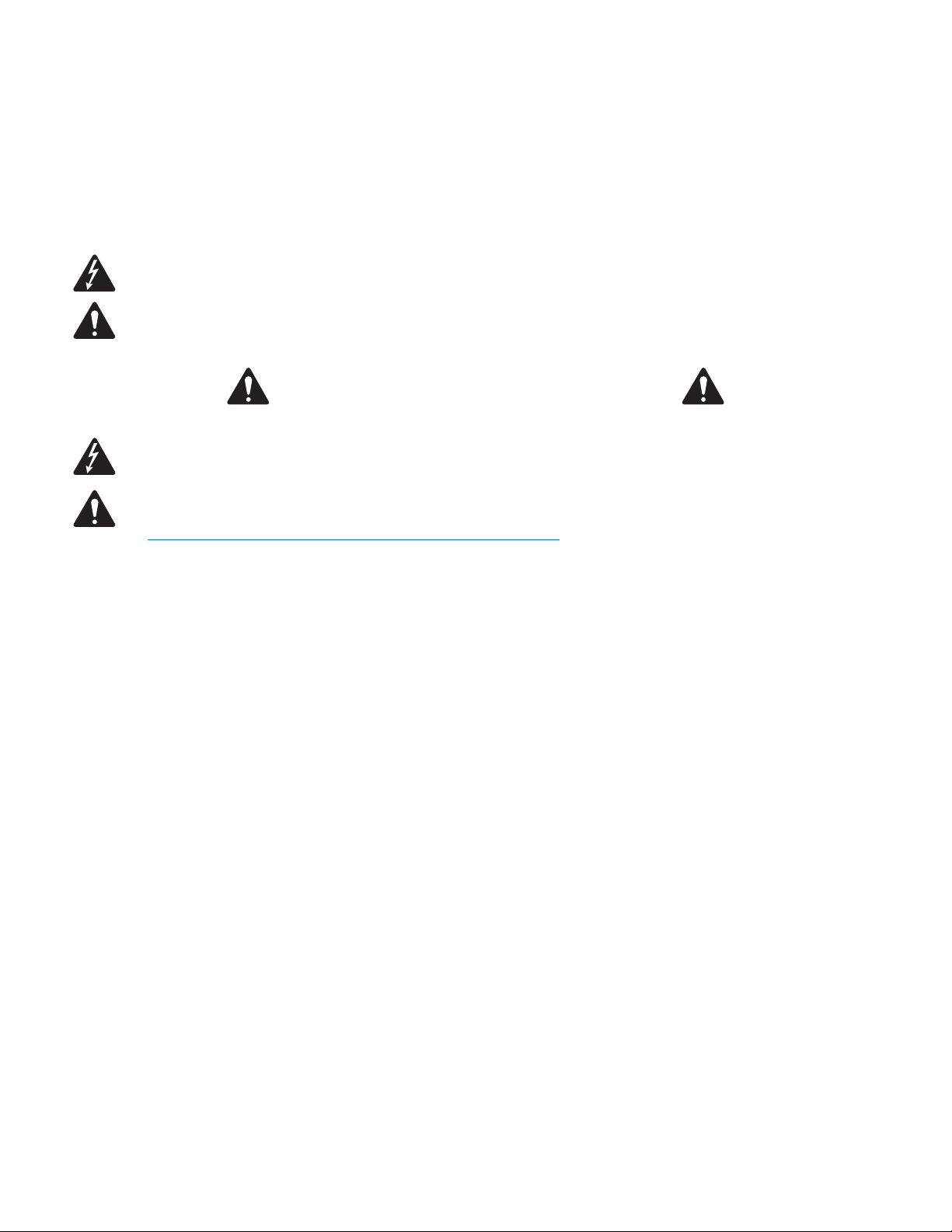
KLA12
— Figure 1 —
1
2
3
4
9
9
5
6
7
8
8
8
8
6
6
4
4
4
8
1. ABS enclosure
2. Steel grille
3. Front power LED
4. Handles
5. Power module
6. M10 installation points (3)
7. Tilt-Direct™ dual angle (0° or -9°) pole socket
8. Slip-resistant feet
9. Side Rigging Plates
7
TD-000319-01-E
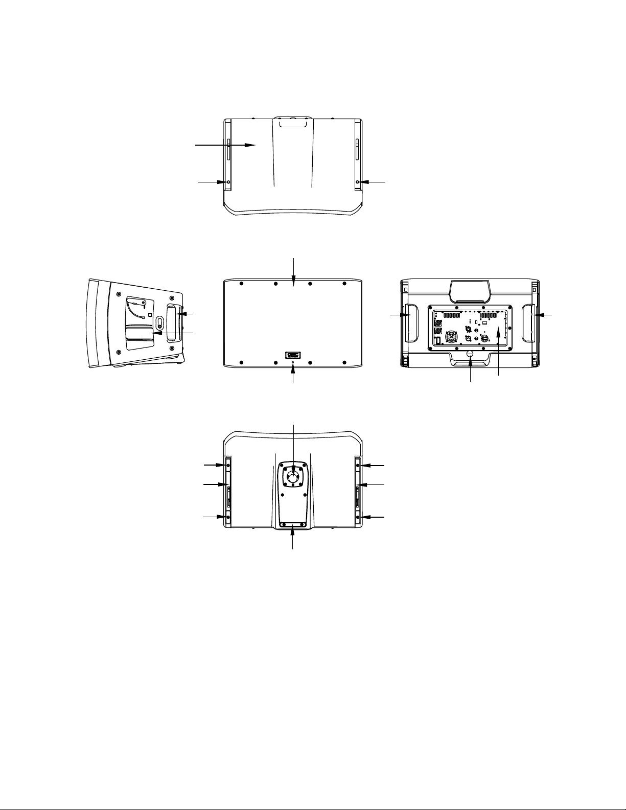
KLA181
— Figure 2 —
1
2
3
4
5
6
7
9
6
6
6
7
7
10
10
10
10
4
7
8
1. Baltic Birch enclosure
2. Steel grille
3. Front power LED
4. Handles
5. Power module
6. M10 installation points (4)
7. Slip-resistant feet
8. M20 threaded, 35 mm pole mount (black model only)
9. Side rigging plates
10. Feet alignment receptacles
8
TD-000319-01-E
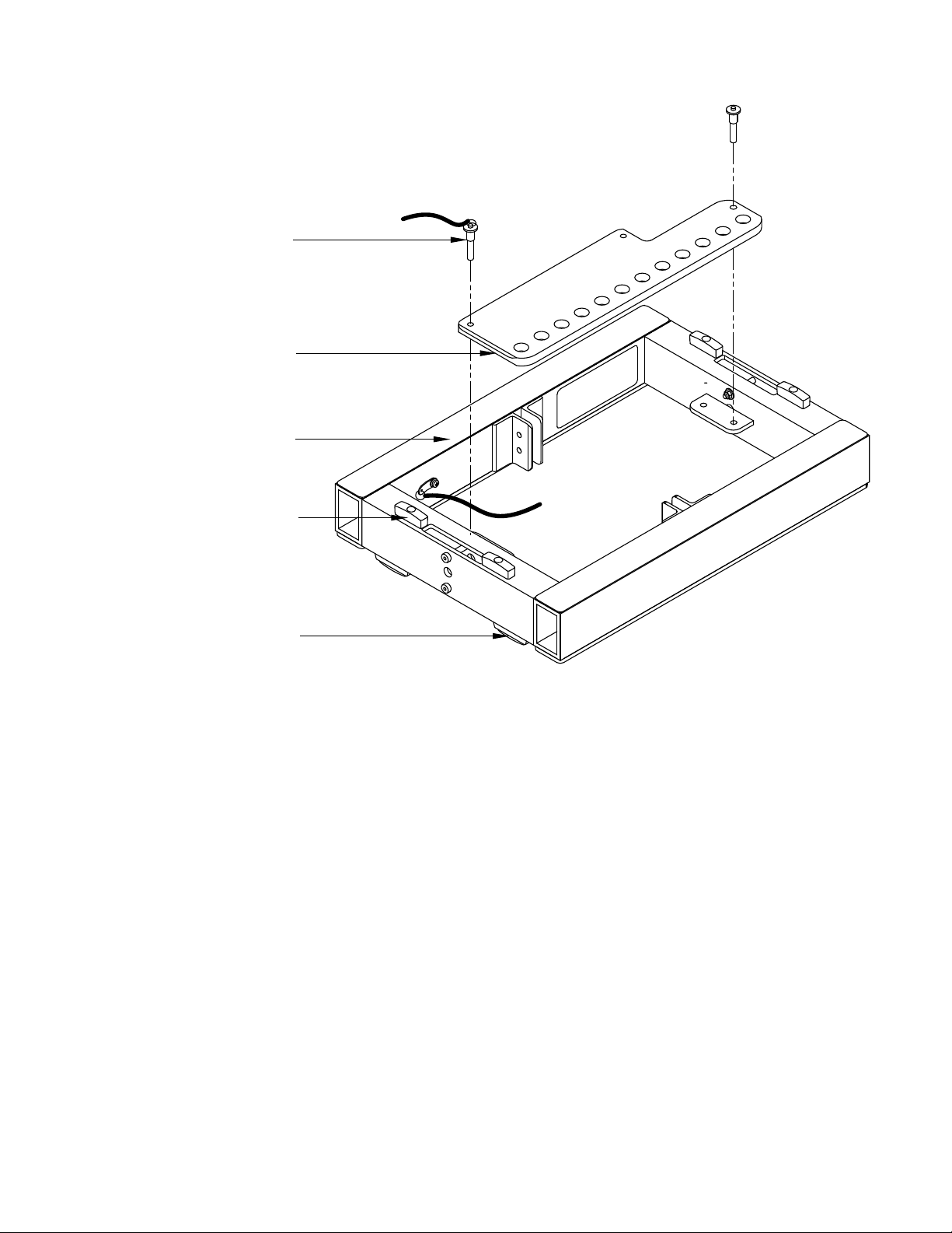
KLA AF12
(Shown as shipped)
1. Rigging pins and lanyard (2)
2. Array extension beam
3. Array frame
4. Feet for KLA181 application
5. Feet for KLA12 application
— Figure 3 —
1
2
3
4
5
 Loading...