


GXD Amplifier
Quick Start Guide
EXPLANATION OF TERMS AND SYMBOLS
The term “WARNING!” indicates instructions regarding personal safety. If the instructions are not followed the result may be bodily injury or death.
The term “CAUTION!” indicates instructions regarding possible damage to physical equipment. If these instructions are not followed, it may result in damage to the equipment that may not be covered under the warranty.
The term “IMPORTANT!” indicates instructions or information that are vital to the successful completion of the procedure.
The term "NOTE" is used to indicate additional useful information.
The intent of the lightning flash with arrowhead symbol in a triangle is to alert the user to the presence of un-insulated "dangerous" voltage within the product's enclosure that may be of sufficient magnitude to constitute a risk of electric shock to humans.
The intent of the exclamation point within an equilateral triangle is to alert the user to the presence of important safety, and operating and maintenance instructions in this manual.
NOTE: This Quick Start Guide is based on the basic configuration as the amplifier comes from the factory. For detailed instructions for custom configurations refer to the GXD User Guide.
Rack-Mount the Amplifier
1. Secure the amplifier in the rack with eight screws (not supplied), four in front, four in back.
— Figure 1 —
TD-000449-00-A
*TD-000449-00*

Connections
Inputs (Channels 1 & 2)
Input Impedance: 40 kΩ Balanced, 20 kΩ Unbalanced (Figure 2) See Table 1 for wiring
|
POS |
NEG |
GROUND |
|
|
XLR |
2 |
3 |
1 |
|
|
1/4 |
TIP |
RING |
SLEEVE |
|
|
|
— Table 1 — |
1 |
2 |
3 |
|
|
|
|
|
||
1. XLR female |
|
|
|
— Figure 2 — |
|
2.¼" female TRS Phone Jack
3.USB Standard B connector - Used for updating the amplifier firmware.
OUTPUTS TO SPEAKERS
|
CK |
C |
|
|
LO K |
||
|
LO |
|
|
CH A |
|
||
1+ |
1- |
CH B |
|
CH B |
|||
1+ 1- |
|||
2+ |
2- |
||
|
|||
— Figure 3 —
Outputs (Channels A & B)
4Ω or 8Ω impedance (Figure 3)
1. NL4 – Do not combine the audio outputs in any way. Do not connect the audio outputs to ground.
AC Power
A. Connect the IEC power cord to the AC receptacle on the rear of the amplifier. (Figure 4)
Controls
See Figure 5.
1.Channel A clip indicator
2.Channel A signal presence indicator
3.Power Switch/LED on/off
4.Adjust Channel A gain
5.Home – go to Home screen / view Preset screen
6.Enter – select highlighted item and/or confirm parameter change
7.Exit – return to previous screen and/or undo parameter changel
8.Adjust Channel B gain, select and adjust controls
9.Channel B signal presence indicator
10.Channel B clip indicator
|
|
|
|
|
— Figure 4 — |
|
1 |
A |
SIGCLIP |
|
|
CLIPSIG |
10 |
2 |
+P1: ST SAT FULL RANGE |
B |
||||
|
|
A |
|
B |
9 |
|
|
|
|
dB |
|
||
|
|
|
-100 |
10.0 |
|
|
PROCESSING |
GAIN |
STATUS: OK |
|
GAIN/DSP CONTROL |
||
AMPLIFIER |
|
|||||
|
|
|
|
|
||
|
|
|
HOME |
ENTER |
EXIT |
|
3 |
|
4 |
5 |
6 |
7 |
8 |
— Figure 5 —
GXD Amplifier Signal Flow
|
Front Panel |
|
|
|
|
|
|
|
|
|
|
|
|
|
|
|
|
|
|
|
|
|
|
|
|
|
|
|
|
|
|
|
|
|
Clip |
|
|
|
|
|
|
|
|
|
|
|
|
|
|
|
|
|
|
|
|
|
|
|
|
|
|
|
|||
|
LEDs |
|
LED |
|
|
|
|
|
|
|
|
|
Digital Signal Processing |
|
|
|
|
|
|
|
|
|
|
|
||||||||
|
|
|
|
|
|
|
|
|
|
|
|
|
|
|
|
|
|
|
|
|
|
|
|
|
|
|||||||
|
|
|
|
|
|
|
|
|
|
|
|
|
|
|
|
|
|
|
|
|
|
|
|
|
|
|
|
|
|
|
|
|
|
|
|
|
|
|
|
|
|
|
|
|
|
|
|
|
|
|
|
|
|
|
|
|
|
|
|
|
|
|
|
|
|
|
|
|
|
A/D |
|
|
Signal |
|
|
|
|
|
High-pass |
|
|
|
Low-pass |
|
4-band |
|
|
|
|
|
|
|
D/A |
|
|
|
||
|
Sensitivity |
|
|
|
|
|
|
Gain |
|
|
Polarity |
|
|
Delay |
|
Limiter |
Meter |
|
|
A |
|
|||||||||||
|
|
Converter |
|
|
Presence |
|
|
|
|
Filter |
|
|
Filter |
|
PEQ |
|
|
|
|
Converter |
|
|||||||||||
|
|
|
|
|
|
|
|
|
|
|
|
|
|
|
|
|
|
|
|
|
|
|
|
|||||||||
|
|
|
|
|
|
|
|
|
|
|
|
|
|
|
|
|
|
|
|
|
|
|
|
|
|
|
|
|
|
|
|
|
|
Switched |
|
|
|
|
|
|
Front |
|
Routing |
|
Front |
|
|
|
|
|
|
|
|
|
|
|
|
Shown on |
|
|
|
|
|
||
|
|
|
|
|
|
|
|
|
|
|
|
|
|
|
|
|
|
|
|
|
|
|
|
|
|
|||||||
|
|
|
|
|
|
|
Panel |
|
|
Panel |
|
|
Crossover |
|
|
|
|
|
|
|
|
|
|
|
|
|
||||||
|
in DSP |
|
|
|
|
|
|
|
Matrix |
|
|
|
|
|
|
|
|
|
|
|
LCD |
|
|
|
|
|
||||||
|
|
|
|
|
|
|
LEDs |
|
|
Knobs |
|
|
|
|
|
|
|
|
|
|
|
|
|
|
|
|
|
|||||
|
|
|
|
|
|
|
|
|
|
|
|
|
|
|
|
|
|
|
|
|
|
|
|
|
|
|
|
|
|
|
||
|
|
|
|
|
|
|
|
|
|
|
|
|
|
|
|
|
|
|
|
|
|
|
|
|
|
|
|
|
|
|
||
|
Sensitivity |
|
|
A/D |
|
|
Signal |
|
|
|
|
|
High-pass |
|
|
|
Low-pass |
|
4-band |
|
|
|
|
|
|
|
D/A |
|
|
|
||
|
|
|
|
|
|
|
Gain |
|
|
Polarity |
|
|
Delay |
|
Limiter |
Meter |
|
|
B |
|
||||||||||||
|
|
Converter |
|
|
Presence |
|
|
|
|
Filter |
|
|
Filter |
|
PEQ |
|
|
|
|
Converter |
|
|||||||||||
|
|
|
|
|
|
|
|
|
|
|
|
|
|
|
|
|
|
|
|
|
|
|
|
|||||||||
|
|
|
|
|
|
|
|
|
|
|
|
|
|
|
|
|
|
|
|
|
|
|
|
|
|
|
|
|
|
|
|
|
|
Front Panel |
|
|
|
|
|
|
|
|
Controlled |
|
|
|
|
|
|
|
|
|
|
|
|
|
|
|
|
|
|
|
|
||
|
|
Clip |
|
|
|
|
|
|
|
|
|
|
|
|
|
|
|
|
|
|
|
|
|
|
|
|
|
|||||
|
|
|
|
|
|
|
by Preset |
|
|
|
|
|
|
|
|
|
|
|
|
|
|
|
|
|
|
|
|
|||||
|
LEDs |
|
LED |
|
|
|
|
|
Selection |
|
|
|
|
|
|
|
|
|
|
|
|
|
|
|
|
|
|
|
|
|||
|
|
|
|
|
|
|
|
|
|
|
|
|
|
|
|
|
|
|
|
|
|
|
|
|
|
|
|
|
|
|
|
|
|
|
|
|
|
|
|
|
|
|
|
|
|
|
|
|
|
|
|
|
|
|
|
|
|
|
|
|
|
|
|
|
|
— Figure 6 —
TD-000449-00-A |
2 |
Setup and Operation
Menu Tree
Preset |
Stereo DSP |
Utilities |
|||
|
Preset Recall |
|
Sensitivity |
|
Status |
|
|
|
|||
|
Preset Save |
|
Crossover |
|
Contrast |
|
|
|
|||
|
Preset Save As |
|
EQ |
|
Timeout |
|
|
|
|||
|
|
|
Delay |
|
Lockout |
|
|
|
|
||
|
|
|
Limiter |
|
Reset |
|
|
|
|
||
|
|
— Figure 7 — |
|
|
|
Key
 B
B
Turn |
Knob B (or A) |
Select / Press |
Adjust |
Home Screen
See Figure 8
From any screen  HOME
HOME
1.Currently active Preset (location and name)
2.Limit and Clip indicators
3.Output channel letter A and B
4.Output meter A and B (visual)
5.Output Gain (digital) Range = -100 to +10 dB
6.Amplifier Status
1 |
+P1: ST SAT FULL RANGE |
||
2 |
A LIMIT |
|
CLIP B |
3 |
dB |
||
4 |
-100 |
|
10.0 |
5 |
|
||
6 |
STATUS: OK |
|
|
|
— Figure 8 — |
||
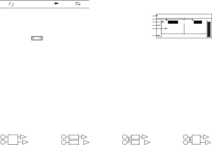
Configurations
There are four basic types of configuration:
•2-channels in, stereo DSP, 2-channels out (P1 through P7) Figure 31
•2-channels in, separate DSP, 2-channels out (P8 through P10) Figure 32
•1or 2-channel in, separate DSP, 2-channels out (P11 through P18) Figure 33
•1 or 2-channel in, stereo DSP, 2-channels out (P19 and P20) Figure 34
1 |
ST |
A |
|
1 |
DSP |
A |
1 |
DSP |
A |
1 |
ST |
A |
|
|
|
|
|
|
|
|
|
|
|
||
2 |
DSP |
|
B |
2 |
DSP |
B |
2 |
DSP |
B |
2 |
DSP |
B |
|
— Figure 9 — |
|
|
— Figure 10 — |
|
— Figure 11 — |
|
— Figure 12 — |
||||
The configurations are selected using the Presets. Refer to the GXD User Manual for details on all 20 available Configurations.
TD-000449-00-A |
3 |
 Loading...