


7
6 |
DVD /CD |
7 |
FM/AM |
– DOWN VOLUME |
UP+ |
STANDBY/ON |
0 OPEN/CLOSE
XV-DV515
DVD/CD RECEIVER
XV-DV515
XV-DV313
THIS MANUAL IS APPLICABLE TO THE FOLLOWING MODEL(S) AND TYPE(S).
ORDER NO.
RRV2772
Model |
Types |
|
|
|
|
Power Requirement |
Region No. |
Remarks |
||
|
|
|
|
|
|
|
|
|
|
|
XV-DV515 |
MYXJ |
AC220-230V |
2 |
|
||||||
|
|
|
|
|
|
|
|
|
|
|
XV-DV515 |
NVXJ |
AC230V |
2 |
|
||||||
|
|
|
|
|
|
|
|
|
|
|
XV-DV313 |
MYXJN |
AC220V-230V |
2 |
|
||||||
|
|
|
|
|
|
|
|
|
|
|
XV-DV313 |
NVXJN |
AC230V |
2 |
|
||||||
|
|
|
|
|
|
|
|
|
|
|
|
|
|
|
|
|
|
|
|
|
|
|
|
|
|
|
|
|
|
|
|
|
|
|
|
|
|
|
|
|
|
|
|
|
|
|
|
|
|
|
|
|
|
|
|
|
|
|
|
|
|
|
|
|
|
For details, refer to "Important symbols for good services" on the next page.
PIONEER CORPORATION 4-1, Meguro 1-chome, Meguro-ku, Tokyo 153-8654, Japan
PIONEER ELECTRONICS (USA) INC. P.O. Box 1760, Long Beach, CA 90801-1760, U.S.A.
PIONEER EUROPE NV Haven 1087, Keetberglaan 1, 9120 Melsele, Belgium
PIONEER ELECTRONICS ASIACENTRE PTE. LTD. 253 Alexandra Road, #04-01, Singapore 159936
 PIONEER CORPORATION 2003
T – ZZV MAY. 2003 Printed in Japan
|
1 |
|
2 |
|
3 |
|
4 |
|
|
|
|
|
|
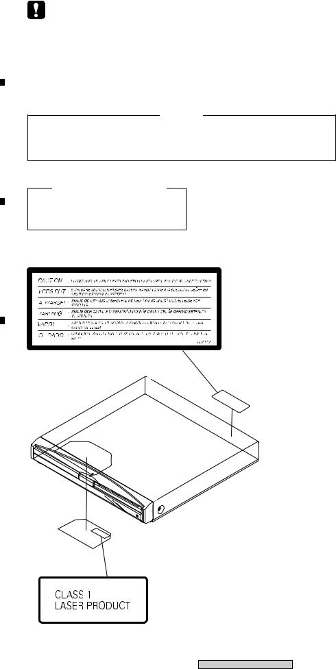
SAFETY INFORMATION
A
This service manual is intended for qualified service technicians ; it is not meant for the casual do- it-yourselfer. Qualified technicians have the necessary test equipment and tools, and have been trained to properly and safely repair complex products such as those covered by this manual.Improperly performed repairs can adversely affect the safety and reliability of the product and may void the warranty. If you are not qualified to perform the repair of this product properly and safely, you should not risk trying to do so and refer the repair to a qualified service technician.
WARNING !
THE AEL (ACCESSIBLE EMISSION LEVEL) OF THE LASER POWER OUTPUT IS LESS THAN CLASS 1
BUT THE LASER COMPONENT IS CAPABLE OF EMITTING RADIATION EXCEEDING THE LIMIT FOR
BCLASS 1.
A SPECIALLY INSTRUCTED PERSON SHOULD DO SERVICING OPERATION OF THE APPARATUS.
LASER DIODE CHARACTERISTICS
FOR DVD : MAXIMUM OUTPUT POWER : 5 mW
WAVELENGTH : 650 nm
FOR CD : MAXIMUM OUTPUT POWER : 7 mW
WAVELENGTH : 780 nm
C |
LABEL CHECK |
|
VRW1872
D
|
|
|
|
|
|
Additional Laser Caution |
|
|
|
|
|
|
|
|
|
|
|
|
|
|
1. Laser Interlock Mechanism |
||
|
|
|
|
|
• Loading switch (S101 on the LOAB Assy) is used for interlock |
||
|
|
|
|
|
|||
|
|
|
|
|
mechanism of the laser. |
||
|
|
|
|
|
When this switch turned ON in SW2 (CLOSE) side (OPEN signal is |
||
|
|
|
|
|
0V and CLOSE signal is 3.5V), a laser becomes the status which can |
||
|
|
|
|
|
completely oscillation. |
||
|
|
|
|
|
Furthermore, the laser completely oscillates in the disc judgment and |
||
|
|
|
|
|
disc playback. |
||
E |
|
|
When player is power ON state and laser diode is not completely |
||||
|
|
oscillating, 780nm laser diode is always oscillating by half power. |
|||||
|
|
|
|
|
|||
|
|
|
|
|
• Laser diode is driving with Q201 (650nm LD) and Q211 (780nm LD) |
||
|
|
|
|
|
on the DVDM Assy. |
||
|
|
|
|
|
Therefore, when short-circuit between the emitter and collector of these |
||
|
|
|
|
|
transistors or the base voltage is supplied for transistors turn on, the |
||
|
|
|
Name Label |
laser oscillates. (failure mode) |
|||
|
|
|
• In the test mode , there is the mode that the laser oscillates except |
||||
|
|
|
|
|
|||
|
|
|
|
|
for the disc judgment and playback. LD ON mode in the test mode |
||
|
|
|
|
|
|||
|
|
|
|
|
oscillates with the laser forcibly. |
||
|
|
|
|
|
The interlock mechanism mentioned above becomes invalid in this |
||
|
|
|
|
|
mode. |
||
|
|
|
|
|
2. When the cover is open, close viewing through the objective lens with |
||
|
|
|
|
|
the naked eye will cause exposure to the laser beam. |
||
F |
|
|
|
|
|
||
|
|
: See page 90. |
|||||
|
|
||||||
2
XV-DV515
|
1 |
|
2 |
|
3 |
|
4 |
|
|
|
|
|
|
||||
|
|
|
|
|
|
1 |
|
2 |
|
3 |
|
4 |
|
|
|
|
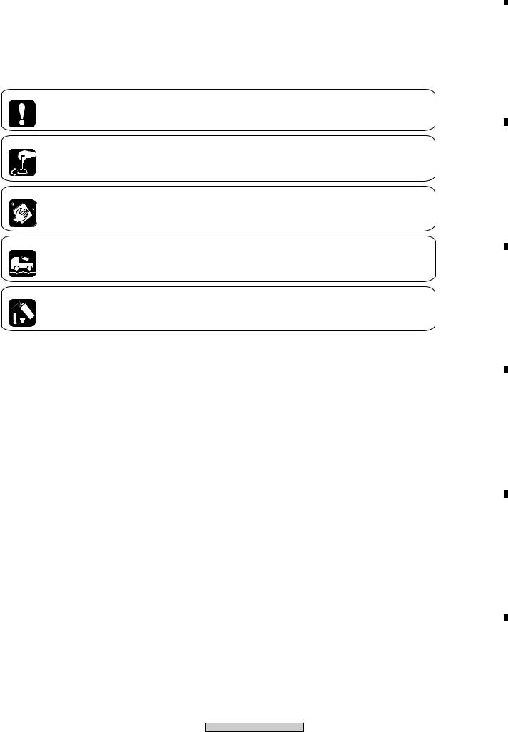
[ Important symbols for good services ]
In this manual, the symbols shown-below indicate that adjustments, settings or cleaning should be made securely. When you find the procedures bearing any of the symbols, be sure to fulfill them:
1. Product safety
You should conform to the regulations governing the product (safety, radio and noise, and other regulations), and should keep the safety during servicing by following the safety instructions described in this manual.
2. Adjustments
To keep the original performances of the product, optimum adjustments or specification confirmation is indispensable. In accordance with the procedures or instructions described in this manual, adjustments should be performed.
3. Cleaning
For optical pickups, tape-deck heads, lenses and mirrors used in projection monitors, and other parts requiring cleaning, proper cleaning should be performed to restore their performances.
4. Shipping mode and shipping screws
To protect the product from damages or failures that may be caused during transit, the shipping mode should be set or the shipping screws should be installed before shipping out in accordance with this manual, if necessary.
5. Lubricants, glues, and replacement parts
Appropriately applying grease or glue can maintain the product performances. But improper lubrication or applying
 glue may lead to failures or troubles in the product. By following the instructions in this manual, be sure to apply the
 prescribed grease or glue to proper portions by the appropriate amount.For replacement parts or tools, the prescribed ones should be used.
3
XV-DV515
A
B
C
D
E
F
|
1 |
|
2 |
|
3 |
|
4 |
|
|
|
|
|
|
||||
|
|
|
|
|

1  2
2  3
3  4
4
CONTENTS
|
|
|
|
SAFETY INFORMATION ...................................................................................................................................... |
2 |
||
A |
|
1. SPECIFICATIONS ............................................................................................................................................ |
5 |
||||
|
2. EXPLODED VIEWS AND PARTS LIST |
8 |
|||||
|
|
|
|
||||
|
|
|
|
2.1 PACKING .................................................................................................................................................... |
8 |
||
|
|
|
|
2.2 EXTERIOR SECTION ............................................................................................................................. |
10 |
||
|
|
|
|
2.3 FRONT SECTION ................................................................................................................................... |
12 |
||
|
|
|
|
2.4 LOADING MECANISM ASSY ................................................................................................................. |
14 |
||
|
|
|
|
2.5 TRAVERSE MECHANISM ASSY |
17 |
||
|
|
|
|
||||
|
|
|
|
3. BLOCK DIAGRAM AND SCHEMATIC DIAGRAM ........................................................................................ |
18 |
||
|
|
|
|
3.1 BLOCK DIAGRAM ................................................................................................................................... |
18 |
||
|
|
|
|
3.2 LOAB ASSY and OVERALL WIRING DIAGRAM ................................................................................... |
20 |
||
B |
|
3.3 DVDM ASSY (1/3) ................................................................................................................................... |
22 |
||||
|
3.4 DVDM ASSY (2/3) |
24 |
|||||
|
|
|
|
||||
|
|
|
|
3.5 DVDM ASSY (3/3) ................................................................................................................................... |
26 |
||
|
|
|
|
3.6 DSP ASSY (1/2) ...................................................................................................................................... |
28 |
||
|
|
|
|
3.7 DSP ASSY (2/2) ...................................................................................................................................... |
30 |
||
|
|
|
|
3.8 6CH AMP ASSY ...................................................................................................................................... |
32 |
||
|
|
|
|
3.9 FM/AM TUNER MODULE |
34 |
||
|
|
|
|
||||
|
|
|
|
................................................................................3.10 CONTROL (1/4), TRADE3 and TRADE2 ASSYS |
36 |
||
|
|
|
|
3.11 CONTROL ASSY (2/4) .......................................................................................................................... |
38 |
||
|
|
|
|
3.12 CONTROL ASSY (3/4) .......................................................................................................................... |
40 |
||
|
|
|
|
3.13 CONTROL (4/4) and HP ASSYS .......................................................................................................... |
42 |
||
C |
|
3.14 POWER ASSY (1/2 ) ............................................................................................................................. |
44 |
||||
|
|
|
|
3.15 POWER (2/2) and TRADE1 ASSYS ..................................................................................................... |
46 |
||
|
|
|
|
3.16 EURO SCART ASSY ............................................................................................................................ |
48 |
||
|
|
|
|
3.17 DISPLAY and LED ASSYS ................................................................................................................... |
50 |
||
|
|
|
|
3.18 WAVEFORMS ....................................................................................................................................... |
52 |
||
|
|
|
|
4. PCB CONNECTION DIAGRAM ..................................................................................................................... |
54 |
||
|
|
|
|
||||
|
|
|
|
4.1 LOAB ASSY |
54 |
||
|
|
|
|
||||
|
|
|
|
4.2 DVDM ASSY ........................................................................................................................................... |
55 |
||
|
|
|
|
4.3 DSP ASSY ............................................................................................................................................... |
57 |
||
|
|
|
|
4.4 6CH AMP ASSY ...................................................................................................................................... |
59 |
||
D |
|
4.5 FM/AM TUNER MODULE ....................................................................................................................... |
61 |
||||
|
4.6 CONTROL ASSY |
62 |
|||||
|
|
|
|
||||
|
|
|
|
4.7 TRADE2 ,TRADE3 and HP ASSYS ........................................................................................................ |
66 |
||
|
|
|
|
4.8 POWER ASSY ........................................................................................................................................ |
68 |
||
|
|
|
|
4.9 TRADE1, EURO SCART, DISPLAY and LED ASSYS ........................................................................... |
72 |
||
|
|
|
|
5. PCB PARTS LIST .......................................................................................................................................... |
76 |
||
|
|
|
|
6. ADJUSTMENT |
83 |
||
|
|
|
|
||||
|
|
|
|
||||
|
|
|
|
7. GENERAL INFORMATION ............................................................................................................................ |
90 |
||
|
|
|
|
7.1 DIAGNOSIS ............................................................................................................................................. |
90 |
||
|
|
|
|
7.1.1 TEST MODE .................................................................................................................................... |
90 |
||
|
|
|
|
7.1.2 DISPLAY SPECIFICATIONS OF THE TEST MODE ...................................................................... |
92 |
||
E |
|
7.1.3 FUNCTIONAL SPECIFICATION OF THE SHORTCUT KEY |
......................................................... 93 |
||||
|
|
|
|
7.1.4 SPECIFICATION OF MODEL INFORMATION DISPALY ............................................................. |
94 |
||
|
|
|
|
7.1.5 FUNCTIONAL SPECIFICATION OF THE SERVICE MODE .......................................................... |
95 |
||
|
|
|
|
7.1.6 MECHANICAL ERROR HISTORY .................................................................................................. |
96 |
||
|
|
|
|
7.1.7 ID NUMBER AND DATA SETTING ............................................................................................... |
101 |
||
|
|
|
|
7.1.8 TROUBLE SHOOTING .................................................................................................................. |
104 |
||
|
|
|
|
||||
|
|
|
|
.........................................................................................................7.1.9 DSP TROUBLE SHOOTING |
107 |
||
|
|
|
|
7.1.10 SEQUENCE AFTER POWER ON ............................................................................................... |
111 |
||
|
|
|
|
7.1.11 PROTECTION CIRCUIT .............................................................................................................. |
112 |
||
|
|
|
|
7.1.12 DISASSEMBLY ............................................................................................................................ |
117 |
||
F |
|
7.2 IC ........................................................................................................................................................... |
126 |
||||
|
7.3 DISC / CONTENT FORMAT PLAYBACK COMPATIBILITY |
142 |
|||||
|
|
|
|
||||
|
|
|
|
7.4 CLEANING ............................................................................................................................................ |
143 |
||
|
|
|
|
8. PANEL FACILITIES ..................................................................................................................................... |
144 |
||
|
|
|
4 |
|
|
|
|
|
|
|
|
XV-DV515 |
|
|
|
|
|
|
|
|
|
|
|
|
1 |
|
2 |
|
3 |
|
4 |
|
|
|
|
|
|
||||
|
|
|
|
|

|
1 |
|
2 |
|
|
1. SPECIFICATIONS
Amplifier section
Continuous Power Output (RMS):
Front, center, surround. . . . . 75 W per channel (1 kHz, 10 % T.H.D., 6Ω)
Subwoofer . . . 75 W (100 Hz, 10 % T.H.D., 6Ω)
Continuous Power Output :
Front, center, surround. . . . . 62 W per channel (1 kHz, 1 % T.H.D., 6Ω )
Subwoofer . . . . 62 W (100 Hz, 1 % T.H.D., 6Ω )
Disc section
Digital audio
characteristics . . . . . . . DVD fs: 96 kHz, 24-bit
Type. . . . . . DVDsystem,video CD system and compact disc digital audio system Frequency response . . . . . . . . . 4 Hz to 44 kHz
Wow and Flutter. . . . . . .Limit of measurement (±0.001 % W.PEAK) or less (JEITA)
FM tuner section
Frequency range . . . . . . . . . . . 87.5 – 108 MHz Antenna . . . . . . . . . . . . . . . .75Ω , unbalanced
AM tuner section
Frequency range
With 9kHz step. . . . . . . 531 kHz to 1,602 kHz
Antenna . . . . . . . . . . . . . . . . . . . Loop antenna
Miscellaneous
Power requirements
European model . . . AC 220-230 V, 50/60 Hz
U.K. model . . . . . . . . . . . AC 230 V, 50/60 Hz
Power consumption
European/U.K. model . . . . . . . . . . . . . 160 W
|
3 |
|
4 |
|
|
Power consumption in standby . . . . . . 0.39 W Dimensions . . .420 (W) x 70 (H) x 403.5 (D) mm Weight . . . . . . . . . . . . . . . . . . . . . . . . . . 7.4 kg
Accessories (DVD/CD receiver)
Remote control . . . . . . . . . . . . . . . . . . . . . . . .1. AA/R6 dry cell batteries. . . . . . . . . . . . . . . . . 2 Video cable (yellow plugs). . . . . . . . . . . . . . . .1
AM loop antenna . . . . . . . . . . . . . . . . . . . . . . 1
FM antenna . . . . . . . . . . . . . . . . . . . . . . . . . .1 Power cord . . . . . . . . . . . . . . . . . . . . . . . . . . .1 Setup Guide. . . . . . . . . . . . . . . . . . . . . . . . . . .1 These operating instructions. . . . . . . . . . . . . .1 Warranty Card . . . . . . . . . . . . . . . . . . . . . . . .1
Speaker System
Front speakers
Enclosure . . . . . . . . Closed-box bookshelf type
(magnetically shielded) System. . . . . . . . . . . . . .15x6 cm 1-way system
Speakers . . . . . . . . . . . . . . .15x6 cm cone type Nominal impedance . . . . . . . . . . . . . . . . . . 6Ω Frequency range . . . . . . . . . . .90 Hz to 20 kHz
Maximum Input Power. . . . . . . . . . . . . . . 75 W Dimensions . . . . . 78 (W) x 210 (H) x 82 (D) mm Weight . . . . . . . . . . . . . . . . . . . . . . . . . . 0.7 kg
Center speaker
Enclosure . . . . . . . . Closed-box bookshelf type (magnetically shielded)
System. . . . . . . . . . . . . .15x6 cm 1-way system Speakers . . . . . . . . . . . . . . .15x6 cm cone type
Nominal impedance . . . . . . . . . . . . . . . . . . 6Ω Frequency range . . . . . . . . . . .78 Hz to 20 kHz Maximum Input Power. . . . . . . . . . . . . . . 75 W Dimensions . . . . . 240 (W) x 85 (H) x 96 (D) mm Weight . . . . . . . . . . . . . . . . . . . . . . . . . 0.75 kg
5
XV-DV515
A
B
C
D
E
F
|
1 |
|
2 |
|
3 |
|
4 |
|
|
|
|
|
|
||||
|
|
|
|
|
|
1 |
|
2 |
|
3 |
|
4 |
|
|
|
|
|
|
A |
Subwoofer |
|
|
|
|
|
|
Enclosure |
|
Bass-reflex floor type |
|
|
|
||
|
|
. . . . . . |
• Specifications and design subject to |
||||
|
|
|
|
(magnetically shielded) |
|||
|
|
System. . . . . . . |
. . . . . . |
. . .16 cm 1-way system |
|
possible modification without notice, due |
|
|
|
Speaker . . . . . . |
. . . . . . |
. . . . . 16 cm cone type |
|
to improvements. |
|
|
|
Nominal impedance . . . |
. . . . . . . . . . . . . . . . 6Ω |
|
|
|
|
|
|
. . . . .Frequency range |
. . . . . 35 Hz to 2.8 kHz |
|
This product includes FontAvenue® |
|
|
|
|
Maximum Input Power |
75 W |
|
|
||
|
|
|
fonts licenced by NEC corporation. |
|
|||
|
|
Dimensions |
130 (W) x 360 (H) x 360 (D) mm |
|
FontAvenue is a registered trademark |
|
|
|
|
||||||
|
|
Weight . . . . . . . |
. . . . . . |
. . . . . . . . . . . . . 4.5 kg |
|
of NEC Corporation. |
|
|
|
|
|
|
|
|
|
|
|
|
Accessories (Speaker system) |
|
|
|
|
|
|
|
|
This product incorporates copyright |
|||
|
|
|
Speaker cables |
6. |
|||
|
|
|
protection technology that is protected |
||||
|
|
|
|
|
|||
B |
Non-slip pads(Small) |
20 |
by method claims of certain U.S. patents |
||||
and other intellectual property rights |
|||||||
|
|
|
Non-slip pads(Large) |
4 |
|||
|
|
|
owned by Macrovision Corporation and |
||||
|
|
|
|
|
|||
|
|
|
|
|
other rights owners. Use of this copyright |
||
|
|
|
|
|
protection technology must be authorized |
||
|
|
|
|
|
by Macrovision Corporation, and is |
||
|
|
|
|
|
intended for home and other limited uses |
||
|
|
|
|
|
only unless otherwise authorized by |
||
|
|
|
|
|
|||
|
|
|
|
|
Macrovision Corporation. Reverse |
||
|
|
|
|
|
engineering or disassembly is prohibited. |
||
|
|
|
|
|
|
||
|
|
|
|
|
|
||
|
|
|
|
|
This product is intended for household |
||
|
|
|
|
|
purposes. Any failure due to use for other |
||
C |
|
|
than household purposes (such as long- |
||||
|
|
|
|
|
term use for business purposes in a |
||
|
|
|
|
|
restaurant or use in a car or ship) and |
||
|
|
|
|
|
which requires repair will be charged for |
||
|
|
|
|
|
even in the warranty period. |
KO41_En |
|
|
|
|
|
|
|
|
|
|
|
|
|
|
|
|
|
|
|
|
|
|
|
|
|
D
|
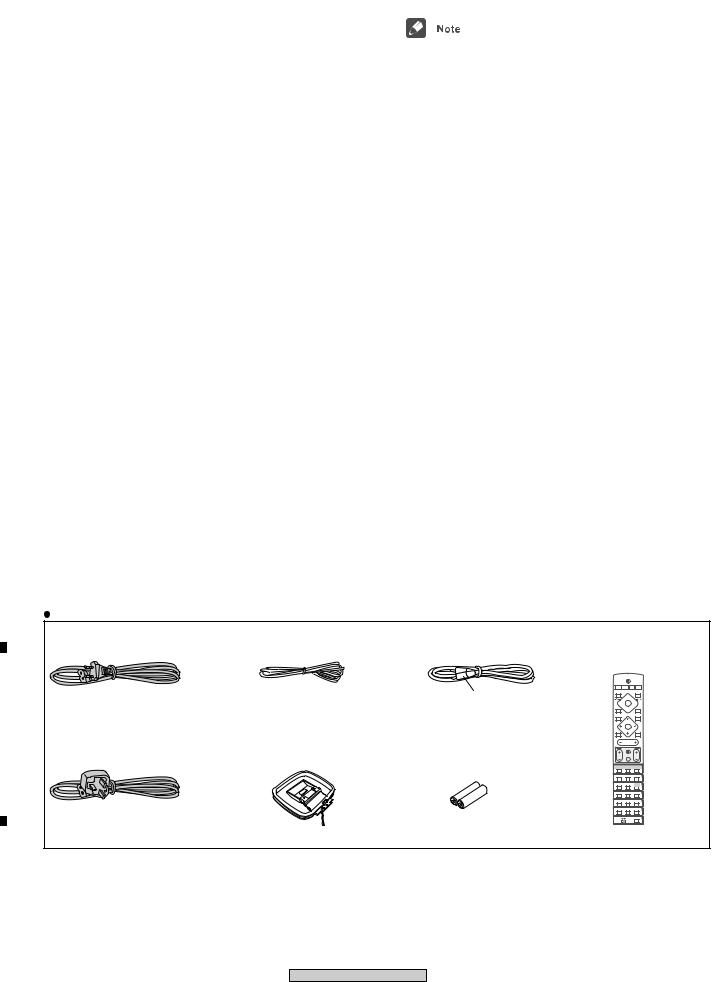
Accessories |
|
|
|
|
|
|
• Power cord |
• FM Antenna |
• Video Cord |
• Remote Control Unit |
||
|
(MYXJ, MYXJN : ADG1154) |
(ADH7030) |
(L = 1.5m)(VDE1065) |
(XXD3059 for XV-DV515) |
||
|
|
|
|
(XXD3058 for XV-DV313) |
||
|
|
|
|
|
STANDBY/ON |
|
|
|
|
|
CD |
FM/AM |
L1/L2 |
|
|
|
|
DVD |
TUNER TV LINE |
|
|
|
|
Yellow |
DISPLAY |
3 |
OPEN/CLOSE |
|
|
|
1 |
¡ |
||
|
|
|
|
|
8 |
0 |
|
|
|
|
4 |
7 |
4 |
|
|
|
|
|
|
|
|
|
|
|
DVD MENU |
|
RETURN |
|
|
|
|
|
TUNE+ |
|
|
|
|
|
ST– |
ST+ |
|
E |
|
|
|
|
ENTER |
|
• Power cord |
• AM Loop Antenna |
• Dry Cell Battery |
MUTE |
TUNE– |
SOUND |
|
|
|
VOLUM E |
|
|||
|
|
|
|
|
MASTER |
|
|
(NVXJ, NVXJN : ADG1156) |
(ATB7009) |
(R6P, AA) |
|
TV CONTROL |
|
|
CH |
INPUT |
VOL |
|||
|
|
|
|
BASS MODE |
DIALOGUE |
VIRTUAL SB |
|
|
|
|
AUTO |
SURROUND |
ADVANCED |
|
|
|
|
PROGRAM |
REPEAT |
RANDOM |
|
|
|
|
AUDIO |
SUBTITLE |
ANGLE |
|
|
|
|
ZOOM |
TOP MENU |
HOME |
|
|
|
|
MENU |
||
|
|
|
|
1 |
2 |
3 |
|
|
|
|
SYSTEM |
TEST TONE |
CH LEVEL |
|
|
|
|
SETUP |
||
|
|
|
|
4 |
5 |
6 |
|
|
|
|
DIMMER |
QUIET/ |
TIMER/ |
|
|
|
|
MIDNIGHT |
CLOCK |
|
|
|
|
|
7 |
8 |
9 |
|
|
|
|
|
FOLDER– |
FOLDER+ |
|
|
|
|
CLR |
0 |
ENTER |
|
|
|
|
|
|
WIRELESS |
|
|
|
|
MAIN |
SUB |
ROOM SETUP |
F
6
XV-DV515
|
1 |
|
2 |
|
3 |
|
4 |
|
|
|
|
|
|
||||
|
|
|
|
|

|
1 |
|
2 |
|
3 |
|
4 |
|
|
|
|
|
|
A
B
C
D
E
F
7
XV-DV515
|
1 |
|
2 |
|
3 |
|
4 |
|
|
|
|
|
|
||||
|
|
|
|
|
1  2
2  3
3  4
4
2. EXPLODED VIEWS AND PARTS LIST
NOTES: |
Parts marked by "NSP" are generally unavailable because they are not in our Master Spare Parts List. |
|
A |
The |
mark found on some component parts indicates the importance of the safety factor of the part. |
Therefore, when replacing, be sure to use parts of identical designation.  Screws adjacent to
  mark on product are used for disassembly.
 For the applying amount of lubricants or glue, follow the instructions in this manual. (In the case of no amount instructions, apply as you think it appropriate.)
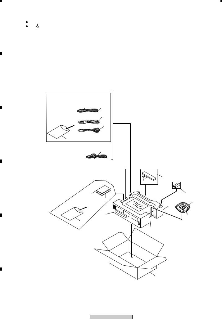
2.1 PACKING
B
(for MYXJ,
MYXJN Type) 1
4
2
C
22
(for NVXJ,
NVXJN Type) 1
17 

5
6
D
10 - 16 |
7 |
|
|
||
(MYXJ,MYXJN 8,9 |
3 |
|
Type Only) |
||
19 |
||
|
18
22
20
E
21
F
8
XV-DV515
|
1 |
|
2 |
|
3 |
|
4 |
|
|
|
|
|
|
||||
|
|
|
|
|

1  2
2  3
3  4
4
(1) PACKING PARTS LIST
Mark No. |
Description |
Part No. |
|
> |
1 |
Power Cord |
See Contrast table(2) |
|
2 |
FM Wire Antena |
ADH7030 |
|
3 |
AM Loop Antenna |
ATB7009 |
|
4 |
Video Cord |
VDE1065 |
|
5 |
Remote Control |
See Contrast table(2) |
|
6 |
Battery Cover |
XZN3130 |
NSP |
7 |
Dry Cell Batteries(R6P,AA) |
VEM1031 |
|
8 |
Operating Instructions |
See Contrast table(2) |
|
|
(English) |
|
|
9 |
Operating Instructions Basic |
See Contrast table(2) |
|
|
(English, French) |
|
|
10 |
Operating Instructions Basic |
See Contrast table(2) |
|
|
(German, Italian) |
|
|
11 |
Operating Instructions |
See Contrast table(2) |
|
|
(Dutch, Spanish) |
|
|
12 |
Operating Instructions |
See Contrast table(2) |
|
|
(German) |
|
|
13 |
Operating Instructions |
See Contrast table(2) |
|
|
(Dutch) |
|
|
14 |
Operating Instructions |
See Contrast table(2) |
|
|
(French) |
|
|
15 |
Operating Instructions |
See Contrast table(2) |
|
|
(Italian) |
|
|
16 |
Operating Instructions |
See Contrast table(2) |
|
|
(Spanish) |
|
NSP 17 |
Warranty Card |
ARY7065 |
|
|
18 |
Front Pad |
XHA3140 |
|
19 |
Rear Pad |
XHA3139 |
|
20 |
Packing Sheet |
AHG7010 |
|
21 |
Packing Case |
See Contrast table(2) |
NSP 22 |
Polyethylene Bag |
Z21-038 |
|
(2)CONTRAST TABLE
XV-DV515/MYXJ, /NVXJ, XV-DV313/MYXJN and NVXJN types are constructed the same except for the following:
Mark |
No. |
Symbol and Description |
|
Part No. |
|
|
Remarks |
|||
|
|
|
|
|
|
|||||
XV-DV515 |
XV-DV515 |
XV-DV313 |
XV-DV313 |
|||||||
|
|
|
|
|||||||
|
|
|
MYXJ |
NVXJ |
|
MYXJN |
NVXJN |
|
||
|
|
|
|
|
|
|
|
|
||
> |
1 |
Power Cord |
ADG1154 |
ADG1156 |
|
ADG1154 |
ADG1156 |
|
||
|
5 |
Remote Control |
XXD3059 |
XXD3059 |
|
XXD3058 |
XXD3058 |
|
||
|
8 |
Operating Instructions (English) |
XRB3024 |
XRB3024 |
|
XRB3023 |
XRB3023 |
|
||
|
9 |
Operating Instructions Basic |
XRE3075 |
XRE3075 |
|
XRE3072 |
XRE3072 |
|
||
|
|
(English, French) |
|
|
|
|
|
|
|
|
|
10 |
Operating Instructions Basic |
XRC3106 |
Not used |
|
XRC3101 |
Not used |
|
||
|
|
(German, Italian) |
|
|
|
|
|
|
|
|
|
11 |
Operating Instructions Basic |
XRC3107 |
Not used |
|
XRC3102 |
Not used |
|
||
|
|
(Dutch, Spanish) |
|
|
|
|
|
|
|
|
|
12 |
Operating Instructions(German) |
XRC3094 |
Not used |
|
XRC3084 |
Not used |
|
||
|
13 |
Operating Instructions(Dutch) |
XRC3095 |
Not used |
|
XRC3085 |
Not used |
|
||
|
14 |
Operating Instructions(French) |
XRC3096 |
Not used |
|
XRC3086 |
Not used |
|
||
|
15 |
Operating Instructions(Italian) |
XRC3097 |
Not used |
|
XRC3087 |
Not used |
|
||
|
16 |
Operating Instructions(Spanish) |
XRC3098 |
Not used |
|
XRC3088 |
Not used |
|
||
|
21 |
Packing Case |
XHD3380 |
XHD3380 |
|
XHD3351 |
XHD3351 |
|
||
|
|
|
|
|
|
|
|
|
|
|
|
|
|
|
|
|
|
|
9 |
||
|
|
|
XV-DV515 |
|
|
|
||||
|
|
|
|
|
|
|
|
|||
A
B
C
D
E
F
|
1 |
|
2 |
|
3 |
|
4 |
|
|
|
|
|
|
||||
|
|
|
|
|
1  2
2  3
3  4
4
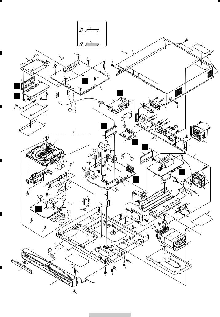
2.2 EXTERIOR SECTION |
|
|
|
A |
|
NON-CONTACT |
|
|
SIDE |
|
|
|
|
|
65 |
|
|
CONTACT SIDE |
49 |
|
|
|
|
|
|
48 |
65 |
|
64 |
26 |
|
|
|
|
|
28 |
42 |
64 |
|
65
64
6
B
G
C
64
C
D
E
|
2 |
|
|
34 |
|
|
|
34 |
J |
|
|
|
|
|
|
F |
|
|
|
||
|
|
|
|
|
|
|
|
|
||
|
|
|
|
|
64 |
|
|
|
|
|
|
|
|
|
|
|
|
|
E |
|
|
|
|
|
|
|
|
|
|
5 |
|
|
|
|
|
|
|
|
|
|
|
|
|
|
|
64 |
|
|
|
|
|
|
4 |
29 |
|
|
|
|
|
|
|
|
|
||
64 |
|
|
|
|
|
|
|
|
|
|
|
|
|
|
|
|
|
|
|
|
|
|
|
|
|
A |
B |
|
|
20 |
|
21 |
|
|
|
|
|
|
|
|
|
||
|
|
30 |
|
|
|
|
|
|
I |
|
|
|
44 |
|
|
|
|
|
|
J |
|
|
|
|
|
|
|
|
H |
22 |
|
|
|
|
|
|
|
51 |
|
|
|
||
|
|
|
|
|
|
|
|
|
|
|
|
71 |
|
|
Refer to |
|
|
|
7 |
|
|
|
|
|
"2.4 LOADING |
|
|
|
|
L |
||
|
|
|
|
MECHANISM ASSY". |
|
|
10 |
|||
|
|
|
|
|
|
|
|
|
K 14 |
|
|
|
|
|
|
|
|
I |
|
64 |
9 |
|
|
|
|
|
|
|
|
|
|
|
|
|
|
|
|
|
H |
|
|
|
|
|
|
|
|
|
71 |
17 |
|
|
|
L |
|
|
|
|
G |
64 |
|
|
|
|
|
|
|
|
|
|
|
|
|
|
||
|
|
|
|
F |
|
C |
|
15 |
|
|
|
54 |
|
D |
E |
|
70 |
|
|
||
|
|
|
|
|
|
|
|
|
||
|
|
|
|
|
16 |
|
|
|
J |
|
|
|
|
|
|
|
|
|
|
|
|
|
55 |
|
|
|
37 |
|
|
|
8 |
|
|
|
|
|
|
|
|
|
64 |
|
|
|
53 |
56 |
|
H |
|
64 |
|
64 |
|
|
|
|
|
|
|
|
|||||
|
|
|
|
|
|
62 |
||||
56 |
1 |
|
|
53 G |
27 |
|
|
40 |
|
|
|
|
|
|
27 |
71 |
|||||
|
|
|
|
|
|
|
|
|
60 |
|
|
B |
|
|
52 |
|
|
|
|
|
|
|
|
|
32 |
|
|
|
45 |
|
||
|
|
|
F |
|
|
|
|
|||
|
|
|
|
|
|
|
|
62 |
||
|
|
|
|
|
|
|
|
|
||
|
|
|
|
E |
|
|
|
|
|
39 |
|
|
|
|
D |
|
|
|
|
|
|
|
56 |
|
|
C |
|
|
|
|
|
|
|
|
|
|
|
|
|
|
|
35 |
|
|
|
|
|
|
|
|
|
|
|
|
|
56 |
|
|
|
|
|
|
|
|
|
|
|
36 |
|
|
|
|
|
|
|
|
A |
|
|
|
|
|
18 |
64 |
|
|
|
|
68 |
|
|
|
|
|
|
B |
|
|
|
64 |
|
|
|
|
|
|
47 |
19 |
50 |
|
33 |
39 |
|
|
||||
|
|
|
|
||
|
|
|
33 |
39 |
|
|
|
|
|
|
Refer to |
64 |
|
|
"2.3 FRONT PANEL". |
|
46 64 67
 64 65 67
64 67 64
67
67
64
64
K
62
D
3
|
71 |
62 |
|
|
|
59 |
|
61 |
|
71 |
|
|
|
|
62 |
|
59 |
|
71 |
|
66 |
|
L |
|
K |
23 |
66 |
|
F |
68 |
|
10
XV-DV515
64
38
24
57
63
58
60 |
62 |
|
|
59 |
|
43
62
66
13
25
|
1 |
|
2 |
|
3 |
|
4 |
|
|
|
|
|
|
||||
|
|
|
|
|
1  2
2  3
3  4
4
(1) EXTERIOR SECTION PARTS LIST
Mark No. |
Description |
Part No. |
Mark No. |
Description |
Part No. |
1 |
DVDM ASSY |
AWM7808 |
36 |
Bottom Plate |
AEC7420 |
2 |
DSP ASSY |
AWX8253 |
37 |
Barrier S |
AEC7429 |
3 |
6CH AMP |
AZW7283 |
38 |
Fan Cover |
AMR7440 |
4 |
FM/AM TUNER MODULE |
AXQ7229 |
39 |
Card Spacer |
DNK2769 |
5 |
CONTROL ASSY |
See Contrast table(2) |
NSP 40 |
Spacer |
PNY-404 |
6 |
TRADE3 ASSY |
XWZ3714 |
41 |
• • • • • • |
|
7 |
TRADE2 ASSY |
XWX3071 |
42 |
Cushion Rubber |
XEB3036 |
8 |
POWER ASSY |
XWZ3716 |
43 |
Trans Barrier |
XEC3046 |
9 |
TRADE1 ASSY |
XWZ3725 |
44 |
DSP Barrier |
XEC3047 |
10 |
EURO SCART ASSY |
XWZ3724 |
45 |
Locking Card Spacer |
XEC3051 |
11 |
• • • • • • |
|
46 |
EURO Cover |
XMR3081 |
NSP 12 |
Loading Mechanism ASSY |
VWT1208 |
47 |
Tray Cap |
XAK3389 |
> 13 |
Power Transformer (T1) |
XTS3066 |
48 |
Bonnet Case |
XZN3129 |
> 14 |
Fuse (FU1 : T2.5A) |
REK1026 |
49 |
Caution Label |
VRW1872 |
> 15 |
Fuse (FU2 : T5.0A) |
REK1029 |
NSP 50 |
Name Label |
See Contrast table(2) |
16 |
30P F.F.C/60V |
XDD3128 |
NSP 51 |
DVD Assy |
AXA7121 |
17 |
18P F.F.C/60V |
XDD3129 |
52 |
Connector Assy |
PG05KK-E25 |
18 |
15P F.F.C/60V |
XDD3130 |
53 |
Cushion |
AEB7267 |
19 |
5P F.F.C/60V |
XDD3131 |
54 |
Adapter02 L |
ANW7267 |
20 |
13P F.F.C/60V |
XDD3132 |
55 |
Adapter02 R |
ANW7268 |
21 |
17P F.F.C/60V |
XDD3133 |
56 |
Screw |
BPZ30P080FMC |
22 |
7P F.F.C/60V |
XDD3134 |
NSP 57 |
AMP Module 6ch |
AXQ7242 |
NSP 23 |
Chassis |
XNA3017 |
58 |
DC Fan Motor |
AXM7025 |
24 |
Rear Panel |
See Contrast table(2) |
59 |
FET Bracket A |
ANG7418 |
25 |
Trans Frame |
XNG3106 |
60 |
Fan Plate |
See Contrast table(2) |
26 |
Spacer |
XEC3052 |
NSP 61 |
Heat Sink |
See Contrast table(2) |
27 |
Control Angle |
XNG3108 |
62 |
Screw |
BBZ30P140FMC |
28 |
DSP Holder |
XNG3109 |
63 |
Screw |
BBZ30P300FZK |
29 |
EURO GND |
XNG3111 |
64 |
Screw |
BBZ30P060FMC |
30 |
DSP Shield |
XNK3010 |
65 |
Screw |
BBZ30P080FNI |
31 |
• • • • • • |
|
66 |
Screw |
BBZ40P060FMC |
32 |
PCB Spacer |
AEB7206 |
67 |
Screw |
BPZ30P080FZK |
33 |
S Cover |
AEB7262 |
68 |
Screw |
CBZ30P080FMC |
NSP 34 |
PCB Spacer(3x6) |
AEC7156 |
69 |
• • • • • • |
|
35 |
Locking Card Spacer |
AEC7372 |
70 |
Screw |
VPZ30P140FMC |
|
|
|
71 |
Screw |
VBZ30P080FMC |
A
B
C
D
(2)CONTRAST TABLE
XV-DV515/MYXJ, /NVXJ, XV-DV313/MYXJN and NVXJN types are constructed the same except for the following:
Mark |
No. |
Symbol and Description |
|
Part No. |
|
Remarks |
E |
||||
|
|
|
|
|
|
||||||
XV-DV515 |
XV-DV515 |
XV-DV313 |
XV-DV313 |
|
|
|
|||||
|
|
|
|
|
|||||||
|
|
|
MYXJ |
NVXJ |
MYXJN |
NVXJN |
|
|
|||
|
|
|
|
|
|
|
|
|
|||
|
5 |
CONTROL ASSY |
XWZ3710 |
XWZ3710 |
XWZ3703 |
XWZ3703 |
|
|
|
|
|
|
24 |
Rear Panel |
XNC3238 |
XNC3239 |
XNC3217 |
XNC3208 |
|
|
|
|
|
NSP |
50 |
Name Label |
XAX3381 |
XAX3381 |
XAX3375 |
XAX3375 |
|
|
|
|
|
|
|||||||||||
|
60 |
Fan Plate |
ANG7462 |
ANG7462 |
ANG7425 |
ANG7425 |
|
|
|||
|
61 |
Heat Sink |
ANH7166 |
ANH7166 |
ANH7161 |
ANH7161 |
|
|
|||
|
|
|
|
|
|
|
|
|
F |
||
|
|
|
|
|
|
|
|
|
|||
|
|
|
|
|
|
|
11 |
|
|
|
|
|
|
|
XV-DV515 |
|
|
|
|
||||
|
|
|
|
|
|
|
|
|
|
||
|
1 |
|
2 |
|
3 |
|
4 |
|
|
|
|
|
|
||||
|
|
|
|
|
|
1 |
|
2 |
|
3 |
|
4 |
|
|
|
|
|
|
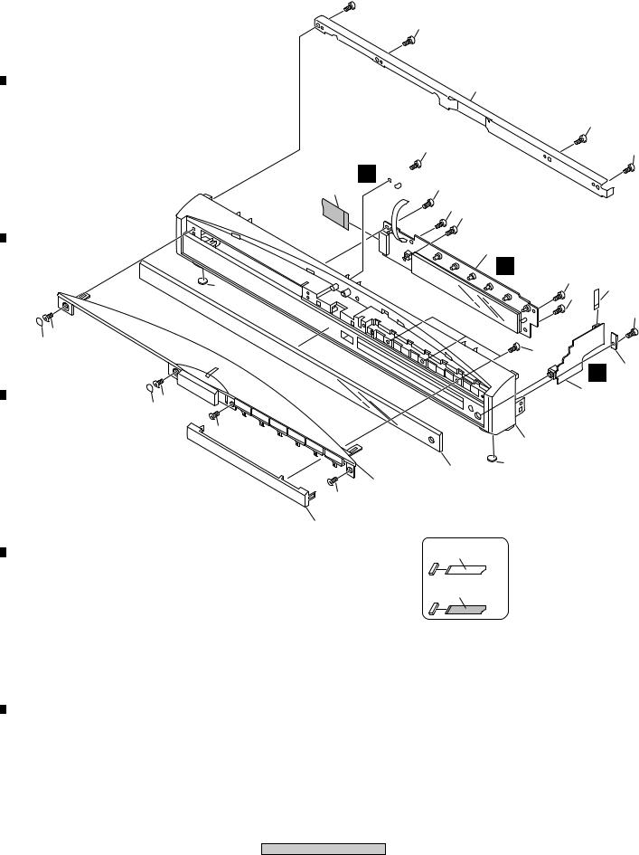
2.3 FRONT SECTION
15 A 
15
6
15
15 |
15 |
B |
2 |
N 

15
4
15
15
|
|
1 |
|
|
|
|
M |
|
|
|
7 |
15 |
|
|
|
15 |
|
5 |
|
|
|
|
||
|
|
|
|
|
C |
|
|
|
15 |
|
|
|
|
|
|
17 |
|
|
|
|
8 |
15 |
|
|
|
|
I |
|
|
|
|
|
19 |
|
|
|
|
|
|
|
|
|
3 |
|
|
17 |
|
|
|
|
8 |
|
|
|
|
17 |
|
|
|
|
|
12 |
|
|
|
|
7 |
|
|
D |
|
9 |
|
|
|
|
13 |
|
|
|
|
17 |
|
|
11
NON-CONTACT
SIDE
CONTACT SIDE
E
F
12
XV-DV515
|
1 |
|
2 |
|
3 |
|
4 |
|
|
|
|
|
|
||||
|
|
|
|
|

1  2
2  3
3  4
4

 FRONT SECTION PARTS LIST
Mark No. |
Description |
Part No. |
|
|
1 |
DISPLAY ASSY |
XWZ3720 |
A |
|
2 |
LED ASSY |
XWZ3721 |
||
|
||||
3 |
HP ASSY |
XWZ3715 |
|
|
4 |
15P F.F.C/60V |
XDD3130 |
|
|
5 |
5P F.F.C/60V |
XDD3131 |
|
|
6 |
Top Frame |
XNG3107 |
|
|
7 |
Leg |
AEB7090 |
|
|
|
||||
8 |
Rubber Cover |
XEB3034 |
|
|
9 |
Display Panel |
See Contrast table(2) |
|
|
NSP 10 |
Front Panel Assy |
XXG3160 |
|
|
11 |
Front Cap |
XAK3390 |
B |
|
12 |
Front Panel |
XMB3122 |
||
|
||||
13 |
Top Panel Assy |
XZN3131 |
|
|
14 |
• • • • • |
|
|
|
15 |
Screw |
BPZ30P080FZK |
|
|
16 |
• • • • • |
|
|
|
|
|
|||
17 |
Screw |
PBA1096 |
|
|
18 |
• • • • • |
|
|
|
NSP 19 |
HP Press ASSY |
• • • • • |
|
C
(2)CONTRAST TABLE
XV-DV515/MYXJ, /NVXJ, XV-DV313/MYXJN and /NVXJN types are constructed the same except for the following:
Mark |
No. |
Symbol and Description |
|
Part No. |
|
|
Remarks |
|
|
|
|
|
|
|
|
|
|||||
XV-DV515 |
XV-DV515 |
XV-DV313 |
XV-DV313 |
|
|
|||||
|
|
|
|
|
||||||
|
|
|
MYXJ |
NVXJ |
|
MYXJN |
NVXJN |
|
|
|
|
|
|
|
|
|
|
|
|
D |
|
|
9 |
Display Panel |
XAK3410 |
XAK3410 |
|
XAK3408 |
XAK3408 |
|
||
|
|
|
|
|||||||
|
|
|
|
|
|
|
|
|
|
|
|
|
|
|
|
|
|
|
|
|
|
|
|
|
|
|
|
|
|
|
|
|
E
F
13
XV-DV515
|
1 |
|
2 |
|
3 |
|
4 |
|
|
|
|
|
|
||||
|
|
|
|
|
1 |
2 |
|
|
3 |
|
|
4 |
|
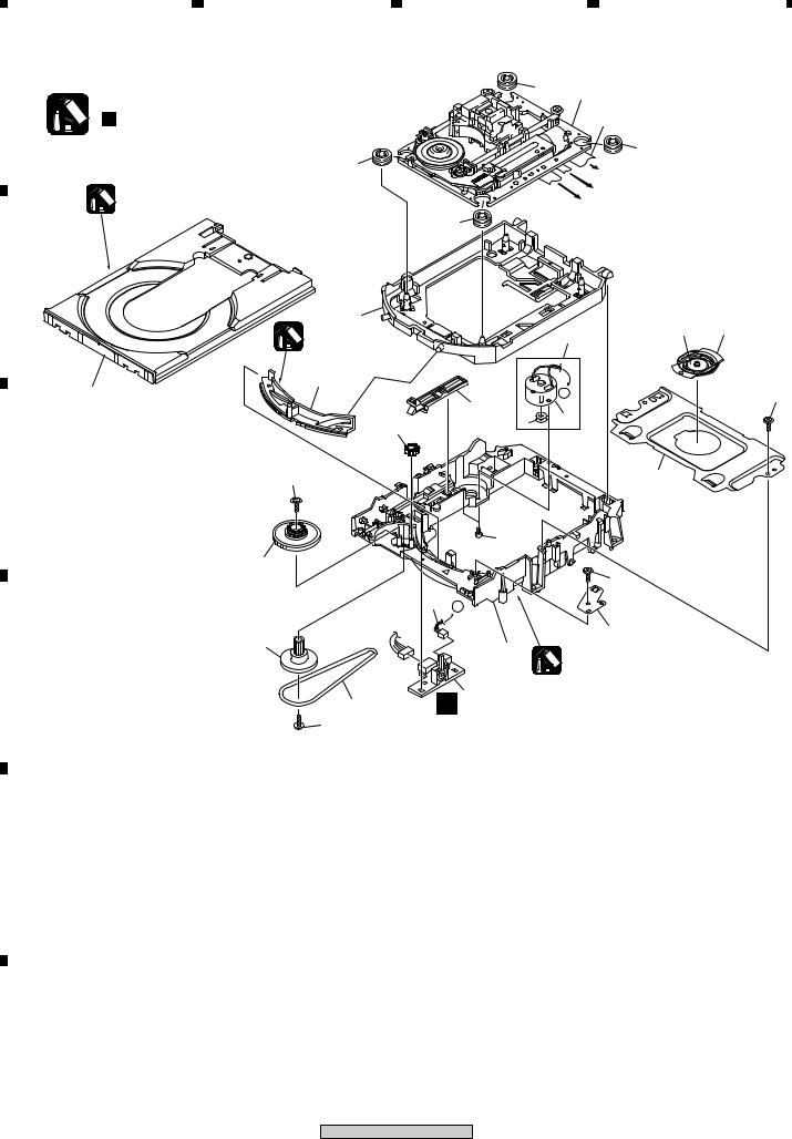
2.4 LOADING MECHA ASSY |
|
|
|
|
|
|
|
|
Note : |
|
|
|
|
8 |
|
Refer to |
|
A |
|
|
|
|
2 |
|
||
Refer to |
|
|
|
|
|
"2.5 TRAVERSE MECHA. ASSY-S". |
||
" |
Application of Lubricant". |
|
|
|
|
|
6 |
|
|
|
|
|
|
|
|
8 |
|
|
8 |
|
|
|
|
|
To DVDM CN101 (Pickup Assy-S) |
|
|
|
|
|
|
|
|
||
|
Daifree |
|
|
|
|
|
To DVDM CN104 (Stepping Motor) |
|
|
|
|
|
|
To DVDM CN105 (Spindle Motor) |
|
||
|
GEM1036 |
|
|
|
|
|
||
|
|
|
|
|
|
|
|
|
|
|
|
|
8 |
|
|
|
|
B |
|
|
|
|
|
|
|
|
|
12 |
|
|
|
|
|
18 |
20 |
|
Lubricating Oil |
|
|
|
|
3 |
||
|
|
|
|
|
|
|
||
|
GYA1001 |
|
|
|
|
|
|
|
|
|
|
|
|
|
|
|
|
23 |
13 |
|
|
|
|
A |
|
|
|
|
|
17 |
|
|
22 |
||
|
|
|
|
|
5 |
|
|
|
|
|
16 |
|
4 |
|
|
|
|
|
|
|
|
|
|
|
|
|
C |
22 |
|
|
|
|
|
19 |
|
|
|
|
|
21 |
|
|
|
|
|
15 |
|
|
|
|
|
|
|
|
|
|
|
|
|
|
22 |
|
|
|
|
7 |
A |
|
|
|
|
|
|
|
|
|
|
|
|
|
|
14 |
|
|
|
|
|
10 |
|
|
|
|
11 |
|
|
|
|
|
|
|
|
|
|
Lubricating Oil |
|
||
|
|
|
|
|
|
|
||
D |
|
|
|
|
|
GYA1001 |
|
|
|
9 |
|
|
A 1 |
|
|
|
|
|
22 |
|
|
|
|
|
|
|
E
F
14
XV-DV515
|
1 |
|
2 |
|
3 |
|
4 |
|
|
|
|
|
|
||||
|
|
|
|
|

1  2
2  3
3  4
4

 LOADING MECHA ASSY PARTS LIST
Mark No. |
Description |
Part No. |
|
|
NSP 1 |
LOAB Assy |
See Contrast table(2) |
A |
|
2 |
Traverse Mechanism Assy-S |
VXX2871 |
||
|
||||
3 |
Loading Motor Assy |
VXX2872 |
|
|
4 |
Motor Pulley |
PNW1634 |
|
|
5 |
Motor |
VXM1105 |
|
|
6 |
Flexible Cable (24P) |
VDA1947 |
|
|
|
||||
7 |
Connector Assy 2P |
VKP2253 |
|
|
|
||||
8 |
Floating Rubber |
VEB1351 |
|
|
9 |
Belt |
VEB1330 |
|
|
10 |
Stabilizer |
VNE2253 |
|
|
11 |
Loading Base |
VNL1917 |
B |
|
12 |
Float Base DVD |
VNL1918 |
||
|
||||
13 |
Drive Cam |
VNL1919 |
|
|
14 |
Gear Pulley |
VNL1921 |
|
|
15 |
Loading Gear |
VNL1922 |
|
|
16 |
Drive Gear |
VNL1923 |
|
|
17 |
SW Lever |
VNL1925 |
|
|
|
||||
18 |
Clamper Plate |
VNE2251 |
|
|
19 |
Bridge |
VNE2252 |
|
|
20 |
Clamper |
VNL1924 |
|
|
21 |
Screw |
JGZ17P028FMC |
|
|
22 |
Screw |
Z39-019 |
C |
|
23 |
Tray |
See contrast table(2) |
|
|
|
|
|
|
|
|
|
|
|
(2)CONTRAST TABLE
XV-DV515/MYXJ, /NVXJ, XV-DV313/MYXJN and /NVXJN types are constructed the same except for the following:
Mark |
No. |
Symbol and Description |
|
Part No. |
|
Remarks |
|
|
||
|
|
|
|
|
||||||
XV-DV515 |
XV-DV515 |
XV-DV313 |
XV-DV313 |
D |
||||||
|
|
|
|
|||||||
|
|
|
MYXJ |
NVXJ |
MYXJN |
NVXJN |
|
|
|
|
|
|
|
|
|
|
|
|
|
|
|
NSP |
1 |
LOAB ASSY |
VWG2346 |
VWG2346 |
VWG2279 |
VWG2279 |
|
|
|
|
|
23 |
Tray |
VNL1920 |
VNL1920 |
VNL1950 |
VNL1950 |
|
|
|
|
|
|
|
|
|
|
|
|
|
|
|
|
|
|
|
|
|
|
|
|
|
|
|
|
|
|
|
|
|
|
|
|
|
E
F
15
XV-DV515
|
1 |
|
2 |
|
3 |
|
4 |
|
|
|
|
|
|
||||
|
|
|
|
|
|
1 |
2 |
3 |
4 |
|
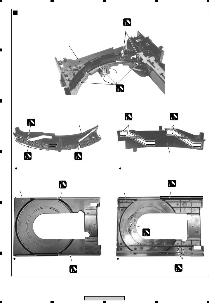
Application of Lubricant |
|
|
|
A |
|
|
Lubricating Oil |
|
|
|
GYA1001 |
|
|
|
|
|
Around the shaft |
|
|
|
No. 11 |
|
|
|
|
Loading Base |
|
|
B |
|
|
|
|
|
|
|
Lubricating Oil |
|
|
|
|
GYA1001 |
|
|
|
No. 13 |
Lubricating Oil |
Lubricating Oil |
|
Lubricating Oil |
GYA1001 |
GYA1001 |
|
|
Drive Cam |
Inner side of a ditch |
Inner side of a ditch |
|
C |
GYA1001 |
|
|
|
|
Lubricating Oil |
Lubricating Oil |
|
No. 13 |
|
GYA1001 |
GYA1001 |
|
Drive Cam |
|
Front View |
|
Rear View |
|
D |
|
|
|
|
|
No. 23 |
Daifree |
No. 23 |
Daifree |
|
GEM1036 |
|||
|
GEM1036 |
|||
|
Tray |
Tray |
Concave of unevenness |
|
|
Concave of unevenness |
|||
|
|
|
|
|
E |
|
|
Inner side of a ditch |
|
|
|
|
|
|
|
|
|
Daifree |
|
|
|
|
GEM1036 |
|
|
Top View |
|
Bottom View |
Side of the rib |
|
|
Concave of unevenness |
|
|
|
|
|
|
|
|
|
Daifree |
|
Daifree |
|
|
|
GEM1036 |
|
|
|
GEM1036 |
|
|
|
|
|
|
|
F |
|
|
|
|
|
16 |
XV-DV515 |
|
|
|
|
|
|
|
|
1 |
2 |
3 |
4 |
1  2
2  3
3  4
4
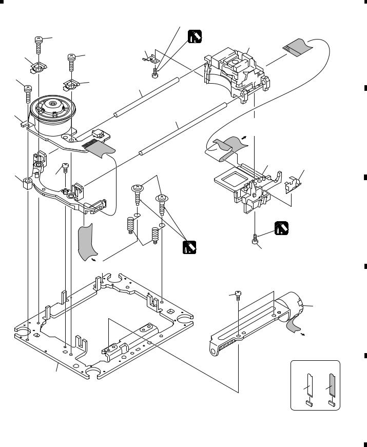
2.5 TRAVERSE MECHA ASSY-S |
15 (Torque : 0.15 |
± 0.01 N•m) |
||
|
|
|||
|
17 |
Silicone Adhesive |
|
|
|
GEM1037 |
|
||
|
|
3 |
||
|
8 |
|
|
|
|
|
|
|
|
10 |
17 |
|
|
|
17
10
7
1
6
To
DVDM CN101
(Pickup Assy)
14
9
13 |
4 (Adjustment screw) |
|
16 |
||
|
|
|
Silicone Adhesive |
||
|
|
GEM1037 |
|
|
5 |
Screw Tight |
15 (Torque : 0.15 ± 0.01 N•m) |
||
GYL1001 |
||||
(Adjustment |
||||
|
|
|
||
spring) |
|
|
|
|
To DVDM CN105 |
|
|
|
|
(Spindle Motor) |
|
|
|
|
|
16 |
|
|
|
|
|
2 |
|
|
|
|
To |
|
|
|
|
DVDM CN104 |
||
|
|
(Stepping Motor) |
||
11 |
|
CONTACT-NON SIDE |
SIDECONTACT |
|
|
|
|
||

 TRAVERSE MECHA ASSY-S PARTS LIST
Mark No. |
Description |
Part No. |
Mark No. |
|
Description |
Part No. |
1 |
Spindle Motor |
VXM1099 |
10 |
Support Spring |
VNC1020 |
|
2 |
Stepping Motor |
VXM1101 |
NSP 11 |
Mechanism Chassis |
VNE2248 |
|
> 3 |
Pickup Assy-S |
OXX8005 |
12 |
• • • • • • |
|
|
4 |
Skew Screw |
VBA1080 |
13 |
Spacer |
VNL1913 |
|
5 |
Skew Spring |
VBH1335 |
14 |
Joint 03 |
VNL1949 |
|
6 |
Guide Bar |
VLL1514 |
15 |
Tapping Screw |
OBA8016 |
|
7 |
Sub Guide Bar |
VLL1515 |
16 |
Screw |
BBZ20P050FZK |
|
8 |
Leaf Spring |
VNC1023 |
17 |
Screw |
PMA26P100FMC |
|
9 |
Joint Spring |
VNC1019 |
|
|
|
|
|
|
|
|
|
|
17 |
|
|
|
XV-DV515 |
|
|
|
|
|
|
|
|
|
|
A
B
C
D
E
F
|
1 |
|
2 |
|
3 |
|
4 |
|
|
|
|
|
|
||||
|
|
|
|
|
A
B
C
D
E
F
1 |
|
2 |
|
3 |
|
4 |
|
|
|
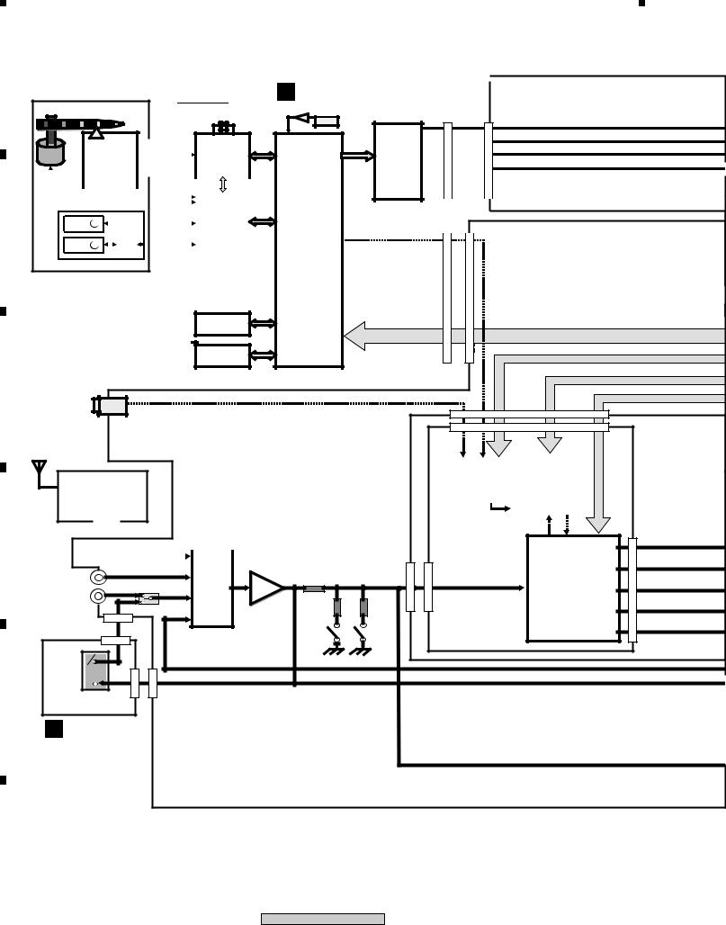
3. BLOCK DIAGRAM AND SCHEMATIC DIAGRAM
3.1 BLOCK DIAGRAM
Traverse Mechanism Assy |
|
|
B DVDM ASSY |
|
|
VWT1199 |
CN101 |
DVD MODULE |
CN903 |
CN8801 |
|
CN1013 |
20MHz |
IC501 |
|||
|
|
|
27MHz |
|
|
|
|
|
|
|
|
03SD PU |
|
|
|
|
|
|
IC301 |
IC601 |
MM1623 |
|
|
|
|
|
|
|
|
|
|||
|
|
|
|
|
|
|
|
|
|
|
|
|
|
|
|
|
|
|
|
|
|||||||
SPINDLE |
|
|
|
|
|
|
|
|
|
|
|
|
|
|
|||||||||||||
|
|
|
|
|
|
|
|
|
|
|
|
|
|
|
|
|
|
|
|||||||||
|
|
|
|
|
|
|
|
|
|
|
|
STM6316ATXXA |
STM5589CVA |
VlDEO AMP |
|
|
|
|
|
|
|
|
|
||||
Motor |
|
|
|
|
|
|
|
|
|
|
|
|
DRlVER |
|
|
|
|
|
|
|
|||||||
|
|
|
|
|
|
|
|
|
|
|
|
|
|
|
|
|
|
|
|
|
|
|
|
|
|||
|
|
|
|
|
|
PlCK UP |
|
|
|
|
|
|
FRONT END IC |
|
6IN-6OUT |
|
|
|
|
|
|
|
|
|
|||
|
|
|
|
|
|
ASSY |
|
|
|
|
|
|
|
BACK END IC |
|
|
|
|
|
|
|
|
|
|
|||
|
|
|
|
|
|
|
|
|
|
|
|
|
|
|
|
|
|
|
|
|
|
|
|
|
|
|
|
|
|
|
|
|
|
|
|
|
|
|
|
|
|
|
|
|
|
|
|
|
|
|
|
|
|
|
|
|
|
|
|
|
|
|
|
|
|
|
|
|
|
|
|
M63018FP |
|
|
|
|
|
|
|
|
|
|
|
|
|
*single disc mecha |
|
|
|
|
|
|
|
CN105 |
|
IC101 |
system control |
|
|
|
|
|
|
|
|
|
|
||||
|
|
|
|
|
|
|
|
|
|
|
|
|
|
|
|
|
|
|
|
|
|||||||
|
|
Steppingtor M |
|
|
|
|
|
|
|
|
|
|
FTS&SPDL DRlVER |
|
|
|
|
|
|
|
|
|
|
||||
|
|
|
|
|
|
|
|
|
|
|
|
|
|
|
|
|
|
|
|
|
|
||||||
+ |
- |
|
|
|
|
|
|
|
|
CN104 |
|
|
MPEG |
|
|
|
|
|
|
|
|
|
|
||||
|
|
|
|
|
|
|
|
|
|
|
|
|
|
|
|
|
|
|
|
|
|
DOUT |
|||||
|
|
|
|
|
|
|
|
|
|
|
|
|
|
|
|
|
|
|
|
|
|
|
|
||||
|
|
|
|
|
|
|
|
|
|
|
|
|
|
|
|
|
|
|
|
|
|
|
|
||||
|
|
LoadMotor |
|
|
|
|
|
|
|
|
|
|
|
|
|
Video Decoder Video |
|
|
|
|
|
|
|
|
|
|
|
+ |
M |
|
|
L |
|
|
|
|
|
|
|
Encoder |
|
|
|
|
|
|
|
|
|
|
|||||
- |
|
|
|
|
|
|
|
|
|
|
|
|
(withPictureControl) |
|
|
|
|
|
|
|
|
|
|
||||
|
|
|
|
|
|
|
|
|
|
|
|
CN103 |
|
|
Video DAC |
|
|
|
|
|
|
|
|
|
|
||
|
|
|
|
|
|
|
|
|
|
|
|
|
|
|
|
|
(Progressive: 54MHz) |
|
CN901 |
|
|
|
|
CN5502 |
|||
|
|
|
|
|
|
|
|
|
|
|
|
|
|
|
|
|
WMA Playback |
|
|
|
|
|
|||||
|
|
|
|
|
|
|
|
|
|
|
|
|
|
|
|
|
Audeo Decoder |
|
|
|
|
|
|
|
|
|
|
|
|
|
|
|
|
|
|
|
|
|
|
|
|
|
|
|
-DD MPEG |
|
|
|
|
|
|
|
|
|
|
|
|
|
|
|
|
|
|
|
|
|
|
|
|
|
|
|
JPEG Viewer |
|
|
|
|
|
|
|
|
|
|
|
|
|
|
|
|
|
|
|
|
|
|
|
|
|
|
|
RW Playback |
|
|
|
|
|
|
|
|
|
|
|
|
|
|
|
|
|
|
|
|
|
|
|
|
|
|
|
(VRmode with CPRM) |
|
|
|
|
|
|
|
|
|
|
IC802
64M SDRAM
IC603
16M FLASH ROM
JA8602
LINE 2 IN (OPT DIGITAL)
|
|
|
|
|
|
|
|
|
|
|
|
|
|
|
|
IC8501 |
||
|
|
|
|
|
|
|
|
|
|
|
|
AK4114 |
|
|||||
|
|
|
|
|
|
|
|
|
|
|
|
|
DSPD56367 |
|||||
|
|
|
|
|
|
|
|
|
|
|
|
IC8201 |
|
|||||
|
|
FM/AM |
|
|
|
|
|
|
||||||||||
|
|
|
|
|
|
|
|
|
|
DSP |
||||||||
|
|
|
|
|
|
DIR |
|
|
|
|||||||||
|
E |
TUNER |
|
|
|
|
|
|
|
|
|
DolbyDigital Decoder |
||||||
|
|
|
|
|
|
|
|
|
Dolby PrologicII |
|||||||||
|
CN201 |
MODULE |
|
|
|
|
|
|
|
|
|
DTS Decoder |
||||||
|
|
|
|
CN5612(1/2) |
CN8007(1/2) |
|
|
|
|
|||||||||
|
|
|
|
|
|
|
|
|
|
|||||||||
|
|
|
|
|
|
|
|
|||||||||||
|
|
|
|
|
|
|
|
|
|
|
|
|
|
|
|
|
||
|
|
|
|
|
|
|
|
|
|
|
|
|
|
|
|
|
||
|
CN5701 |
|
|
|
|
|
|
|
|
C |
|
|
|
|
|
|||
|
|
|
|
|
|
|
|
|
|
|
|
|
|
|
||||
|
|
|
|
|
|
|
|
|
|
|
|
|
|
|
|
|
|
|
|
|
|
|
|
|
|
|
|
|
|
|
DSP ASSY |
|
|
|
|||
|
|
|
|
|
|
|
|
|
|
|
|
|
|
|
||||
|
|
|
|
|
|
|
|
|
|
|
|
|
|
|
|
|
|
|
|
|
ATTENUATOR |
IC8401 |
|
LINE 1 |
|
|
|
|
IC3001 |
|
|
AK4529 |
|
IN |
- 6dB |
- 10dB |
||
INPUT |
BUFFER |
|
8ch |
|
IC3001 |
|
|||
SELECTOR |
IC3003 |
|
||
|
CODEC |
|||
TV IN |
|
|
|
|
TV IN |
|
|
|
|
SELECTOR |
|
|
|
|
CN8301(1/2) |
|
|
|
|
CN801(1/2) |
|
|
|
|
MY/NV MODEL ONLY |
|
|
|
|
TV IN |
|
|
|
|
LINE |
|
|
|
|
OUT |
|
|
|
|
CN801 |
(2/2) |
CN8301(2/2) |
EURO SCART
TERMINAL
L EURO SCART
ASSY (1/2)
CN5620
CN8011
CN8007(2/2)
18
XV-DV515
|
1 |
|
2 |
|
3 |
|
4 |
|
|
|
|
|
|
||||
|
|
|
|
|
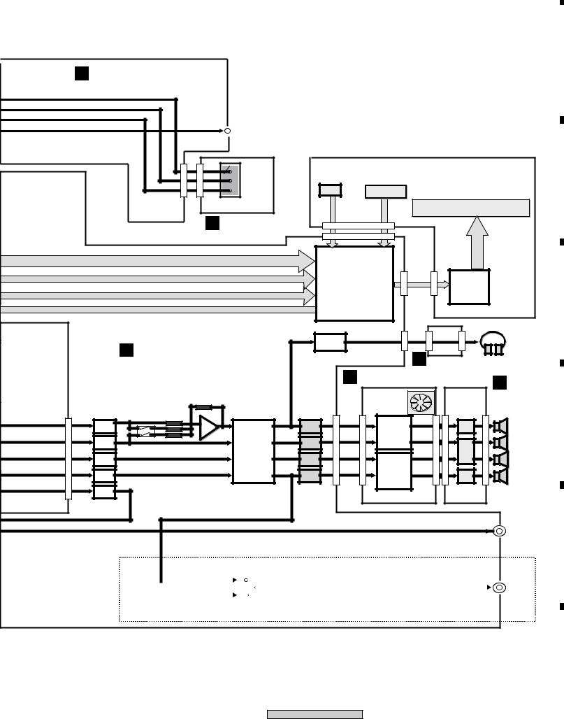
|
5 |
|
6 |
|
7 |
|
8 |
|
|
|
|
J POWER ASSY(1/2)
R/Cr |
|
G/Y |
|
B/Cb |
|
V |
|
CN8803 |
CN101 |
L
COMPOSITE
VIDEO OUT
R/Cr |
M |
|
|
G/Y |
|
|
IR |
B/Cb |
SENSOR |
EURO SCART
TERMINAL
EURO SCART
ASSY (2/2)
CN5611 (1 /2)
IC5501
PDC104A
DISPLAY ASSY
KEY |
V5601 |
FL Tube
CN5601
(1/2)
CN5611 |
(2/2) |
CN5601 |
(2/2) |
|
|
|
micro |
|
|
|
IC5601 |
|
|
|
|
Processoer |
|
|
|
FL |
|
|
|
|
|
|
|
CN5611 |
Driver IC |
|
|
|
|
|
CN3902 |
CN3901 |
(2/2) |
|
|
|
|
IC3901 |
|
|
JA3901 |
|
||
|
|
Headphone |
|
|
|
|
|
|
|
F CONTROL ASSY |
AMP |
|
|
|
|
|
|
|
|
|
|
I |
HP ASSY |
|
||
|
|
|
|
|
HEADPHONE |
|||
|
|
|
|
|
|
|
|
|
|
|
|
D 6CH AMP ASSY |
|
OUT |
|||
CN5612(2/2) |
|
|
|
J |
||||
|
CN3501 |
CN5531 |
|
|
|
|
||
|
MODULE |
|
|
SPEAKER RELAY |
||||
|
|
|
|
|
|
|
POWER |
|
|
|
|
|
POWER AMP |
|
|
|
|
|
|
|
|
|
|
|
|
ASSY(2/2) |
FL/FR |
IC3059 |
ANDREW |
|
|
|
|
|
|
|
|
|
|
|
|
|
||
- |
|
|
IC3301 |
|
|
|
FL/FR |
|
LPF |
|
|
|
|
|
|||
+ |
|
|
STK402270 |
|
|
|
OUT |
|
|
IC3062 |
|
|
|
|
|||
SW |
|
|
|
|
|
|
SW |
|
|
BD3814FV |
|
|
|
|
|
||
LPF |
|
|
|
|
|
|
OUT |
|
|
|
E-VOL |
|
|
|
|
|
|
|
|
|
|
|
|
|
|
|
Center |
|
6ch E-vol |
|
|
|
|
|
CENTRE |
LPF |
|
|
STK402- |
|
|
|
||
|
|
|
|
|
OUT |
|||
|
|
|
|
|
|
|
||
SL/SR |
|
|
|
270 |
|
|
|
|
|
|
|
|
|
|
|
SL/SR |
|
LPF |
|
|
|
3ch Power |
|
|
|
|
|
|
|
|
CN3001 |
|
OUT |
||
REC |
|
|
|
Amp |
|
CN3031 |
||
|
|
|
|
JA3301 |
||||
OUT |
|
IC3056 |
|
|
|
|||
LPF |
|
IC3057 |
|
|
|
|
|
|
|
|
IC3058 |
|
|
|
|
|
|
|
|
|
|
|
|
|
|
JA3001 |
|
|
|
|
|
|
|
|
LINE |
|
|
|
|
|
|
|
|
OUT |
|
WIRE LESS OUT |
XV-DV515 ONLY |
||||||
|
SELECT |
|||||||
|
|
|
|
|
|
|
JA9091 |
|
|
|
|
|
|
|
|
||
|
|
|
|
|
|
|
|
WIRE LESS |
|
|
|
|
|
|
|
|
OUT |
|
|
|
|
|
|
|
|
|
|
|
|
|
|
|
|
|
|
|
|
|
|
|
|
|
|
|
|
|
|
IC9091 |
|
|
|||
19
XV-DV515
A
B
C
D
E
F
|
5 |
|
6 |
|
7 |
|
8 |
|
|
|
|
|
|
||||
|
|
|
|
|
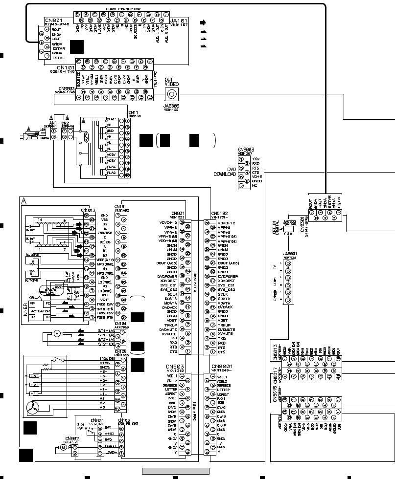
|
1 |
|
2 |
|
3 |
|
4 |
|
|
|
|
|
|
3.2 LOAB ASSY and OVERALL WIRING DIAGRAM
A
L EURO SCART ASSY (XWZ3724)
(RF)
: RF SIGNAL ROUTE
(F): FOCUS SERVO LOOP LINE
(T): TRACKING SERVO LOOP LINE
(S) : STEPPING SERVO LOOP LINE
B
|
T1 |
|
|
POWER TRANSFORMER |
|
|
XTS3066 |
|
POWER CORD |
J J 1/2, J 2/2 |
|
: ADG1154 (MY) |
POWER ASSY |
|
: ADG1156 (NV) |
||
|
(XWZ3716)
C |
|
|
|
|
|
|
DVD ASSY (AXA7121) |
|
|
||
|
PICKUP ASSY-S (OXX8005) |
|
|
||
|
|
(RF) |
|
|
|
|
|
(RF) |
|
|
|
|
|
(RF) |
|
|
|
|
|
(RF) |
|
|
|
|
|
(RF) |
|
|
|
|
|
(RF) |
|
|
|
D |
|
|
3/3B (AWM7808) |
|
|
|
|
(T) |
|
||
|
|
|
|
|
|
|
|
(T) |
|
|
|
|
|
(F) |
|
|
|
|
|
(F) |
1/3BB- |
ASSYDVDM |
|
|
STEPPING |
|
|||
|
(S) |
|
|
||
|
MOTOR |
|
(S) |
|
|
|
: VXM1101 |
(S) |
|
|
|
|
|
|
(S) |
|
|
E |
SPINDLE MOTOR |
|
|
|
|
: VXM1099 |
|
|
|
||
|
A (VWG2279) |
|
|
CN8003 |
|
|
|
LOAB ASSY |
|
|
|
F |
|
|
|
|
|
|
A |
LOADING MOTOR |
|
|
|
|
ASSY : VXX2505 |
|
|
|
|
|
20 |
|
|
XV-DV515 |
|
|
|
|
|
|
|
|
|
1 |
2 |
3 |
4 |

|
5 |
|
6 |
|
7 |
|
8 |
|
|
|
|
|
|
Note : When ordering service parts, be sure to refer to "EXPLODED VIEWS and PARTS LIST" or "PCB PARTS LIST".
A
AMP MODULE 6CH (AXQ7242)
D |
6CH AMP (AZW7283) |
CN3651 |
K |
TRADE 1 ASSY (XWZ3725) |
|
|
|
|
|
|
|
|
B |
|
|
|
|
|
XKE3021 |
|
|
|
|
|
|
|
|
|
C |
|
H TRADE 2 ASSY (XWX3071) |
|
|
|
|
|
|
|
|
|
|
|
CN201 |
|
|
|
|
|
|
|
52044-1315 |
|
|
|
|
|
|
|
E |
|
|
|
|
|
|
|
FM/AM TUNER |
D |
|
|
|
|
|
|
MODULE |
|
|
|
|
|
|
|
(AXQ7229) |
|
|
F |
F 1/4- F 4/4 |
|
|
|
|
PHONES |
|
CONTROL ASSY (XWZ3710 : XV-DV515) |
|
|
I |
|
|||
|
(XWZ3703 : XV-DV313) |
|
|
|
|
||
|
|
|
|
|
|
|
|
|
|
|
|
|
HP ASSY |
|
|
|
|
|
|
|
(XWZ3715) |
|
|
|
|
|
|
|
|
|
E |
G TRADE 3 ASSY (XWZ3714) |
|
|
|
M |
|
|
|
|
|
|
DISPLAY ASSY |
|
|||
|
|
|
|
|
(XWZ3720) |
|
|
CN8007 |
|
|
CN8011 |
LED ASSY |
|
|
F |
|
|
|
|
|
|
||
C |
C 1/2, C 2/2 |
|
|
N (XWZ3721) |
|
|
|
|
|
|
|
|
|||
|
|
|
|
|
|
||
DSP ASSY (AWX8253) |
|
|
|
|
|
|
|
|
|
XV-DV515 |
|
|
|
21 |
|
|
5 |
|
7 |
8 |
|
|
|
|
6 |
|
|
|
|||
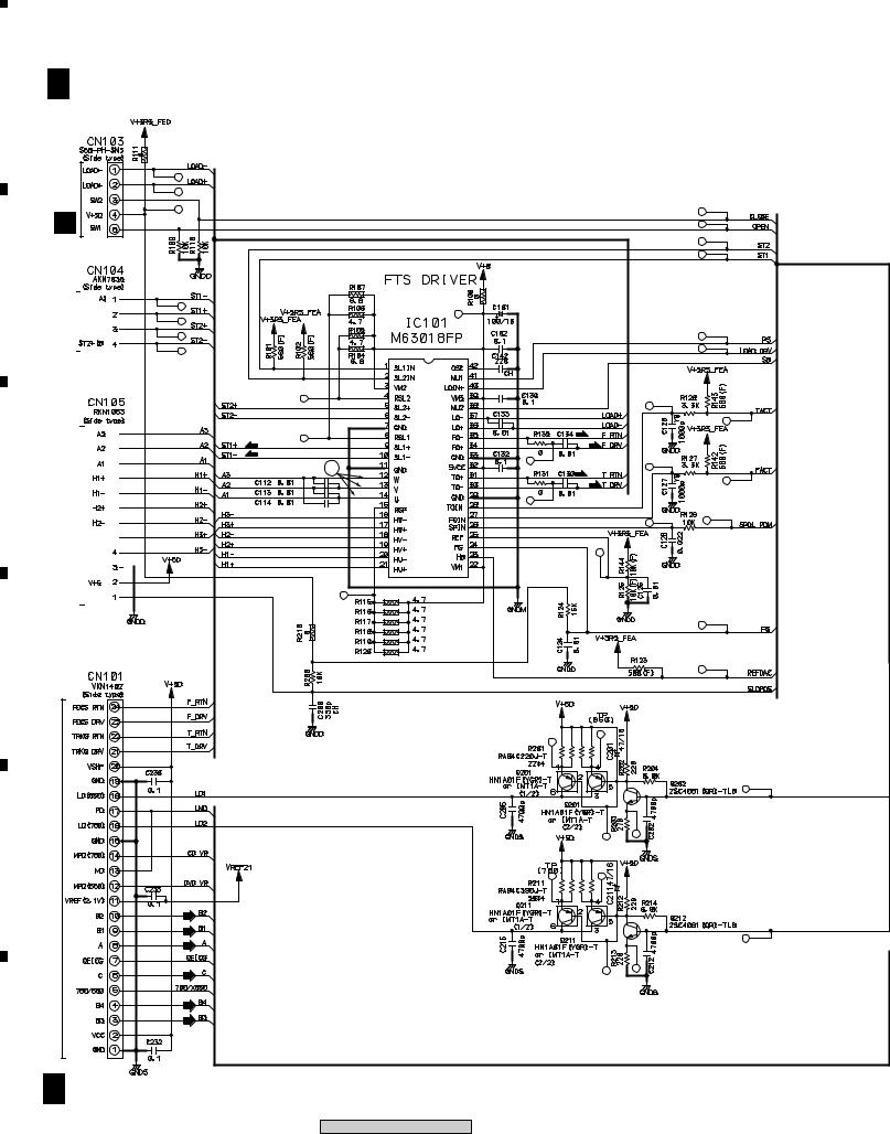
A
B
C
1 |
|
2 |
|
3 |
|
4 |
|
|
|
|
|
3.3 DVDM ASSY(1/3)
B 1/3 DVDM ASSY (AWM7808)
STEPPING
A CN601
MOTOR


SPINDLE MOTOR

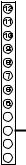
(S)
(S)
(S)
(S)
 (S)
(S)
 (S)
(S)
(S) |
(F) |
(F) |
|
(S) |
|
3 |
(T) |
|
(T) |
D
E
F
(F)
 (F)
(F)
(T)
 (T)
(T)
PICKUP ASSY CN1013
B 1/3
22
XV-DV515
|
1 |
|
2 |
|
3 |
|
4 |
|
|
|
|
|
|
||||
|
|
|
|
|
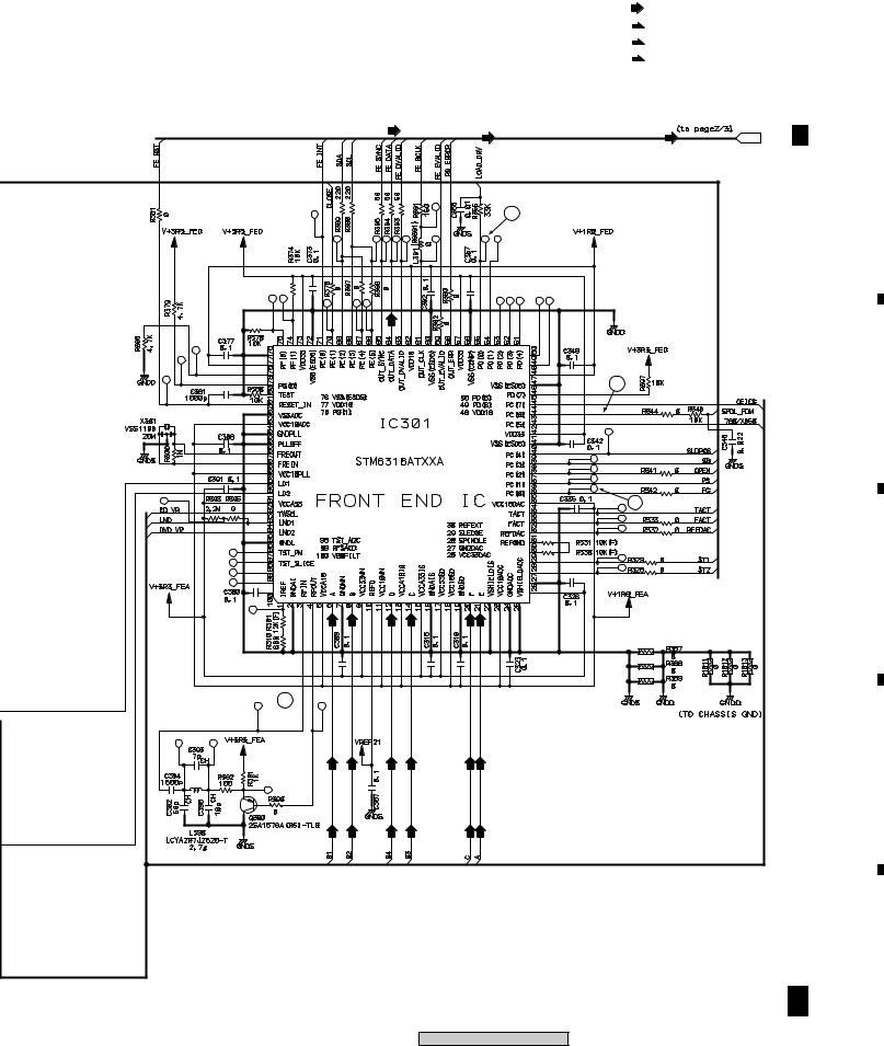
|
5 |
|
6 |
|
7 |
|
8 |
|
|
|
|
|
|
|
: FE DATA SIGNAL ROUTE |
A |
(F) |
|
|
: FOCUS SERVO LOOP LINE |
|
|
(T) |
: TRACKING SERVO LOOP LINE |
|
(S) |
: STEPPING SERVO LOOP LINE |
|
|
|
|
|
|
|
 B 2/3
B 2/3
B
4
5
C
2
D
1 
E
F
B 1/3
23
XV-DV515
|
5 |
|
6 |
|
7 |
|
8 |
|
|
|
|
|
|
||||
|
|
|
|
|
1 |
2 |
|
|
|
3 |
4 |
3.4 DVDM ASSY(2/3) |
|
|
|
|
|
|
A |
B 2/3 DVDM ASSY (AWM7808) |
|||||
|
||||||
B |
|
|
|
|
|
|
C |
|
|
|
|
|
(D) |
|
|
|
|
|
|
|
D |
|
|
|
|
|
|
|
|
|
|
|
|
(D) |
E |
|
|
|
|
|
|
|
|
|
|
|
|
(D) |
|
(PB/B) |
(CY/G) |
(PR/R) |
(Y) |
(C) |
(C/V) |
F |
|
|
|
|
|
|
B 2/3 |
|
|
|
|
|
|
24 |
XV-DV515 |
|
|
|
|
|
|
|
|
|
|
|
|
1 |
2 |
|
|
|
3 |
4 |
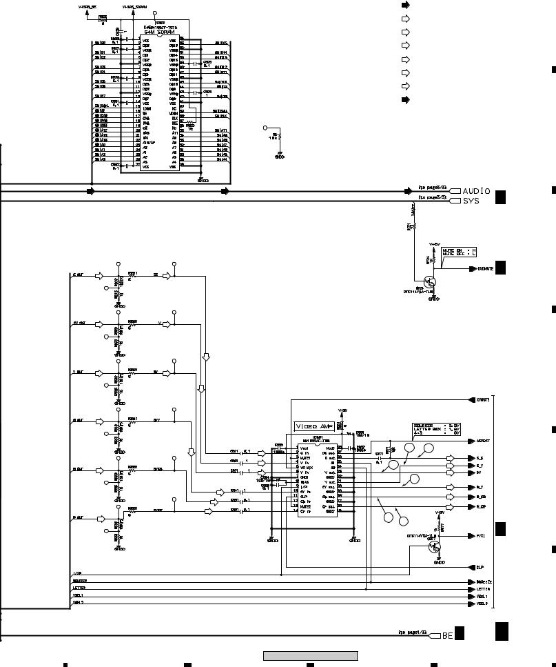
|
5 |
|
6 |
|
7 |
|
8 |
|
|
|
|
|
|
|
|
|
|
: FE DATA SIGNAL ROUTE |
A |
|
|
|
|
(C/V) |
|
||
|
|
|
|
|
||
|
|
|
|
: VIDEO SIGNAL ROUTE (C/V) |
||
|
|
|
|
(Y) |
|
|
|
|
|
|
: S VIDEO SIGNAL ROUTE (Y) |
||
|
|
|
|
(C) |
|
|
|
|
|
|
: S VIDEO SIGNAL ROUTE (Y) |
||
|
|
|
(PR/R) |
|
|
|
|
|
|
|
: VIDEO SIGNAL ROUTE (PR/R) |
||
|
|
|
(CY/G) |
|
|
|
|
|
|
|
: VIDEO SIGNAL ROUTE (CY/G) |
||
|
|
|
(PB/B) |
|
|
|
|
|
|
|
: VIDEO SIGNAL ROUTE (PB/B) |
||
|
|
|
|
(D) |
|
|
|
|
|
|
: AUDIO SIGNAL ROUTE (DIGITAL) |
||
|
|
|
|
|
|
B |
(D) |
|
(D) |
|
(D) |
|
B 3/3 |
|
|
|
|
|
|
|
|
|
|
|
|
|
C |
(C) |
(C) |
|
|
|
|
B 3/3 |
(C/V) |
(C/V) |
|
|
|
|
|
|
|
(C) |
|
|
|
|
(Y) |
(Y) |
(C/V) |
|
|
|
D |
|
|
|
|
|
|
|
(CY/G) |
|
|
|
|
|
|
|
(Y) |
(C) |
|
7 |
8 |
|
|
|
|
|
|||
|
|
(C/V) |
|
|
(C) |
|
|
|
6 |
(Y) |
|
||
(PB/B) |
|
|
|
|||
|
(Y) |
(C/V) |
|
|||
|
|
|
|
|
||
|
|
|
|
|
9 |
|
|
|
(CY/G) |
|
|
(CY/G) |
E |
|
|
|
|
|
||
|
|
(PB/B) |
|
|
(PB/B) |
|
|
|
|
|
|
||
|
|
|
|
|
|
|
|
|
(PR/R) |
|
|
(PR/R) |
|
|
|
|
|
|
|
|
(PR/R) |
|
|
10 |
11 |
|
|
|
|
|
|
B 3/3 |
||
|
|
|
|
|
|
|
|
|
|
|
|
|
F |
|
|
|
|
|
B 1/3 |
B 2/3 |
|
|
|
XV-DV515 |
|
|
25 |
|
|
|
|
|
|
|
5 |
|
6 |
7 |
|
|
8 |
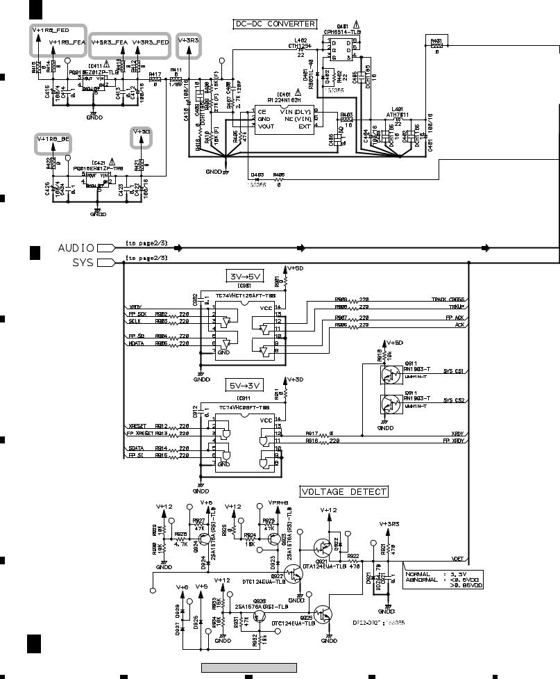
|
1 |
|
2 |
|
3 |
|
4 |
|
|
|
|
|
|
3.5 DVDM ASSY(3/3)
B 3/3 DVDM ASSY (AWM7808)
A
1.8V Reg.
B
1.8V Reg.
|
B 2/3 |
(D) |
(D) |
(D) |
C |
|
|
|
|
D |
|
|
|
|
E |
|
|
|
|
F |
|
|
|
|
|
B 3/3 |
|
|
|
|
26 |
|
XV-DV515 |
|
|
|
|
|
|
|
1 |
2 |
3 |
4 |
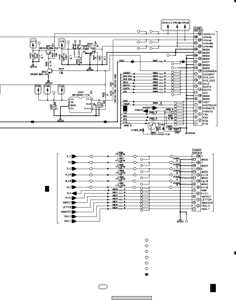
|
5 |
|
6 |
|
7 |
|
|
|
|
|
|
(D) |
(D) |
|
5V Reg. |
|
|
B 2/3 |
|
(D) |
(D) |
|
(Y) |
(Y) |
(Y) |
(C/V) |
(C/V) |
(C/V) |
(C) |
(C) |
(C) |
(PR/R) |
(PR/R) |
(PR/R) |
(PB/B) |
(PB/B) |
(PB/B) |
(CY/G) |
(CY/G) |
(CY/G) |
B 2/3
(C/V)
: VIDEO SIGNAL ROUTE (C/V)
(Y)
: S VIDEO SIGNAL ROUTE (Y)
(C)
: S VIDEO SIGNAL ROUTE (Y)
(PR/R)
: VIDEO SIGNAL ROUTE (PR/R)
(CY/G)
: VIDEO SIGNAL ROUTE (CY/G)
(PB/B)
: VIDEO SIGNAL ROUTE (PB/B)
(D)
: AUDIO SIGNAL ROUTE (DIGITAL)
: The power supply is shown with the marked box.
XV-DV515
8
A
CN5102 |
|
|
B |
||
1/2 |
|
|
|
|
|
J |
|
|
|
|
|
|
|
|
C
2/2CN8801 |
|
|
|
D |
|||
|
|||
|
|
|
|
J |
|
|
|
|
|
|
|
|
|
|
|
E
F
B 3/3
27
|
5 |
|
6 |
|
7 |
|
8 |
|
|
|
|
|
|
||||
|
|
|
|
|
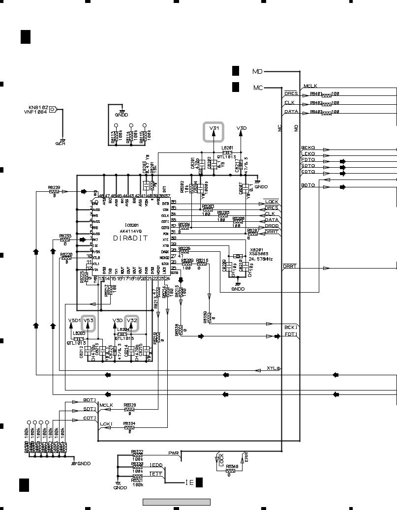
|
1 |
2 |
3 |
4 |
|
3.6 DSP ASSY(1/2) |
|
|
|
A |
C 1/2 DSP ASSY (AWX8253) |
|
|
|
|
|
|
C 2/2 |
|
|
|
|
C 2/2 |
|
B |
|
|
|
|
|
|
|
|
(AD) |
|
|
|
|
(AD) |
|
|
|
|
(AD) |
|
|
|
|
(AD) |
|
|
(D) |
|
|
C |
|
|
|
|
|
|
(D) |
|
|
|
(D) |
(D) |
|
|
|
|
|
(D) |
|
D |
|
|
|
|
|
(D) |
(D) |
(D) |
(D) |
|
|
|
||
|
|
(D) |
(D) |
(D) |
E |
|
|
|
|
|
|
(D) |
(D) |
(D) |
F |
|
|
|
|
|
C 1/2 |
|
C 2/2 |
|
|
28 |
|
XV-DV515 |
|
|
|
|
|
|
|
1 |
2 |
3 |
4 |
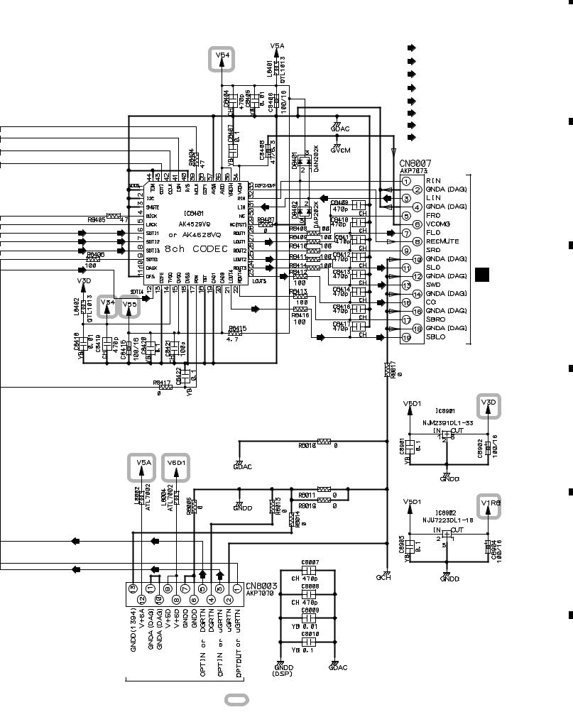
|
5 |
|
6 |
|
|
|
|
(AD) |
(AD) |
|
(AD) |
(AD) |
(FL) |
(AD) |
(AD) |
|
|
|
(SL) |
(AD) |
|
|
|
|
(SW) |
|
|
(C) |
|
|
(AD) |
|
|
(DVD) |
7 |
|
8 |
|
: AUDIO SIGNAL ROUTE (L ch)
(DVD)
: AUDIO SIGNAL ROUTE (DVD Lch)
(D)
: AUDIO SIGNAL ROUTE (DIGITAL)
(AD)
: AUDIO DATA SIGNAL ROUTE
(FL)
: AUDIO SIGNAL ROUTE (Front L ch)
(SL)
: AUDIO SIGNAL ROUTE (Surround L ch)
(C)
: AUDIO SIGNAL ROUTE (Center ch)
(SW)
: AUDIO SIGNAL ROUTE (Sub Woofer ch)
(FL) |
CN5614 |
(SL) |
(SW) |
G |
|
|
(C) |
|
(DVD) |
(DVD) |
A
B
C
(D) |
(D) |
(D) |
(D) |
3.3V Reg.
D
1.8V Reg.
E
(D) |
(D) |
F
G |
CN5615 |
|
|
|||
C |
1/2 |
|||||
|
: The power supply is shown with the marked box. |
|||||
|
|
|
||||
|
|
|
|
|
|
|
|
|
|
|
29 |
||
|
|
XV-DV515 |
|
|||
|
|
|
|
|
||
|
5 |
|
6 |
|
7 |
|
8 |
|
|
|
|
|
|
||||
|
|
|
|
|
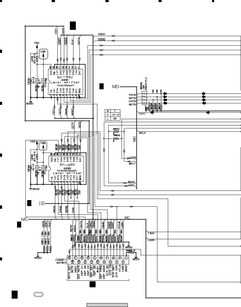
1 |
2 |
3 |
4 |
3.7 DSP ASSY(2/2) |
|
|
|
A |
C 2/2 DSP ASSY (AWX8253) |
|
|
|
|
||
B |
|
|
|
|
|
C 1/2 |
|
|
|
(AD) |
(AD) |
|
|
(AD) |
(AD) |
|
|
(AD) |
(AD) |
|
|
(AD) |
(AD) |
|
|
(D) |
(D) |
C |
|
|
|
D |
|
|
|
C 1/2 |
|
|
|
C 1/2 |
|
|
|
E
F |
G CN5618 |
C 2/2 |
: The power supply is shown with the marked box. |
|
30
XV-DV515
|
1 |
|
2 |
|
3 |
|
4 |
|
|
|
|
|
|
||||
|
|
|
|
|
 Loading...