


DVD AV RECEIVER
RADIO AV CON DVD
AUTORADIO AV LECTEUR DE DVD
AVH-P5200DVD
AVH-P5200BT
Español Français English
Installation Manual Manual de instalación Manuel d’installation

Contents |
|
Connecting the units ........................... |
2 |
Connecting the power cord ............................... |
4 |
When connecting to |
|
separately sold power amp ...................... |
6 |
When connecting |
|
with a rear view camera ........................... |
7 |
When connecting the external |
|
video component and the display ........... |
8 |
When using a display connected to |
|
rear video output ........................................... |
8 |
Connecting the system ....................................... |
8 |
Installation ............................................. |
9 |
DIN front/rear-mount ..................................... |
9 |
DIN Front-mount ..................................................... |
9 |
DIN Rear-mount .................................................... |
10 |
Removing the unit ................................................ |
10 |
Fastening the front panel .............................. |
10 |
Installing the microphone |
|
(AVH-P5200BT only) ................................. |
11 |
When installing the microphone |
|
on the sun visor ........................................... |
11 |
When installing the microphone |
|
on the steering column .............................. |
11 |
Adjusting the microphone angle .................. |
11 |
Connecting the units
 WARNING
•To avoid the risk of accident and the potential violation of applicable laws, the front DVD (sold separately) feature should never be used while the vehicle is being driven. Also, rear displays should not be in a location where it is a visible distraction to the driver.
•In some countries or states the viewing of images on a display inside a vehicle even by persons other than the driver may be illegal. Where such regulations apply, they must be obeyed and this unit’s DVD features should not be used.
 CAUTION
•PIONEER does not recommend that you install or service your display yourself. Installing or servicing the product may expose you to risk of electric shock or other hazards. Refer all installation and servicing of your display to authorized Pioneer service personnel.
•Secure all wiring with cable clamps or electrical tape. Do not allow any bare wiring to remain exposed.
•Do not drill a hole into the engine compartment to connect the yellow lead of the unit to the vehicle battery. Engine vibration may eventually cause the
insulation to fail at the point where the wire passes from the passenger compartment into the engine compartment. Take extra care in securing the wire at this point.
•It is extremely dangerous to allow the display lead to become wound around the steering column or gearshift. Be sure to install the display in such a way that it will not obstruct driving.
•Make sure that wires will not interfere with moving parts of the vehicle, such as the gearshift, parking brake or seat sliding mechanism.
•Do not shorten any leads. If you do, the protection circuit may fail to work properly.
 WARNING
LIGHT GREEN LEAD AT POWER CONNECTOR IS DESIGNED TO DETECT PARKED STATUS AND MUST BE CONNECTED TO THE POWER
SUPPLY SIDE OF THE PARKING BRAKE SWITCH. IMPROPER CONNECTION OR USE OF THIS LEAD MAY VIOLATE APPLICABLE LAW AND MAY RESULT IN SERIOUS INJURY OR DAMAGE.
2
Connecting the units
 WARNING
•Use speakers over 50 W (output value) and between 4 Ω to 8 Ω (impedance value). Do not use 1 Ω to 3 Ω speakers for this unit.
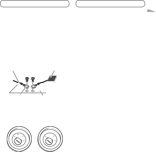
•The black cable is ground. When installing this unit or power amp (sold separately), make sure to connect the ground wire first. Ensure that the ground wire is properly connected to metal parts of the car’s body. The ground wire of the power amp and the one of this unit or any other device must be connected to the car separately
with different screws. If the screw for the ground wire loosens or falls out, it could result in fire, generation of smoke or malfunction.
Ground wire |
POWER AMP |
||
|
|
|
|
|
|
|
|
Other devices |
Metal parts of car’s body |
|
(Another electronic |
||
|
||
device in the car) |
|
 Important
•This unit cannot be installed in a vehicle without ACC (accessory) position on the ignition switch.
|
|
CC |
|
|
|
|
|
|
|
|
|
F |
A |
O |
|
|
|
F |
O |
|
|
|
|
N |
|
N |
||||||
O |
F |
|
|
|
|
O |
F |
|
|
|
|
|
|
|
S |
|
|
|
S |
||
|
|
|
|
|
|
|
|
|
||
|
|
|
|
|
T |
|
|
|
|
T |
|
|
|
|
R |
A |
|
|
|
R |
A |
|
|
|
T |
|
|
|
T |
|
||
ACC position |
No ACC position |
|||||||||
•Use of this unit in conditions other than the following could result in fire or malfunction.
—Vehicles with a 12-volt battery and negative grounding.
—Speakers with 50 W (output value) and 4 ohm to 8 ohm (impedance value).
•To prevent short-circuit, overheating or malfunction, be sure to follow the directions below.
—Disconnect the negative terminal of the battery before installation.
—Secure the wiring with cable clamps or adhesive tape. Wrap adhesive tape around wiring that comes into contact with metal
parts to protect the wiring.
—Place all cables away from moving parts, such as gear shift and seat rails.
—Place all cables away from hot places, such as near the heater outlet.
—Do not connect the yellow cable to the battery by passing it through the hole to the engine compartment.
—Cover any disconnected cable connectors with insulating tape.
—Do not remove RCA caps if RCA cables are not used.
—Do not shorten any cables.
—Never cut the insulation of the power cable of this unit in order to share the power with other devices. The current capacity of the cable is limited.
—Use a fuse of the rating prescribed.
—Never wire the speaker negative cable directly to ground.
—Never band together negative cables of multiple speakers.
•When this unit is on, control signals are sent through the blue/white cable. Connect this cable to the system remote control of an external power amp or the vehicle’s auto-antenna relay control terminal (max. 300 mA 12 V DC). If the vehicle is equipped with a glass antenna, connect it to the antenna booster power supply terminal.
•Never connect the blue/white cable to the power terminal of an external power amp. Also, never connect it to the power terminal of the auto antenna. Doing so may result in battery drain or a malfunction.
•IP-BUS connectors are color-coded. Be sure to connect connectors of the same color.
•The black cable is ground. Ground cables for this unit and other equipment (especially, highcurrent products such as power amps) must be wired separately. If they are not, an accidental detachment may result in a fire or malfunction.
English
3
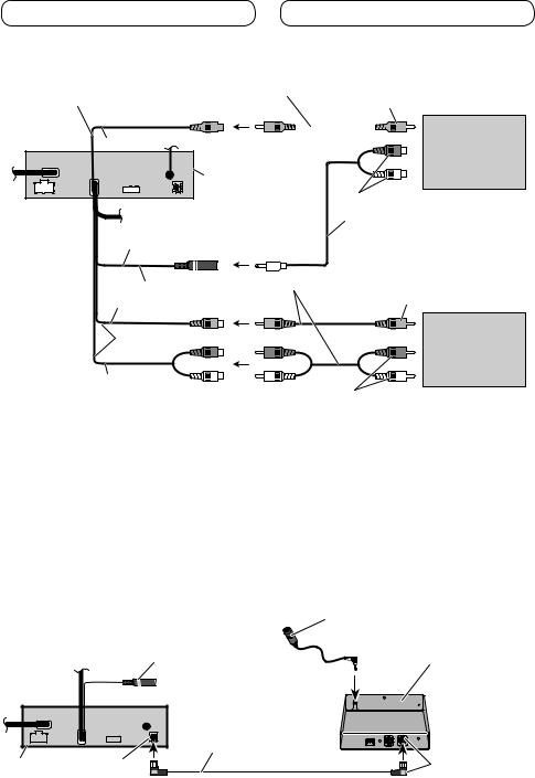
Connecting the units
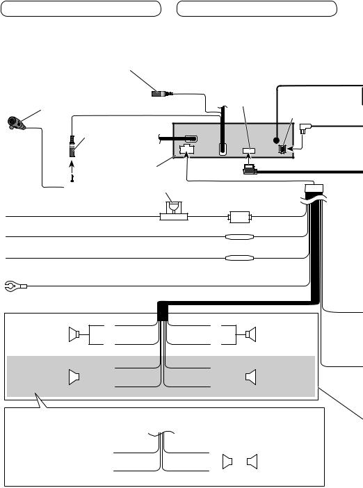
Connecting the power cord
Wired remote input (WIRED REMOTE INPUT) Hard-wired remote control adaptor can be connected (sold separately).
|
|
17 cm (6-3/4 in.) |
|
Microphone (supplied) |
|
RGB input |
|
(AVH-P5200BT only) |
17 cm (6-3/4 in.) |
IP-BUS input |
|
|
|
||
|
|
|
(Blue) |
Microphone input Jack (MIC) |
|
|
|
(AVH-5200BT only) |
|
|
|
This product
 Fuse (10 A) 4 m (13 ft. 1 in.)
Yellow
Connect to the constant 12 V supply terminal.
Orange/white
Connect to lighting switch terminal.
Red
Connect to terminal controlled by ignition switch (12 V DC).
Black (chassis ground)
Connect to a clean, paint-free metal location.
|
White |
Gray |
Front speaker |
|
|
|
|
|
|
|
|
Left |
White/black |
Gray/black |
Green Violet
Fuse resistor
Fuse resistor
Front speaker
Right
Rear speaker or |
|
|
|
|
|
|
Rear speaker or |
Subwoofer (4 Ω) |
|
|
|
|
|
|
Subwoofer (4 Ω) |
|
|
|
|
|
|
||
|
|
|
|
|
|
||
|
|
|
Green/black |
Violet/black |
|
||
When using a subwoofer of 70 W (2 Ω), be sure to connect with Violet and Violet/black leads of this unit. Do not connect anything to Green and Green/black leads.
Green |
Violet |
|
||||
Not used. |
|
|
|
|
|
Subwoofer (4 Ω) |
|
|
|
|
|
||
|
|
|
|
|
× 2 |
|
|
|
|
|
|
|
|
Green/black |
Violet/black |
|
||||
|
|
|
|
|
|
|
4
Connecting the units
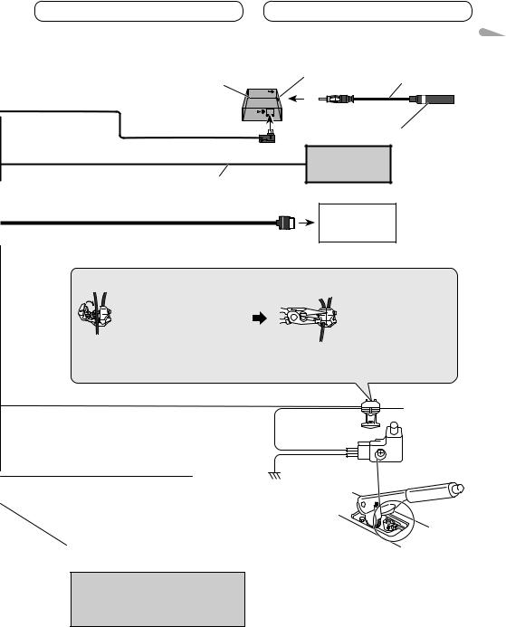
Tuner box (supplied)
80 cm (2 ft. 7 in.)
IP-BUS cable
26 pin cable (Supplied with Navigation unit)
Insert the 26 pin cable in the direction indicated in the figure.
Connection method
1. Clamp the lead.
Note:
Antenna input 80 cm (2 ft. 7 in.)
Antenna cable (supplied)
Pioneer IP-BUS accessories
Navigation unit (AVIC-U220 (sold separately)).
Please contact your dealer to inquire about the connectable navigation unit.
2. Clamp firmly with needle-nosed pliers.
·The position of the parking brake switch depends on the vehicle model. For details, consult the vehicle Owner’s Manual or dealer.
Light green
Used to detect the ON/OFF status of the parking
brake. This lead must be connected to the power Power supply side supply side of the parking brake switch.
Ground side
Blue/white
Connect to system control terminal of the power amp or auto-antenna relay control terminal (max. 300 mA 12 V DC).
With a 2 speaker system, do not connect anything to the speaker leads that are not connected to speakers.
Note:
·Change the initial setting of this unit (refer to the Operation Manual). The subwoofer output of this unit is monaural.
 Parking brake switch
English
5

Connecting the units
When connecting to separately sold power amp
Rear output (REAR OUTPUT)
13 cm (5-1/8 in.) |
|
To rear output |
|
Front output |
13 cm (5-1/8 in.) |
|
|
|
|
|
|
(FRONT OUTPUT) |
|
|
|
|
|
To front output |
|
Subwoofer output |
|
|
|
(SUBWOOFER OUTPUT) |
|
|
|
17 cm (6-3/4 in.) |
|
To subwoofer |
Power amp |
|
|
output |
(sold separately) |
|
|
|
Power amp |
|
|
Connect with RCA cables |
(sold separately) |
|
|
(sold separately) |
|
This product |
|
Power amp |
|
|
(sold separately) |
||
|
|
|
|
Blue/white |
|
|
|
Connect to system control |
|
|
|
terminal of the power amp |
|
|
|
(max. 300 mA 12 V DC). |
|
|
|
|
|
System remote control |
|
|
|
Left |
Right |
|
|
|
|
Subwoofer |
Subwoofer |
|
|
|
|
|
|
|
Front speaker |
Front speaker |
|
|
|
|
|
|
|
Rear speaker |
Rear speaker |
Perform these connections when |
|
|
|
|
|
using the optional amplifier. |
|
|
6
Connecting the units
When connecting with a rear view camera
When this product is used with a rear view camera, it is possible to automatically switch from the video to rear view image when the gear shift is moved to REVERSE (R).
 WARNING
USE INPUT ONLY FOR REVERSE OR MIRROR IMAGE REAR VIEW CAMERA. OTHER USE MAY RESULT IN INJURY OR DAMAGE.
 CAUTION
•The screen image may appear reversed.
•The rear view camera function is to be used as an aid for backing into a tight parking spot. Do not use this function for entertainment purposes.
•Objects in the rear view may appear closer or more distant than they actually are.
This product |
CAUTION |
You must use a camera which outputs mirror reversed images.
RCA cable (sold separately)
13 cm (5-1/8 in.)
To video output
Rear view camera (sold separately)
Rear view camera input (REAR VIEW CAMERA IN)
|
15 cm (5-7/8 in.) |
Fuse resistor |
|
|
|
Violet/white
Of the two lead wires connected to the back lamp, connect the one in which the voltage changes when the gear shift is in the REVERSE (R) position. This connection enables the unit to
sense whether the car is moving forwards or backwards.
• It is necessary to set Camera Polarity properly in System Menu when connecting the rear view camera.
English
7
Connecting the units
When connecting the external video component and the display
Rear monitor output |
RCA cables (sold separately) |
|||||||||||||||||
(REAR MONITOR OUTPUT) |
|
|
|
|
|
|
|
|
|
|
|
|
To video input |
|||||
|
|
|
|
|
|
|
|
|
|
|
|
|
||||||
|
|
|
|
|
|
|
|
|
|
|
|
|
|
|
|
|
|
|
13 cm (5-1/8 in.)
This product
To audio input
Mini pin plug cable Rear audio output (sold separately) (REAR MONITOR OUTPUT(AUDIO))
Display with RCA input jacks (sold separately)
17 cm (6-3/4 in.) |
RCA cables (sold separately) |
|
|
||
Video input (VIDEO INPUT) |
To video output |
|
13 cm (5-1/8 in.) |
External video |
|
component (sold |
||
|
||
|
separately) |
|
Audio input |
|
|
(AUDIO INPUT) |
To audio outputs |
•It is necessary to change AV Input in System Menu when connecting the external video component.
When using a display connected to rear video output
This product’s rear video output and rear audio output are for connection of a display to enable passengers in the rear seats to watch the DVD, etc.
 WARNING
Never install the display in a location where it is visible to the driver while driving.
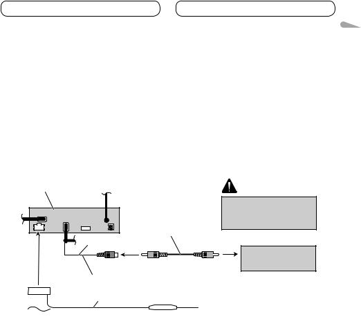
Connecting the system
Wired remote input (WIRED REMOTE INPUT) Hard-wired remote control adaptor can be connected (sold separately).
Microphone
for hands-free phoning
(supplied with Bluetooth adapter)
Bluetooth adapter (e.g. CD-BTB200) (sold separately)
(AVH-P5200DVD only)
IP-BUS cable
(Supplied with Bluetooth adapter)
This product IP-BUS input |
Black |
8
Installation
 Note
Note
•Check all connections and systems before final installation.
•Do not use unauthorized parts. The use of unauthorized parts may cause malfunctions.
•Consult with your dealer if installation requires drilling of holes or other modifications of the vehicle.
•Do not install this unit where:
—it may interfere with operation of the vehicle.
—it may cause injury to a passenger as a result of a sudden stop.
•Do not install the display where it may (i) obstruct the driver’s vision, (ii) impair the performance of any of the vehicle’s operating systems or safety features, including air bags, hazard lamp buttons or (iii) impair the driver’s ability to safely operate the vehicle.
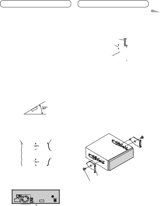
•The semiconductor laser will be damaged if it overheats. Install this unit away from hot places such as near the heater outlet.
•Optimum performance is obtained when the unit is installed at an angle of less than 30°.
•When installing, to ensure proper heat dispersal when using this unit, make sure you leave ample space behind the rear panel and wrap any loose cables so they are not blocking the vents.
Leave ample space |
|
Dashboard |
|||||
|
|
|
|
|
|
|
|
|
|
|
|
|
|
|
|
|
|
|
|
|
|
|
|
|
|
|
|
|
|
|
|
|
|
|
|
|
|
|
|
|
|
|
|
|
|
|
|
|
|
|
|
|
|
|
|
|
|
|
|
|
|
|
|
|
|
|
|
|
|
|
|
|
|
|
|
|
|
|
|
|
|
|
|
|
|
|
|
|
|
|
|
|
|
|
|
•The cords must not cover up the area shown in the figure below. This is necessary to allow the amplifires to radiate freely.
Do not cover this area.
• Make sure you leave enough gap between the |
English |
||||||||
contacting with the dashboard. |
|||||||||
dashboard and the LCD panel of this unit so the |
|
||||||||
LCD panel can be opened and closed without |
|
||||||||
Dashboard |
|
||||||||
Leave gap |
|
|
|
||||||
|
|
||||||||
|
|
|
|
|
|
|
|
|
|
|
|
|
|
|
|
|
|
|
|
LCD panel |
|
|
|
|
|
|
|||
|
|
|
|
|
|
||||
|
|
|
|
|
|
|
|
|
|
DIN front/rear-mount
This unit can be properly installed either from “Front” (conventional DIN Front-mount) or “Rear” (DIN Rear-mount installation, utilizing threaded screw holes at the sides of unit chassis). For details, refer to the following installation methods.
•Use commercially available parts when installing.
DIN Front-mount
1.Decide the position of the side brackets.
•When installing in a shallow space, change the position of side brackets (small).
Side bracket (small)
Flush surface screw (5 mm × 6 mm)
9
Installation
2. Install the unit into the dashboard.
Insert the mounting sleeve into the dashboard. And then secure the mounting sleeve by using a screwdriver to bend the metal tabs (90°) into place.
Dashboard
182
53
Mounting sleeve
Side bracket 


Screw (2 mm × 3 mm)
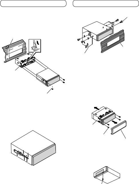
DIN Rear-mount
1.Determine the appropriate position where the holes on the bracket and the side of the unit match.
•When installing in a shallow space, use the following screw holes.
*1 Use binding screws (4 mm × 3 mm) only.
*1
*1
2. Tighten two screws on each side.
Use any of binding screws (4 mm × 3 mm), binding screws (5 mm × 6 mm) or flush surface screws (5 mm × 6 mm), depending on the shape of screw holes in the bracket.
Screw
Dashboard or Console
Factory radio mounting bracket
Removing the unit
Extend top and bottom of the trim ring outwards to remove the trim ring. And then loosen the screws (2 mm × 3 mm) to remove the mounting sleeve.
•When reattaching the trim ring, push the trim ring onto the unit until it clicks after reattaching the mounting sleeve. (If the trim ring is attached upside down, the trim ring will not fit properly.)
Mounting sleeve
Screw (2 mm × 3 mm)
Trim ring
Fastening the front panel
If you do not plan to detach the front panel, the front panel can be fastened with supplied screw.
Screw
10
 Loading...