


DVD AV RECEIVER
AUTORADIO AV LECTEUR DE DVD RADIO AV CON DVD
AVH-P4200DVD
AVH-P3200DVD AVH-P3200BT
Español Français English
Installation Manual Manuel d’installation Manual de instalación

Contents |
|
Connecting the units ............................ |
2 |
Connecting the system |
|
(AVH-P4200DVD/AVH-P3200DVD)............. |
4 |
Connecting the system (AVH-P3200BT) ......... |
4 |
When connecting with optional |
|
CD-IU200V cable (AVH-P4200DVD only) ... |
5 |
Connecting the power cord ............................ |
6 |
When connecting to separately |
|
sold power amp........................................... |
8 |
When connecting with a rear view camera.... |
9 |
When connecting the external |
|
video component and the display............ |
10 |
When using a display connected to |
|
rear video output............................................ |
10 |
Installation ........................................... |
11 |
Installation using the screw holes |
|
on the side of the unit............................... |
11 |
Installing the microphone |
|
(AVH-P3200BT only) .................................. |
12 |
When installing the microphone |
|
on the sun visor.................................................... |
12 |
When installing the microphone |
|
on the steering column ....................................... |
12 |
Adjusting the microphone angle ........................... |
13 |
Connecting the units
 WARNING
•To avoid the risk of accident and the potential violation of applicable laws, no viewing of front seat video should ever occur while the vehicle is being driven. Also, rear displays should not be in a location where they are visibly distracting to the driver.
•In some countries or states the viewing of images on a display inside a vehicle even by persons other than the driver may be illegal. Where such regulations apply, they must be obeyed and this unit’s DVD features should not be used.
 CAUTION
•PIONEER does not recommend that you install or service your display yourself. Installing or servicing the product may expose you to risk of electric shock or other hazards. Refer all installation and servicing of your display to authorized Pioneer service personnel.
•Secure all wiring with cable clamps or electrical tape. Do not allow any bare wiring to remain exposed.
•Do not drill a hole into the engine compartment to connect the yellow lead of the unit to the vehicle battery. Engine
vibration may eventually cause the insulation to fail at the point where the wire passes from the passenger compartment into the engine compartment. Take extra care in securing the wire at this point.
•It is extremely dangerous to allow the display lead to become wound around the steering column or gearshift. Be sure to install the display in such a way that it will not obstruct driving.
•Make sure that wires will not interfere with moving parts of the vehicle, such as the gearshift, parking brake or seat sliding mechanism.
•Do not shorten any leads. If you do, the protection circuit may fail to work properly.
 WARNING
LIGHT GREEN LEAD AT POWER CONNECTOR IS DESIGNED TO DETECT PARKED STATUS AND MUST BE CONNECTED TO THE POWER
SUPPLY SIDE OF THE PARKING BRAKE SWITCH. IMPROPER CONNECTION OR USE OF THIS LEAD MAY VIOLATE APPLICABLE LAW AND MAY RESULT IN SERIOUS INJURY OR DAMAGE.
2

Connecting the units
 WARNING
•Use speakers over 50 W (output value) and between 4 Ω to 8 Ω (impedance value). Do not use 1 Ω to 3 Ω speakers for this unit.
•The black cable is ground. When installing this unit or power amp (sold separately), make sure to connect the ground wire first. Ensure that the ground wire is properly connected to metal parts of the car’s body. The ground wire of the power amp and the one of this unit or any other device must be connected to the car separately with different screws. If the screw for the ground wire loosens or falls out, it could result in fire, generation of smoke or malfunction.
Ground wire |
POWER AMP |
||
|
|
|
|
|
|
|
|
Other devices |
Metal parts of car’s body |
|
(Another electronic |
||
|
||
device in the car) |
|
 Important
•This unit cannot be installed in a vehicle without ACC (accessory) position on the ignition switch.
|
|
CC |
|
|
|
|
|
|
|
|
|
F |
A |
O |
|
|
|
F |
O |
|
|
|
|
N |
|
N |
||||||
O |
F |
|
|
|
|
O |
F |
|
|
|
|
|
|
|
S |
|
|
|
S |
||
|
|
|
|
|
|
|
|
|
||
|
|
|
|
|
T |
|
|
|
|
T |
|
|
|
|
R |
A |
|
|
|
R |
A |
|
|
|
T |
|
|
|
T |
|
||
ACC position |
No ACC position |
|||||||||
• Use this unit with a 12-volt battery and negative grounding only. Failure to do so may result in a fire or malfunction.
• To prevent short-circuit, overheating or malfunction, be sure to follow the directions below.
— Disconnect the negative terminal of the battery before installation.
— Secure the wiring with cable clamps or adhesive tape. Wrap adhesive tape around wiring that comes into contact with metal parts to protect the wiring.
— Place all cables away from moving parts, such as gear shift and seat rails.
— Place all cables away from hot places, such as
near the heater outlet.
—Do not connect the yellow cable to the battery by passing it through the hole to the engine compartment.
—Cover any disconnected cable connectors with insulating tape.
—Do not shorten any cables.
—Never cut the insulation of the power cable of this unit in order to share the power with other devices. The current capacity of the cable is limited.
—Use a fuse of the rating prescribed.
—Never wire the speaker negative cable directly to ground.
—Never band together negative cables of multiple speakers.
•When this unit is on, control signals are sent through the blue/white cable. Connect this cable to the system remote control of an external power amp or the vehicle’s auto-antenna relay control terminal (max. 300 mA 12 V DC). If the vehicle is equipped with a glass antenna, connect it to the antenna booster power supply terminal.
•Never connect the blue/white cable to the power terminal of an external power amp. Also, never connect it to the power terminal of the auto antenna. Doing so may result in battery drain or a malfunction.
•IP-BUS connectors are color-coded. Be sure to connect connectors of the same color.
English
3

Connecting the units
Connecting the system (AVH-P4200DVD/AVH-P3200DVD)
IP-BUS input
 Wired remote input
Hard-wired remote control adaptor can be connected (sold separately).
This product
(AVH-P4200DVD only) |
USB cable |
|
(supplied with this unit) |
||
|
||
|
Connect to sparately sold |
|
1.5 m (4 ft. 11 in.) |
USB device. |
Microphone
for hands-free phoning
(supplied with Bluetooth adapter)
Bluetooth adapter (e.g. CD-BTB200) (sold separately)
Black
1.5 m (4 ft. 11 in.)
IP-BUS cable
(Supplied with Bluetooth adapter)
Connecting the system (AVH-P3200BT)
IP-BUS input
This product
Wired remote input Hard-wired remote control adaptor can be connected (sold separately).
HD radio tuner (sold separately)
3 m (9 ft. 10 in.)
IP-BUS cable
(Supplied with HD radio tuner)
4

Connecting the units
When connecting with optional CD-IU200V cable (AVHP4200DVD only)
IP-BUS input AUX input (AUX)
This product
1.5 m
(4 ft. 11 in.)
Microphone
for hands-free phoning
(supplied with Bluetooth adapter) 

Wired remote input |
Bluetooth adapter |
Hard-wired remote control adaptor |
(e.g. CD-BTB200) |
can be connected (sold separately). |
(sold separately) |
iPod with video capabilities |
|
(sold separately) |
|
USB input |
Black |
Dock connector |
1.5 m (4 ft. 11 in.) |
|
|
USB cable |
IP-BUS cable |
|
(Supplied with Bluetooth adapter) |
English
Interface cable
(CD-IU200V) (sold separately)
5
Connecting the units
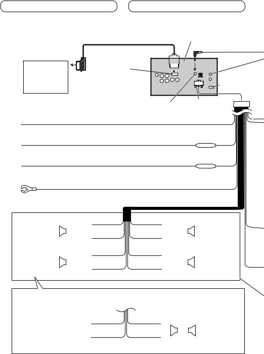
Connecting the power cord
26 pin cable (Supplied with Navigation unit) |
This product |
|
Navigation unit can be connected (AVIC-U220(sold separately)).
Please contact your dealer to inquire about the connectable navigation unit.
Insert the 26 pin cable in the direction indicated in the figure. 
RGB input 

Antenna input 


AUX jack (3.5 ø) (AVH-P4200DVD only)
Use a mini plug cable to connect with auxiliary device. Microphone input (AVH-P3200BT only)
Yellow
Connect to the constant 12 V supply terminal.
Orange/white
Connect to lighting switch terminal.
Red
Connect to terminal controlled by ignition switch (12 V DC).
Fuse resistor
Fuse resistor
(AVHP4200DVD only)
Black (chassis ground)
Connect to a clean, paint-free metal location.
|
|
|
White |
Gray |
|
|||
Front speaker |
|
|
|
|
|
|
|
Front speaker |
|
|
|
|
|
|
|
||
|
|
|
|
|
|
|
||
|
|
|
|
|
|
|
|
|
Left |
|
|
White/black |
Gray/black |
Right |
|||
|
|
|
|
|
|
|
|
|
|
|
|
Green |
Violet |
|
|||
Rear speaker or |
|
|
|
|
|
|
|
Rear speaker or |
|
|
|
|
|
|
|
||
Subwoofer (4 Ω) |
|
|
|
|
|
|
|
Subwoofer (4 Ω) |
|
|
|
Green/black |
Violet/black |
|
|
|
|
|
|
|
|
|
|
|
|
|
When using a subwoofer of 70 W (2 Ω), be sure to connect with Violet and Violet/black leads of this unit. Do not connect anything to Green and Green/black leads.
Green |
Violet |
|
||||
Not used. |
|
|
|
|
|
Subwoofer (4 Ω) |
|
|
|
|
|
||
|
|
|
|
|
× 2 |
|
|
|
|
|
|
|
|
Green/black |
Violet/black |
|
||||
|
|
|
|
|
|
|
6
Connecting the units
4 m (13 ft. 1 in.) |
Microphone (AVH-P3200BT only) |
|
Wired remote input
Hard-wired remote control adaptor can be connected (sold separately).
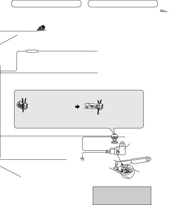
Fuse resistor
Violet/white
Of the two lead wires connected to the back lamp, connect the one in which the voltage changes when the gear shift is in the REVERSE (R) position. This connection enables the unit to
sense whether the car is moving forwards or backwards.
Yellow/black
If you use an equipment with Mute function, wire this lead to the Audio Mute lead on that equipment. If not, keep the Audio Mute lead free of any connections.
Connection method
1. Clamp the lead. 2. Clamp firmly with 


 needle-nosed pliers.
Note:
·The position of the parking brake switch depends on the vehicle model. For details, consult the vehicle Owner’s Manual or dealer.
Light green |
|
|
Used to detect the ON/OFF status of the parking |
|
Parking brake |
brake. This lead must be connected to the power |
Power supply side |
switch |
supply side of the parking brake switch. |
|
|
|
Ground side |
|
Blue/white |
|
|
Connect to system control terminal of the power amp or |
|
|
auto-antenna relay control terminal (max. 300 mA 12 V DC). |
|
|
With a 2 speaker system, do not connect anything to the speaker leads that are not connected to speakers.
Note:
· Change the initial setting of this unit (refer to the Operation Manual). The subwoofer output of this unit is monaural.
English
7

Connecting the units
When connecting to separately sold power amp
Rear output |
(AVH-P4200DVD/AVH-P3200BT only) |
||
Front output |
|
|
|
|
|
Power amp |
|
|
|
(sold separately) |
|
|
|
To rear output |
|
|
|
Power amp |
|
|
|
(sold separately) |
|
|
|
To front output |
|
Subwoofer output |
(AVH- |
Power amp |
|
This product |
P4200DVD |
(sold separately) |
|
only) |
To subwoofer |
||
|
|||
|
|
output |
|
|
|
Connect with RCA cables |
|
|
|
(sold separately) |
|
System remote control
Blue/white
Connect to system control terminal of the power amp or auto-antenna relay control terminal. (max. 300 mA 12 V DC).
Left |
Right |
|
|
|
|
Subwoofer |
Subwoofer |
|
|
|
|
|
|
|
Front speaker |
Front speaker |
|
|
|
|
|
|
|
Rear speaker |
Rear speaker |
Perform these connections when |
|
|
|
|
|
using the optional amplifier. |
|
|
8

Connecting the units
When connecting with a rear view camera
When this product is used with a rear view camera, it is possible to automatically switch from the video to rear view image when the gear shift is moved to REVERSE (R).
 WARNING
USE INPUT ONLY FOR REVERSE OR MIRROR IMAGE REAR VIEW CAMERA. OTHER USE MAY RESULT IN INJURY OR DAMAGE.
 CAUTION
•The screen image may appear reversed.
•The rear view camera function is to be used as an aid for backing into a tight parking spot. Do not use this function for entertainment purposes.
•Objects in the rear view may appear closer or more distant than they actually are.
|
|
CAUTION |
|
Rear view camera input (R.C IN) |
|
You must use a camera |
|
(AVH-P4200DVD/AVH-P3200BT only) |
which outputs mirror |
||
reversed images. |
|||
|
|
||
|
To video output |
||
|
|
Rear view camera |
|
|
|
(sold separately) |
|
|
RCA cable (sold separately) |
||
This product |
(AVH-P4200DVD only) |
|
|
|
|
Fuse resistor |
|
Violet/white
Of the two lead wires connected to the back lamp, connect the one in which the voltage changes when the gear shift is in the REVERSE (R) position. This connection enables the unit to
sense whether the car is moving forwards or backwards.
•It is necessary to set Camera Polarity properly in System when connecting the rear view camera.
English
9
Connecting the units
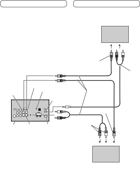
When connecting the external video component and the display
Display with RCA input jacks (sold separately)
To video input
To audio input
Rear monitor output (V OUT)
|
(AVH-P4200DVD/AVH-P3200BT only) |
RCA cables |
Video input (V IN) |
|
(sold separately) |
|
|
|
|
Rear audio output |
Mini pin plug cable |
|
(REAR AUDIO OUT) |
|
|
(sold separately) |
|
|
|
|
|
|
To video output |
|
To audio outputs |
|
This product |
Audio input (AVH-P4200DVD only) |
|
|
(L IN, R IN) |
|
External video component (sold separately)
• It is necessary to change AV Input in System when connecting the external video component.
When using a display connected to rear video output
This product’s rear video output and rear audio output are for connection of a display to enable passengers in the rear seats to watch the DVD, etc.
 WARNING
Never install the display in a location where it is visible to the driver while driving.
10
Installation
 Note
Note
•Check all connections and systems before final installation.
•Do not use unauthorized parts as this may cause malfunctions.
•Consult your dealer if installation requires drilling of holes or other modifications to the vehicle.
•Do not install this unit where:
—it may interfere with operation of the vehicle.
—it may cause injury to a passenger as a result of a sudden stop.
•Do not install the display where it may (i) obstruct the driver’s vision, (ii) impair the performance of any of the vehicle’s operating systems or safety features, including air bags, hazard lamp buttons or (iii) impair the driver’s ability to safely operate the vehicle.
•The semiconductor laser will be damaged if it overheats. Install this unit away from hot places such as near the heater outlet.
•Optimum performance is obtained when the unit is installed at an angle of less than 30°.
•When installing, to ensure proper heat dispersal when using this unit, make sure you leave ample space behind the rear panel and wrap any loose cables so they are not blocking the vents.
Leave ample space |
|
Dashboard |
|||
|
|
|
|
|
|
|
|
|
|
|
|
|
|
|
|
|
|
|
|
|
|
|
|
|
|
|
|
|
|
|
|
|
|
|
|
|
|
|
|
|
|
|
|
|
|
|
|
Installation using the screw |
English |
|
holes on the side of the unit |
||
|
||
Fastening the unit to the factory |
|
|
radio-mounting bracket. |
|
Position the unit so that its screw holes are aligned with the screw holes of the bracket, and tighten the screws at 3 or 4 locations on each side.
If the pawl gets in the way, bend it down.
Factory radio mounting bracket
Use either truss |
|
(5 mm × 8 mm) or |
|
flush surface (5 mm |
|
× 9 mm) screws, |
|
depending on the |
Dashboard or console |
bracket screw holes. |
•To some types of vehicles, this unit cannot be properly installed. In such case, use the optional installation kit (ADT-VA133).
 Note
Note
In some types of vehicles, discrepancy may occur between the unit and the dashboard. If this happens, use the supplied frame to fill the gap.
11
Installation
Installing the microphone (AVH-P3200BT only)
Installation notes
Install the microphone in a position and orientation that will enable it to pick up the voice of the person operating the system.
 CAUTION
•It is extremely dangerous to allow the microphone lead to become wound around the steering column or gearstick. Be sure to install the unit in such a way that it will not obstruct driving.
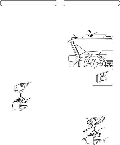
When installing the microphone on the sun visor
1.Install the microphone on the microphone clip.


 Microphone
Microphone clip
2.Install the microphone clip on the sun visor.
•With the sun visor up, install the microphone clip. (Lowering the sun visor reduces the voice recognition rate.)
Microphone clip
Clamp
Use separately sold clamps to secure the lead where necessary inside the vehicle.
When installing the microphone on the steering column
1.Install the microphone on the microphone clip.
Microphone
Microphone base
Fit the
microphone lead
into the groove.
Microphone clip
•Microphone can be installed without using microphone clip. In this case, detach the microphone base from the microphone clip. To detach the microphone base from microphone clip, slide the microphone base.
12
 Loading...