


PRODUCT NO.23102
ASAHI PENTAX SPOTMATIC
TABLE OF CONTENTS
|
|
Page |
INTRODUCTION |
|
2 |
ASSEMBLY AND ADJUSTMENT OVERVIEW |
3 |
|
1. ASSEMBLY AND ADJUSTMENT OF SHUTTER AND FILM TRANSPORT MECHANISM |
|
|
a. |
Shutter Curtains |
4 |
b. |
Parallel Adjustment of Shutter Curtain Edges |
6 |
c. |
Assembly and Adjustment of Selector Gear Parts |
6 |
d. |
Assembly and Adjustment of Film Transport Mechanism |
9 |
e. |
Assembly and Adjustment of Intermediate Gear Parts |
10 |
f. |
Assembly and Adjustment of Selector Gear Mechanism |
13 |
g. |
Assembly and Adjustment of Counter Dial Mechanism |
18 |
h. |
Assembly and Adjustment of Rapid Wind Lever Seat |
19 |
2. MIRROR HOUSING |
|
|
a. |
Points to be borne in mind when making adjustment |
20 |
b. |
Installation of Mirror Housing to Body Proper |
23 |
3. ASSEMBLY AND ADJUSTMENT OF COUPLER GEAR PARTS |
24 |
|
4. ADJUSTMENT OF SHUTTER ACTUATOR PLATE B (05140) |
26 |
|
5. ASSEMBLY AND ADJUSTMENT OF X SYNCHRO CONTACT |
27 |
|
6. ADJUSTMENT OF SHUTTER EXPOSURE TIMING |
|
|
a. |
Adjustment of Bounce Stopper Mechanism |
27 |
b. |
Adjustment of Shutter Curtain Speed |
27 |
c. |
Adjustment of High Speed Exposure Timing (1/60 sec-1/1000 sec) |
28 |
d. |
Adjustment of Slow Speed Exposure Timing (1 sec-1/30 sec) |
29 |
e. |
Bonding of Parts for Adjustment Purposes |
30 |
f. |
Irregularity of Exposure Timing |
30 |
g.Adjustment of Exposure Timing at Various Positions
of Picture Format |
30 |
7. ADJUSTMENT OF SYNCHRO CONTACT MECHANISM |
|
a. Adjustment of Time Lag at X Contact |
31 |
b. Adjustment of Time Lag at PP Contact |
32 |
8. ASSEMBLY AND ADJUSTMENT OF SELF-TIMER |
32 |
ADDENDUM: Exposure meter troubleshooting and repair |
33 |
SERVICE MEMORANDUM 1: Ammmeter installation and adjustment |
35 |
SERVICE MEMORANDUM 2: Reflex mirrot problems |
37 |
23102 |
Page 1 |
INTRODUCTION
This Service Manual is prepared for servicing Product No. 23102-Asahi Pentax Spotmatic Camera-which is an improved model of Product No. 231. While no marked basic changes exist between Product No. 23102 and Product No. 231, changes mostly pertain to the following mechanical structures
Sprocket Parts
Mechanical Parts on Mirror Housing of Wind-Up Shaft Side
A Part of Exposure Meter, and
Other Minor Parts
Consequently, with the exception of the aforementioned parts, this Service Manual will also apply to Product No. 231.
Classification of Parts Numbers of Product No. 23102
Parts Number is composed of five figures. Of the five figures, the first two denote the mechanical structures which are classified as follows
01 Cover Plates and Back Cover
02 Mirror Housing and Prism Seat
03 Film Winding Mechanism
04 Film Rewinding Mechanism
05 Shutter Mechanism
06 Slow Speed Shutter Mechanism
07 Slow Speed Governor
08 Self-Timer Governor
10 Exposure Meter Mechanism
12 Optical Parts
23102 |
Page 2 |
ASSEMBLY AND ADJUSTMENT
Note: Before assembling, disassembled parts need a careful washing and/or dusting with either a piece of cloth or a blower. General rules are summarized below:
Parts equipped with rotating shafts and/or shaft bearings should be thoroughly washed with high quality gasoline or benzine. Especially, the parts lubricated with “L” lubricants need careful washing and drying. However, the pipes containing curtain springs and governor assembly should never be immersed in cleaning liquid for washing purposes.
Exposed plated and anodized parts should be throughly wiped either with a brush or with a clean piece of cloth. When stains are found, lightly wipe off the stained parts with a clean piece of cloth soaked with liquid composed of ether and alcohol at the ratio of 60% and 40%.
Painted parts need only be lightly dusted with a brush. Stains on the outer surface of black-finished cameras should be wiped either with a silicon cloth (similar to the one usually used for wiping glasses and is readily available on the market) or with the aforementioned liquid (60% ether and 40% alcohol). Wipe them very lightly so as not to erase the engraved white letters.
For wiping optical elements, mixed liquid comprising 70% ether and 30% alcohol should be used. For this purpose, a clean piece of cotton or hemp cloth, properly washed beforehand and entirely devoid of starch, or a piece of soft paper is recommended.
For wiping plastic parts (such as Fresnel and ground glass), use mixed liquid composed of 50% ether and 50% alcohol, which gives satisfactory results.
Stained mirror surface should be wiped very lightly with a piece of cloth soaked with mixed liquid composed of alcohol and ether.
Ammeters, CdS cells, variable resistors and semi-fixed resistors should never be washed.
It is of utmost importance to observe the right kind of lubricants, lubricating positions and lubricant quantity. Lubrication should be in strict accordance with the attached list of lube oils, as wrong use of oil will invariably result in malfunctioning of various parts and may cause defects.
23102 |
Page 3 |
1. Assembly and Adjustment of Shutter and Film Transport Mechanism
a. SHUTTER CURTAINS
Insert the 2nd curtain pinion shaft (05062) and pinion shaft collar (05135), one after another, into the top mec. plate (03001), and retain (05135) with the pinion shaft collar retainer screw (05136).
Check if the clearance between the pinion shaft collar (05135) and the top mec. plate (03001) along the shaft direction is adequate. The pinion shaft will not rotate smoothly without an adequate clearance. Adjustment of the clearance should be made with (W6) washers.
Ease the pinion shaft collar retainer screw (05136). Shift the pinion shaft collar (05135) downward. Apply (L-1) lubricant between (05062) and (03001) and then fix (05135) at its original position.
Fix the bottom shaft rest assembly (05003) to the body proper (01001) with the mec. plate retainer screw (03072) and screw (SM 1.7 x 2.5).
Insert the 1st curtain pinion shaft (05061) into the top mec. plate (03001). Insert the curtain shaft collar D (05076) and two 1st curtain wind shafts (05066) into (05061), and fix (05066) to (05061) with two pinion shaft retainer screws (05102).
Insert the 1st curtain roller (05067) and then the 2nd curtain wind shaft (05065), around which the 2nd shutter curtain is glued, to (05062), and fix (05065) to (05062) with one of the pinion shaft retainer screws (05102).
Insert the curtain shaft collar C (05075) into (05061), and (05067) and (05076) into (05062), respectively.
Install the bottom ends of (05061) and (05062) into the respective holes of (05003), assemble (03001) with (01001), and retain (03072) with screw (FM 1.7 x 3).
Check if the clearance of the 1st curtain pinion shaft (05061) along the shaft direction is adequate. Adjustment of the clearance should be made with (W6) washers, putting them between (05003) and (05075).
Insert two 2nd curtain rollers (05068) and one curtain shaft collar A (05073) into the 1st curtain spring shaft (05059) to which the 1st curtain is fixed. Insert the other curtain shaft collar A (05073) into the 2nd curtain spring shaft (05060) to which the 2nd curtain is fixed.
Insert (05059) and (05060) to the respective holes of (01001), and install the curtain shaft seat (05001) in (05059) and (05060) through the bottom of (01001), and retain (05001) with three small screws
(SM 1.7 x 3).
Screw one worm wheel (05040) to (05059) and another to (05060).
Slowly rotate (05040) counter-clockwise 2 or 3 times with a screw-driver to tension the curtain springs. Install the worm (05041) in the hole of (05001) and gear it with (05040). Lightly screw two set screws (Set T 1.4 x 2) in (05001).
Final adjustment of the curtain spring tension should be made when adjusting the curtain travel speed mentioned elsewhere.
23102 |
Page 4 |

23102 |
Page 5 |

b. PARALLEL ADJUSTMENT OF SHUTTER CURTAIN EDGES
With the special tool 231K-E35-A, check if the 1st and 2nd shutter curtain edges (05023) are completely in parallel with each other at the center of the picture format. Also check if the edges (05023) are in parallel with the vertical lines of the frame of the format.
If not in parallel, peel off either one of the 1st or 2nd curtain ribbons (05126) and (05127), and re-glue it correctly so that the edges are in complete parallel with each other.
Note: |
When the shutter curtains are replaced, first install the pinions (0-05061) and (0-05062) in the |
|
camera body, and then glue the curtain ribbons (05126 & 05127), making sure that the curtain |
|
edges (05023) are completely paralleled. |
c. ASSEMBLY AND ADJUSTMENT OF SELECTOR GEAR PARTS
The relative position of the shutter curtains and the bottom selector gear (0-05036) should be determined after assembling (0-05036) with the high speed lever (0-05005), by gearing the 2nd curtain pinion (05038) with the bottom selector gear (0-05036), in the wound condition of the shutter curtains as illustrated in Diagram 3. The relative position of the 2nd curtain edge (05023) to the vertical lines of the frame of the picture format of the body proper (01001) should be checked with the special tool 231K-A01, E23-A.
Apply “L-1” lubricant on (0-05036) and (0-05062).
Note: |
When resetting the shutter curtains to the uncocked position, do it slowly. |
23102 |
Page 6 |
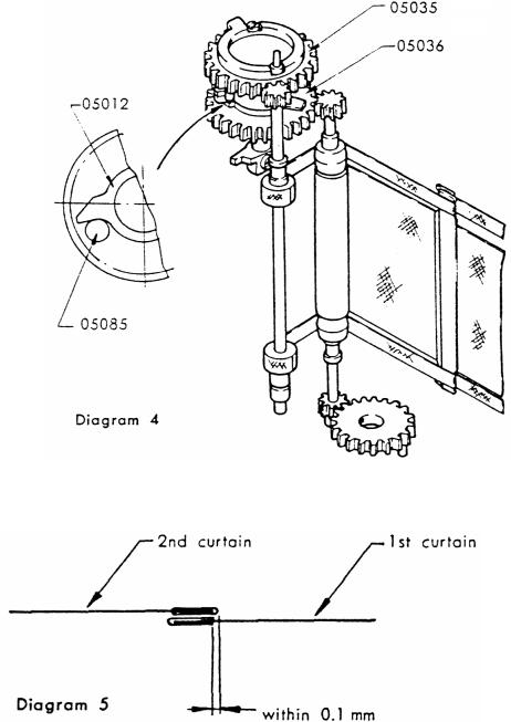
Insert the top selector gear (0-05035) into the selector gear shaft bearing (05043). As illustrated in Diagram 4, engage the top selector gear (0-05035) with the 1st curtain pinion (05038) so that the top selector gear stud (05085) of the top selector gear (05035) makes contact with the bottom selector gear retainer plate A (05012) of the bottom selector gear (0-05036).
Overlapping of the 1st and 2nd shutter curtain edges should be adjusted as illustrated in Diagram 5.
23102 |
Page 7 |
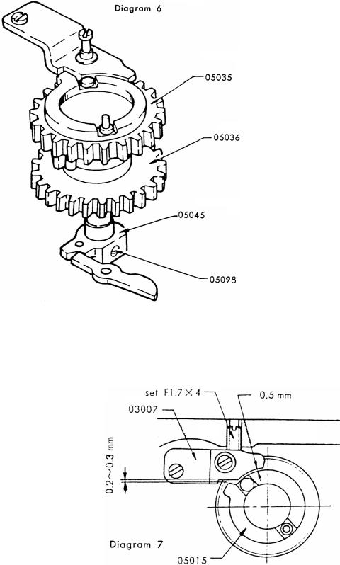
Assemble the top speed selector retainer (0-05045) and the shaft of (0-05035) with particular attention not to change the relative position of the top selector gear (0-05035) to (0-05036), and retain it with the selector gear shaft retainer screw (05098). This can be done easily when the shutter is not cocked. (Diagram 6)
Affix the counter dial actuator lever (0-03018) to the countor dial actuator lever shaft (03059), and the top 2nd gear (0-03024) to the top 2nd gear shaft (03041). Set the shutter curtains in the wound condition, and affix the stopper (03007) at a position where there is a clearance of approx. 0.2-0.3 mm between the stopper and the projected part of the top selector gear retainer plate (05015) and where there is a clearance of approx. 0.2 mm between the stopper and the outer periphery of (05015). After fixing (03007), turn the screw (Set F 1.7 x 4) on the back of the body proper (01001) until it reaches the side of (03007).
Note: Do not force the screw
(Set F 1.7 x 4) against (03007). Bond the screw with red lacquer through the back of the body proper (01001).
23102 |
Page 8 |
d. ASSEMBLY AND ADJUSTMENT OF FILM TRANSPORT MECHANISM
First, put the sprocket collar (03058) and (W 30) onto the sprocket (03057-2) using grease G-1, the former at its top and the latter at its bottom. Install them in the body proper (01001). Then set (LW 13), (W 28), clutch ring (03095), speed dial knob retainer screw (05100) and sprocket spring (03089) onto the sprocket shaft (03054-2). Insert this assembled parts into the aforementioned sprocket (03057-2) through the bottom of the body proper (01001), and fix the bottom mech. plate (03002) onto (01001).
Fasten the sprocket (03057-2) from its side with the sprocket retainer screw (03055-2), assuring that the tip of the screw go right into the long slot of (03095).
While pushing the sprocket shaft (03054-2) from its bottom, rotate (03057-2) with your fingertip to check if it functions smoothly. Then push (03054-2) again from its bottom and rotate (03057-2) several times with your finger, after which lift your finger to check if (03054-2) remains recessed by dint of the functioning of the clutch but satisfactorily reverts itself to its original position once (03057-2) is again rotated.
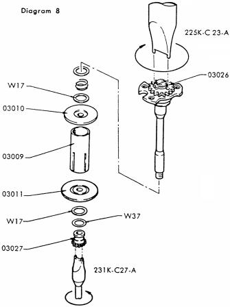
Assemble the spool (03009), top take-up spool brim (03010) and bottom take-up spool brim (03011) in one body, and install it in the spool chamber of the body proper (01001). Drop the wind-up shaft (03042) into the body proper (01001) through its upper hole and affix the wind-up shaft bearing (03043) to the body proper (01001) with small screw (SM 1.7 x 3.5) through the top mec. plate (03001).
With the special tool 231 K-C 27-A, screw the bottom main gear (03027) clockwise onto the wind-up shaft (03042) through the bottom of (01001). When doing so, see to it that the wind-up shaft (03042) is retained intact with the special tool 231 K-C 27-A so that it will not rotate.
While holding (03027) steadily with the special tool 231 K-C 26-A, fasten the top main gear (03026), turning it clockwise with the special tool 231 K-C 23-A.
Note: Do not under any circumstances turn and fasten the bottom main gear (03027).
23102 |
Page 9 |
Slightly rotate the top main gear retainer screw (03044) clockwise with a screwdriver, and ease the force of your driver-holding hand, at which determine if the bottom main gear (03026) will revert itself steadily, say, by 2 or 3 cogs of the gear.
As explained in paragraph……of the Disassembly section, when the wind-up shaft parts are replaced, adjust the torque of the spool with (W 17) washers by carefully comparing it with the torque of the spooi of another Spotrnatic in good working order.
e. ASSEMBLY AND ADJUSTMENT OF INTERMEDIATE GEAR PARTS
Note Lubricate the intermediate gear shaft (05048) very slightly. If oiled excessively, it will invariably result in irregularity of the shutter speed. Do not lubricate the top intermediate gear (05033) or the bottom intermediate gear (05034).
Set the shutter curtain in the wound condition with the special tool 231 K-E 15-A. Turn the top main gear retainer screw (03044) with a screwdriver to position the teeth of the counter actuator dial (03021) as illustrated in Diagram 10.
Paying attention not to move the wind-up shaft (03042), assemble the bottom intermediate gear (05034) with (05048) so that the square hole of (05034) will fit the square groove of the intermediate gear shaft (05048), and the top 3rd gear (C 25) will engage with (05034) and the top main gear (C 26).
Turn the non-return arm (03008) clockwise with the tip of tweezers, and check if (03008) is in contact with the side of the bottom part of the bottom intermediate gear (05034).
23102 |
Page 10 |
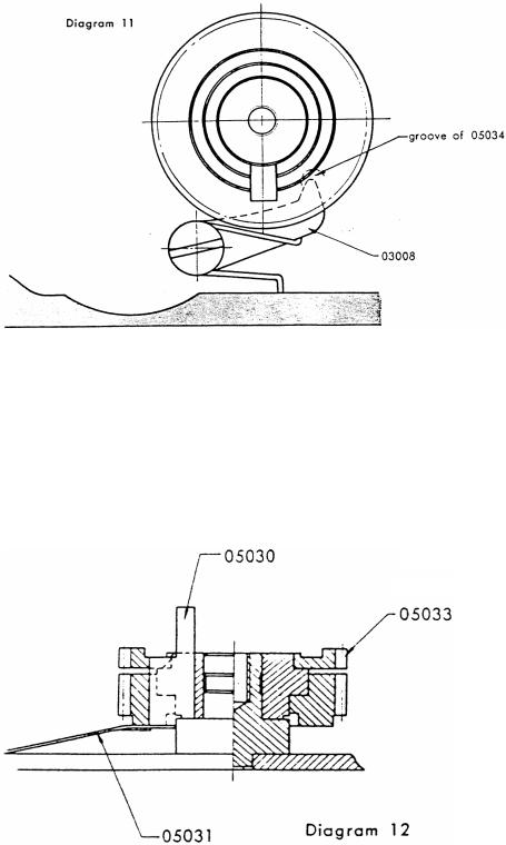
By holding the bottom intermediate gear (05034) to prevent it from floating, turn the top main gear retainer screw (03044) clockwise with a screw-driver until the tip of the non-return arm (03008) drops into the bottom groove of the bottom intermediate gear (05034).
When the force of the screwdriver is eased, the bottom intermediate gear (05034) slightly revolves clockwise with the reversing strength of the wind-up shaft (03042) and stops when it hits the non-return arm (03008).
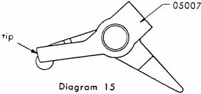
Carefully install the spill (05030) in the square hole of the bottom intermediate gear (05034).
Note: Be careful not to install the spill upside down.
Slowly press the spill with the tip of tweezers to check if the spill goes up and down smoothly with the tension of the spill spring (05031). Then install the top intermediate gear (05033), placing it on (05034).
23102 |
Page 11 |
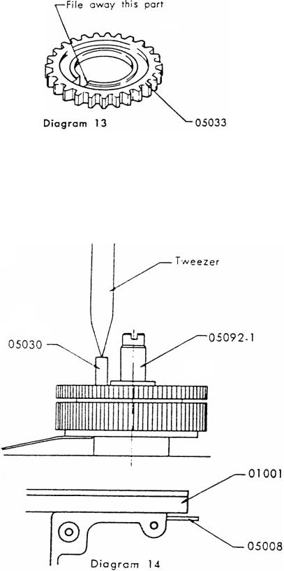
If the groove of (05033), after installation, cannot be properly positioned even though the engaging position of the gear is changed, the groove of (05033) needs adjustment by filing with a fine file.
Place the spill recepctacle plate (05032) on the top intermediate gear (05033), and screw the intermediate gear retainer screw (05092-1) onto the intermediate gear shaft (05048).
Pressing down the spill (05030) with the tip of tweezers, turn the 1st curtain checker arm (05008) counterclockwise as viewed from the top of the body proper, and release the shutter.
Check if the spiil (05030) reverts itself to its original position when the force on the spill (05030) is slowly eased. Cock the shutter again, and repeat this to determine if the spill (05030) moves up and down smoothly.
23102 |
Page 12 |
f.ASSEMBLY AND ADJUSTMENT OF SELECTOR GEAR MECHANISM
(1)Assembly of high Speed Lever Parts
After cocking the shutter, fix the bulb lever (05007) to the bulb lever shaft (05050). If the tip of the bulb lever (05007) hits the selector gear bottom retainer plate (05012), grind the tip of (05007) with a grindstone.
Assemble the high speed lever (0-05005) with the bulb lever (05007), and insert them again into (05050). Hook the high speed lever spring (05120) on the indicator seat (05104) and screw the bulb lever nut (05103) onto (05050). Check with the tip of tweezers if both parts (0-05005 & 05007) move smoothly.
(2)Assembly and Adjustment of Shutter Rod
Assemble the shutter rod spring (05117-1) and the shutter rod (05051) which is calked to the release plate (05004). Insert the shutter rod (05051) into the hole of (03001) through the top of (01001) and also into the lower hole of (01001). At the same time, arrange the intermediate gear retainer screw (05092) to get into the hole of (05004).
Fix an (LW 10) washer to the lower part of (05051) through the bottom part of (01001). From the front of (05051), .fasten the shutter actuator plate (05022) with two shutter actuator plate retainer serews (05088).
Adjustment of (05022) should be made after the mirror housing has been assembled into the body proper (01001). The difference in height between the selector gear retainer plate B (05013) and the bulb lever (05007) must not exceed 1/3 of the thickness of the plate (05013).
When the 1st curtain checker arm (05008) is released after cocking the shutter, (05013) slightly rotates and stops by colliding against the bulb lever (05007). If the bulb lever (05007) is slowly turned counter-clockwise with the tip of tweezers, it should be removed smoothly from (05013).
Note: Remember to prevent the lubricant on the high speed lever (05005) from spreading over the gear parts.
(3)Assembly and Adjustment of Bounce Stopper Mechanism
First, temporarily fasten the bounce stopper adjust screw (05109) to the back of the body proper. Ratain the bounce stopper lever (05010) together with (W 31) with the bounce stopper screw (05101). The tip of the arm (05010) should not have such up-and-down clearance as to get loose from the head of (05109). If necessary, adjust the clearance with (W 27) washers.
23102 |
Page 13 |
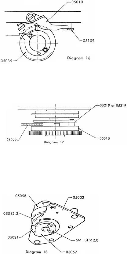
(05010) should not touch the upper part of the top selector gear (05035).
(4)Assembly and Adjustment of the "cocked" Indicator
The "cocked" indicator (05029) must be placed between the high speed cam (05219 or 05319) and the top selector gear retainer plate (05015). Adjustment in this connection should be made by properly bending (05029) with tweezers. Contact of (05029) with either (05019) or (05015) results in irregularity of shutter speeds.
(5)Assembly and Adjustment of Speed Selector Disc
Affix the bulb cam (05021) and the pallet release cam (05057) to the slow speed cam (05020) with two screws (SM 1.4 x 2.0).
Insert (05057) into the lower part of the speed selector disc shaft (05042—2) of the shutter rest (05002), the speed selector disc (05058—2) through its upper part, and fasten them with two screws (REM 1.7 x 3.5).
23102 |
Page 14 |
(6)Assembly of Shutter Rest Plate
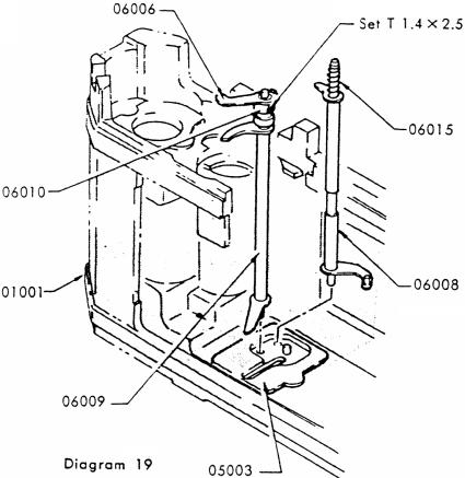
Cock the shutter. Assemble the governor actuator rod spring (06015) and the governor actuator rod (06008), and insert them to the hole of the bottom shaft rest (05003).
Assemble the pallet release rod (06009), the pallet release lever collar (06010) and the pallet release lever top B (06006), and insert them into the hole of the bottom shaft rest (05005) as in the case of (06008). Leave the screw (Set T 1.4 x 2.5) of (06010) loosened.
Apply a small quantity of “L-1 “ lubricant in the hole of the pallet release cam (05057) and on the high speed cam shaft (05047). Fix the long hole of the high speed cam (05019) onto the selector pin (05078). Without moving the high speed cam shaft (05047), match the hole of the pallet release cam (05057) of (05002) with (05047), and then place (05002) on the shutter rest column (03033) and (01001). At the same time, insert the upper end of the governor actuator rod (06008) into the hole of the bottom slow speed lever (06002), and then put the upper end of the pallet release rod (06009) into the hole of (05002).
Fasten (05002) to the body proper (01001) with two screws (SM 1.7 x 3.0), and fix (05002) to the shutter rest column (03033) with the shutter rest retainer screw (05130).
Move the high speed cam (05019) up and down with tweezers. Adjust the tolerance for this up-and- down movement between 0.2 mm and 0.3 mm by placing washers (W 6) onto the high speed cam shaft (05047).
23102 |
Page 15 |
 Loading...