


 Loading...
XNX® Universal Transmitter
Technical Manual
• |
Table of Contents |
• |
Calibration |
• |
Control Drawings |
• |
Safety Information |
• |
Maintenance |
• |
HART® Protocol |
• |
Introduction |
• |
Warnings/Faults |
• |
Warranty |
• |
Installation and Operation |
• |
Specifications |
• |
Index |

XNX Universal Transmitter
Table of Contents
Safety
Warnings 5 Cautions 7 Notes 7 Information 8
1 Introduction
1.1 Product Description 10 1.1.1 The XNX® Universal Transmitter 10 1.1.2 20 mA/HART® Output 11 1.1.3 Communications 11 1.1.4 Certifications 11 1.1.5 Patents 12
1.2 Product Overview 12 1.2.1 Enclosure 12 1.2.2 Cover 13 1.2.3 POD 14 1.3 Options 14 1.3.1 Local HART 14 1.3.2 Relays 14 1.3.3 Modbus 15 1.3.4 Foundation Fieldbus 15 1.3.5 XNX Accessories 15 1.4 The XNX Front Panel 17 1.4.1 Controls and Navigation 18 1.4.2 The General Status Screen 19 1.5 Main Menu 22 1.5.1 XNX Menu Map 23
2 Installation and Operation
2.1 Mounting and Location of Sensors 28 2.1.1 Mounting the XNX® Universal Transmitter 28 2.2 Wiring the XNX Transmitter 30 2.2.1 General Wiring Considerations 30 2.2.2 Distance Considerations for Installation 31 2.2.3 POD Connections 36
2.2.4 4-20mA Output, Common Connections, and Power Settings 37 2.2.5 Foundation Fieldbus Wiring 38 2.2.6 Terminal Block Connections 38 2.2.7 EC Personality Wiring 39
XNX Electrochemical Sensor Installation 40 XNX EC Sensor Remote Mounting Kit 41 2.2.8 mV Personality Wiring 43
2.2.9 IR Personality Wiring 46 Connecting a Searchpoint Optima Plus or Searchline Excel 46 Connecting Generic mA Devices 47
2.3 Options 51 2.3.1 Local HART Interface 51 2.3.2 Relays 53 2.3.3 Modbus 53 2.3.4 Foundation Fieldbus 54
2.4 Powering the XNX for the First Time 55 2.4.1 XNX Units Configured for EC, mV, and IR
(except Searchline Excel) 55 2.4.2 LCD and LED Test 56 2.4.3 XNX IR Units Configured for Searchline Excel 56
Table of Contents |
1 |
XNX Universal Transmitter
Table of Contents
2.5 Configuring the XNX Universal Transmitter 57
 Select Language 57
  Set Date & Time 58
|
Set mV Sensor Type |
59 |
|
Set mA Sensor Type |
60 |
|
Range & Alarms |
67 |
|
Latching / Non-Latching |
69 |
|
Set Units |
70 |
|
mA Levels |
70 |
|
Calibration Interval |
71 |
|
Accept New Sensor Type |
72 |
|
Beam Block Options |
72 |
|
Path Length |
74 |
|
Unit ID |
75 |
|
Relay Options |
76 |
|
Fieldbus Options |
77 |
|
Configure Security |
78 |
2.6 Verifying the XNX Configuration |
79 |
|
2.6.1 |
Test Menu |
79 |
|
X Inhibit |
79 |
|
Force mA Output |
80 |
|
Force Relays |
81 |
|
Alarm/Fault Simulation |
81 |
2.6.2 ? |
Information Menu |
83 |
 Alarm/Fault Status 83
 Date & Time 83


 Transmitter Data 83
? Transmitter Status 84


 Sensor Data 85 ?
 Sensor Status 85
  Gas Data 85
  Range/Alarm Settings 85
 mA Level Settings 86
  Fieldbus Settings 86

 Relay Data 86
  ? Event History 87
3 Calibration
3.1  Gas Calibration Menu 90 3.2 Calibration 90 3.2.1 Zero and Span Calibration for XNX EC Sensors, mV
Sensors, and Searchpoint Optima 91 3.2.2 Calibration Procedure 91 3.2.3 Using the Calibration Cup 93 3.2.4 Zero and Span Calibration of XNX EC Hydrogen
Sulfide (H2S) Sensors 94 3.2.5 705/705HT Calibrating 94 3.2.6 Sensepoint/Sensepoint HT Calibrating 94 3.2.7 Calibrating the Searchpoint Optima Plus 94 3.2.8 Zero and Span Calibration for MPD Sensors 97 3.2.9 MPD Flammable Sensor Operational Life 98 3.2.10 XNX EC Sensor Operational Life 98
3.3 Functional Gas Testing (Bump Testing) 99
3.4  Calibrate mA Output 100
3.5 

 Align Excel (Searchline Excel) 100
3.6 
 Soft Reset 101
Table of Contents |
2 |
XNX Universal Transmitter
Table of Contents
4 Maintenance
4.1 MPD Sensor Cartridge Replacement 104
4.2 XNX® EC Sensor Cartridge Replacement 105 4.2.1 Replacing with the Same Cartridge Type 105 4.2.2 Replacing with a Different Cartridge Type 106
5 Warnings and Faults
5.1 Warning Messages 108
5.2 Fault Messages 113
5.3 Informational Messages 124
6 Specifications
6.1 Product Specifications 128
6.2 Sensor Data 130 6.2.1 Operating and Storage Conditions for Performance Tested EC Cartridges 130 6.2.2 EC Sensor Performance Data, Factory Mutual Verified (see Section 6.3) 131 6.2.3 EC Sensor Performance Data, DEKRA EXAM verified (see Section 6.3) 132 6.2.4 Other EC Sensors 133 6.2.5 XNX EC Sensor Cross-sensitivity 135 6.2.6 XNX MPD Sensor Performance Data 142 6.2.7 EN60079-29-1 Performance Approved Gases for mV Sensor Types 143 6.2.8 Other Sensor Performance Data 143
6.3 XNX Certifications by Part Number Series 144 6.3.1 Certification Labels 148 6.4 Product Identification 151 6.4.1 XNX Universal Transmitter 151
6.4.2 XNX EC Replacement Sensors 152 6.4.3 XNX EC Replacement Cells 153 6.4.4 Multi Purpose Detector (MPD) 154 6.4.5 XNX Catalytic Bead and IR Replacement Sensor Cartridges 154 6.4.6 Accessories/Spares 155
7 Control Drawings
7 1 XNX UL/INMETRO 159 7 2 XNX UL/CSA/FM 162 7 3 Remote Sensor Mount 164
Appendix A - HART® Protocol
A.1 HART® Interface 168 ATEX Conditions for Safe Use of Intrinsically Safe HART Handheld Devices 168 A 1 1 HART Sink, Source, and Isolated Wiring 169 A 1 2 DevComm PC-based HART Interface 172
Overview 172 Functions 173 A 1 3 Handheld Online Menu 176
Appendix B - Modbus® Protocol
B 1 Modbus and the XNX transmitter 183 B 2 Modbus Registers 185
Appendix C - Warranty
Warranty Statement 191 Index 192
Table of Contents |
3 |

XNX Universal Transmitter
Table of Contents
Table of Contents |
4 |
XNX Universal Transmitter
Safety
Read and understand this manual before installing, operating, or maintaining the XNX Transmitter. Pay particular attention to the warnings and cautions below. All of the warnings and cautions shown here are repeated in the appropriate sections of the manual.
Warnings: Identify hazardous or unsafe practices which could result in severe injury or death.
Warnings
•Installation must be in accordance with the recognized standards of the appropriate authority in the country concerned.
•Access to the interior of the sensor, when carrying out any work, must only be conducted by trained personnel.
•Before carrying out any work ensure local regulations and site procedures are followed.Appropriate standards must be followed to maintain the overall certification of the sensor.
•To reduce risk of ignition of hazardous atmospheres, conduit runs must have a seal fitting connected within 18 inches (45 cm) of the enclosure.
•To reduce the risk of ignition of hazardous atmosphere, disconnect the equipment from the supply circuit before opening the sensor enclosure. Keep assembly tightly closed during operation.
•Never open the XNX enclosure under power unless the area is known to be non hazardous.
•The sensor must be earthed/grounded for Intrinsic Safety, electrical safety and to limit the effects of radio frequency interference. Earth/ ground points are provided inside and outside the unit. EMI note for applications using shielded cable: Cable shield terminations must be made at the cable glands with suitable EMI type glands. Avoid terminating cable shields at the Earth ground lug inside the XNX enclosure. In cases where wiring is in pipe, a shielded cable is not required.The external terminal is only a supplemental bonding
connection where local authorities permit or require such a connection.
•Take care when handling EC sensor cells as they may contain corrosive solutions.
•Do not tamper or in any way disassemble the sensor cells.
•Do not expose to temperatures outside the recommended range.
•Do not expose the sensor to organic solvents or flammable liquids.
•At the end of their working lives, sensors must be disposed of in an environmentally safe manner, in accordance with local waste management requirements and environmental legislation. Do NOT incinerate sensors as they may emit toxic fumes.
•High off-scale readings may indicate an explosive concentration of gas.
•Verify all outputs, including display, after installation, after service events, and periodically to ensure the safety and integrity of the system.
•Do not use the XNX Universal Transmitter in oxygen-enriched atmospheres. Concentrations displayed will be adversely affected by oxygen depletion.
•After changing parameters with a handheld device, verify that the parameter settings are correct at the transmitter.
•The factory-set passcodes must be reset to prevent unauthorized access to the transmitter’s menus.
Introduction |
5 |

XNX Universal Transmitter
•When the transmitter is equipped with the optional Remote Mount Kit, the remote sensor must be securely mounted in a fixed position.The Remote Sensor kit is not intended to be used as a hand-held sensor.
•Enclosures of remotely mounted sensors contain aluminum. Be careful to avoid ignition hazards due to impact or friction when installed in Zone 1 locations.
•Install the junction box according to local codes and manufacturer’s requirements.
•The enclosures of remotely mounted 705HT sensors contain aluminum. Be careful to avoid ignition hazards due to impact or friction when installed in Zone 1 locations.
•Power off the transmitter before changing S3 or S4. Both switches must be set in either Source or Sink prior to applying power.
•Minimum and maximum controller alarm levels should not be set at less than 10% or greater than 90% of the full scale range of the sensor. Limits are 60% LEL or 0.6mg/m3 for agency performance certification.
•When configuring or communicating with the transmitter using the front panel displays, resume monitoring by exiting all menus and returning to the General Status menu manually. No time outs are invoked.
•When selecting a new target gas for units with a Searchpoint Optima Plus, the sensor must be recalibrated.
•XNX Universal Transmitters carrying UL/CSA/FM approvals that are configured for devices measuring %LEL will not allow adjustments to the full scale value.The range is fixed at 100%.
•There is a potential loss of sensitivity during exposure to high concentrations of H2S. Under these conditions, set the control unit to latch at overrange. In standalone configuration, set alarms to latching. When resetting the overrange or alarm, verify correct operation of the transmitter.
•Keep the passwords in a secure area to prevent unauthorized access to the transmitter. If the passwords are lost, resetting the XNX transmitter will require a service technician.
•When the XNX transmitter is placed in Inhibit Mode, alarms are silenced.This will prevent an actual gas event from being reported. Inhibit Mode must be limited to testing and maintenance only. Exit Inhibit Mode after testing or maintenance activities.
•Honeywell recommends periodic bump tests (every 30 days or in accordance with customer site procedures) to the sensor to insure proper operation and compliance with the functional safety rating of the installation.
•As some test gases are hazardous, exhaust the flow housing outlet to a safe area. Do not use the XNX Universal Transmitter in oxygen-enriched atmospheres. (In oxygen-enriched atmospheres, the electrical safety is not given.)
•Exposure to desensitizing or contaminating substances or concentrations causing operation of any alarm may affect sensor sensitivity. Following such events, it is recommended to verify sensor performance by performing a functional gas test (bump test).
•When servicing or replacing sensors, reduce the risk of ignition of hazardous atmosphere by declassifying the area or disconnecting the equipment from the supply circuit before opening the sensor enclosure. Keep the assembly tightly closed during operation.
•Take appropriate precautions when using toxic, flammable, and pressurized cylinders.
•Delays resulting from transmission errors between sensor and
transmitter extend response times T90 by more than one-third.The period until fault indication is 10 seconds.
•The HART interface is subject of this EC-type examination certificate only for the purpose of configuration and maintenance.
Introduction |
6 |
XNX Universal Transmitter
•The options “Modbus interface” and “Foundation Fieldbus interface” are not subject of this EC-type examination certificate.
•Long-term exposure (> 20 minutes) to concentrations exceeding the fullscale range of the H2S sensor type 2 can cause it to lose sensitivity. The measured value may decrease even though high levels of toxic gas are still present. If such conditions can occur, set the control unit to latch at overrange. In standalone operation, set alarms to latching.
When resetting the overrange or alarm, verify correct operation of the transmitter.
Hazardous Location Installation Requirements (UL/CSA)
•To reduce risk of ignition of hazardous atmospheres, conduit runs must have a pour gland installed within 18 inches (457mm) of enclosure.
•All ¾ inch NPT conduit, stopping plugs and adapters must be installed with 5¼ threads (minimum) engaged to maintain Explosion Proof rating.
•Stopping Plugs supplied (Honeywell Part Number 1226-0258) are approved for use ONLY with the XNX Universal Transmitter.
•For units fitted with the Optional Relay Module: Relay Contact Ratings are 250 VAC 5A, 24 VDC 5A Resistive Loads Only.
•Terminal block screws should be tightened to 4.5 lb/in (max).
•Reference XNX Control Drawing 1226E0402 or 1226E0454 for additional information regarding IS function (Local HART and EC Personality).
Hazardous Location Installation Requirements (ATEX)
•Read and understand this manual prior to installation and use.
•Use only certified M25 cable glands for installation.
•Shielded armored cable is required for CE compliance.
•Special Conditions for Safe Use
•The following applies to the HART Barrier intrinsically safe circuits: For installations in which both the Ci and Li of the intrinsically safe apparatus exceeds 1% of the Co and Lo parameters of the associated apparatus (excluding the cable), then 50% of Co and Lo parameters are applicable and shall not be exceeded, i.e. the Ci of the device plus the C of the cable must be less than or equal to 50% of the Co of the associated apparatus, and the Li of the device plus the L of the cable must be less than or equal to 50% of the Lo of the associated apparatus.
•For circuits connected to the EC barrier in which the capacitance and inductance exceed 1% of the permitted values, then the maximum permitted capacitance is limited to 600nF for group IIC and 1uF for group IIIC.
•The connection to the HART circuit shall be rated a minimum of IP 6X.
Cautions
Cautions: Identify hazardous or unsafe practices which could result in damage to property or to the product.
Notes
Notes: Additional useful information.
Introduction |
7 |

XNX Universal Transmitter
Information
Honeywell Analytics assumes no responsibility for equipment that is not installed and used following the procedures in the Technical Manual.
The reader of this manual should ensure that the appropriate equipment has been installed. If in doubt, contact Honeywell Analytics.
Every effort has been made to ensure the accuracy of our documents, however, Honeywell Analytics can assume no responsibility for any errors or omissions in its documents or their consequences. Honeywell Analytics greatly appreciates being informed of any errors or omissions that may be found in the contents of any of its documents. For information not covered in this document, or if there is a requirement to send comments/corrections about this document, please contact
Honeywell Analytics using the contact details given on the back cover of this document.
Honeywell Analytics reserves the right to change or revise the information supplied in this document without notice and without obligation to notify any person or organization of such revision or change. If information is required that does not appear in
this document, contact the local distributor/agent or Honeywell Analytics.
XNX® is a registered trademark of Honeywell International.
HART® is a registered trademark of the HART Communication Foundation.
Modbus® is a registered trademark of Schneider Automation Inc. FOUNDATIONTM is a trademark of Fieldbus Foundation.
Introduction |
8 |
XNX Universal Transmitter
1 Introduction
XNX Universal Transmitter Technical Manual |
9 |
XNX Universal Transmitter
1.1 Product Description
1.1.1 The XNX® Universal Transmitter
The XNX Universal Transmitter is a comprehensive gas detection system designed to operate in hazardous locations1 and utilize multiple sensor technologies, catalytic bead, electrochemical
(EC), or infrared (IR) to detect toxic gases, flammable gases, and oxygen depletion gas hazards. Each technology has a dedicated personality board.
Catalytic bead technology is used with the XNX mV personality board. Catalytic bead sensors respond to a wide variety of combustibles so are typically used for flammable gas detection.
Electrochemical technology is used with the XNX electrochemical board. EC sensors measure toxic gases in low concentrations. The XNX EC sensors employ the patented
Reflex™ cell fault diagnosis routine. Reflex™ checks for cell presence, cell dry-out, and cell open or short circuit. Reflex™ is automatically initiated by the transmitter at eight-hour intervals. It is also initiated on power up or sensor exchange. In the event of a cell failing this test, a sensor fault code is displayed.
Reflex™ diagnostics occur in the first minutes of the power up sequence.
communication board. There are three types of boards: relay, Modbus®, or FoundationTM Fieldbus. See Section 1.1. 2
Communications for additional information.
XNX Universal Transmitter
CL2 |
H2 |
NH3 |
O2 |
|
|
|
|
Multi-Purpose |
|
|
|
|
|||||
|
|
|
|
Detector (MPD) |
||||
ClO2 |
H2S |
NO |
PH3 |
|
|
|
|
Catalytic Bead |
|
|
|
|
Infrared Flammable |
||||
CO |
HF |
NO2 |
SO2 |
|
|
|
|
Infrared Methane/CO2 |
|
|
|
|
|
||||
|
|
|
|
Infrared technology is used with the XNX IR board. IR sensors optically absorb gases that fall into the infrared spectrum.
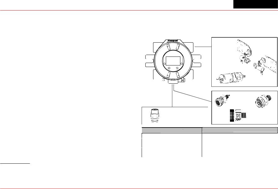
For additional information about any of the three sensor types, refer to the applicable data sheet for the supported sensor in Figure 1.
The XNX Universal Transmitter also allows for an optional
Personality |
Sensor Type |
Suppo ted Senso s |
|
IR |
Point and Open-Path Infrared |
Searchpoint Optima Plus, Searchline Excel |
|
mV |
Flammable and Toxic |
705, 705HT, Sensepoint, Sensepoint HT, MPD |
|
(Catalytic Bead Flammable, IR Flammable and IR CO2) |
|||
|
|
||
XNX EC |
Toxic and O2 Sensing |
Electrochemical sensors, with Hot Swap, pre-calibrated |
|
through Intrinsically Safe (IS) barrier |
|||
. |
|
||
|
|
1There are three main types of gas hazards: flammable, toxic, and asphyxiant. A flammable gas hazard is one in which there is a risk of fire and/or explosion (e.g., a situation in which a gas such as methane, butane, or propane is present). A toxic gas hazard is one in which there is a risk of poisoning (e.g., a gas such as carbon monoxide, hydrogen sulfide, or chlorine is present). An asphyxiant hazard would include a risk of suffocation through oxygen deficiency. (Oxygen can be consumed or displaced by another gas.)
Figure 1. XNX Universal Transmitter and supported sensing technologies
The XNX Universal Transmitter relies on 4-20mA output, refreshed at least every two seconds (once per second is typical), in which the output is proportional to the gas concentration.
Section 1 - Introduction |
10 |
XNX Universal Transmitter
1.1.2 20 mA/HART® Output
All XNX Transmitters provide a 20mA Current Loop with HART
Source (3-Wire) or Isolated (4-Wire) electrical interface based on installation requirements.
The 20mA current loop output provides an analog indication of special states, a proportional output to gas concentration and over range indication per the table below. In the event of a simultaneous alarm and fault, an alarm condition will always override a warning state.
The transmitter uses HART over 4-20mA as the standard communications protocol. Additional optional communication interfaces are available: relay communication, Modbus, or Foundation Fieldbus. Each communication option has a dedicated option board. For additional information, refer to Section 1.3 Options.
1.1.4 
installation in Class I, Division 1, Groups A, B, C and D Hazardous Locations. FM Approvals evaluation includes Class I, Zone
Output |
Description* |
Notes |
|
|
|
|
|
1.0 mA |
Fault |
|
|
|
|
Special |
|
|
Warm-up |
||
2.0 mA |
Inhibit |
State |
|
Bump Test |
Indication |
||
|
|||
|
Calibration |
|
|
|
|
|
|
3.0 mA |
Warning |
|
|
|
|
|
|
4-20 mA |
Gas Concentration |
|
|
|
|
|
|
21 mA |
Over Range |
|
|
|
|
|
*Alarm conditions always take priority over faults and warnings.
HART Protocol provides digital communications with the XNX
Diagnostics. (See Appendix A HART Protocol for additional information)
1.1.3 Communications
The XNX Universal Transmitter is registered with the HART Communication Foundation.
not cover daisy-chained XNX combustible gas transmitters, the use of HART, Modbus, or Foundation Fieldbus protocols for combustible gas performance. HART, Modbus, or Foundation Fieldbus protocols can be used only for data collection or record keeping with regards to combustible gas. The EC cartridge2 and
standards.
European Community ATEX Directive and the prescribed protection methods for installation in Potentially Explosive Atmospheres.
XNX-BT**.***** and XNX-UT**.***** versions are UL classified and INMETRO approved (TÜV Rhineland) for compliance with
both U.S. and Brazilian standards.
See Section 6.2 for additional information on applicable approvals by part number and Section 6.2.1 for marking.
2“Cartridge” and “sensor” are used interchangeably in this document.
Section 1 - Introduction |
11 |
XNX Universal Transmitter
1.1.5 Patents
This table shows details about XNX-related patents.
Patents Applicable to the XNX Universal Transmitter
Patent |
Description |
Application |
|
Number |
|||
|
|
||
|
|
|
|
6,123,818 |
Reflex patent |
Implemented in XNX |
|
6,251,232 |
Reflex patent |
Implemented in XNX |
|
6,351,982 |
Flammable sensor housing |
XNX accepts this sensor |
|
6,395,230 |
Pellistor |
Sensor used in XNX |
|
7,225,661 |
Gas calibration adapter |
Applicable to XNX |
|
7,716,962 |
Method of gas calibration |
Used to calibrate XNX ECC cartridges |
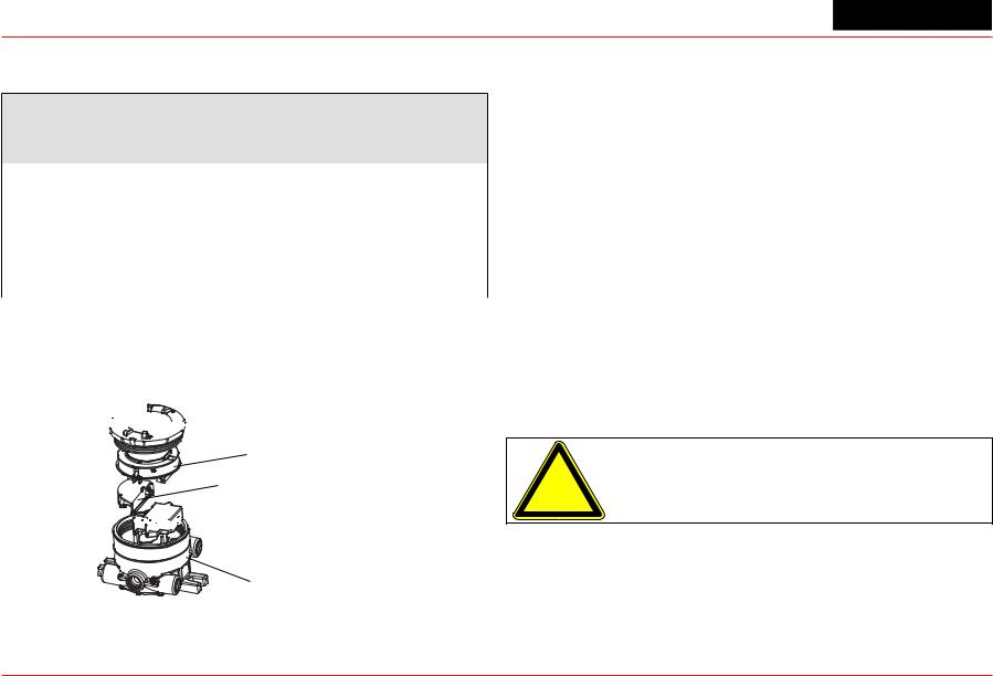
1.2 Product Overview
The XNX transmitter is comprised of the main parts shown below.


 Cover
Cover
Pod
Intrinsically Safe (IS) Barrier for
Optional Local HART Interface


 Intrinsically Safe (IS) Barrier for
Electrochemical Sensor Interface (when equipped)
Enclosure
Figure 2. XNX Exploded View
1.2.1 Enclosure
Available in either Stainless Steel or Aluminum, with 3/4” NPT (UL/CSA or UL/ INMETRO) or M25 (ATEX/IECEx only) threaded cable/conduit ports, the XNX Universal Transmitter enclosure is explosion-proof and suitable for use in -40°F to +149°F (-40°C to
+65°C) operating conditions. A 5-coat marine finishing process provides the highest degree of corrosion protection. For more information on performance specifications, see Section 6 - Specifications.
The XNX enclosure is equipped with five threaded cable/conduit ports providing functional and flexible configurations based on sensor and option choices. See Figure 5 for cable/conduit port assignments and restrictions.
Stopping plugs (HA PN# 1226-0257 or 1226-0258) have been provided to seal unused cable/conduit ports and have been Agency evaluated/approved for use with the XNX enclosure only. The number of stopping plugs varies among available configurations.
Caution: The stopping plugs are for use only with the XNX Transmitter and should not be used with any other device.
Mounting lugs integral to the XNX enclosure allow easy installation on a flat surface or 2”-6” (50-150mm) diameter pipe with the optional Pipe Mount Kit or Ceiling Mount Bracket Kit.
A complete description of XNX accessories can be found in publication 1998-0807 XNX Universal Transmitter Parts List.
Section 1 - Introduction |
12 |
XNX Universal Transmitter
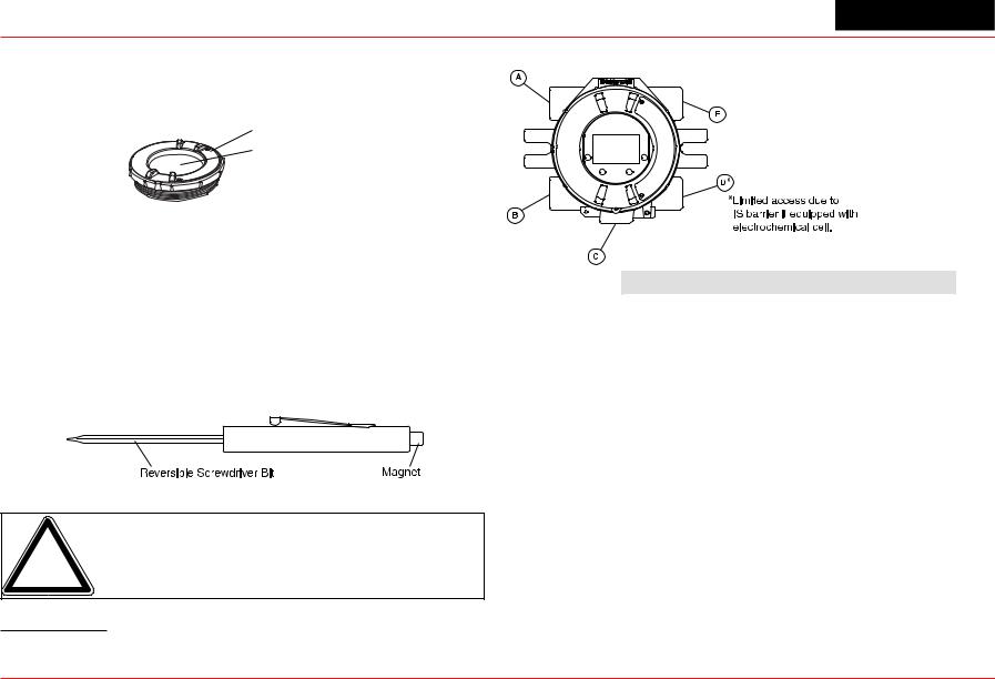
1.2.2 Cover
The transmitter cover is supplied in the identical material specified for the enclosure.
Cover
Tempered Glass Window
 Cover Lock Screw, requires a 2mm hex key (included)
Figure 3. XNX components
A tempered glass window requires the use of the supplied magnetic wand/screwdriver to activate the four user interface switches that are located on the front of the display module. This allows for nonintrusive setup and operation.
A locking screw integrated into the cover provides positive locking that can be removed by using the supplied 2mm hex key3.
Figure 4. Magnetic Wand/Screwdriver
Note: When attaching the cover or stopping plugs, coat the threads to prevent corrosion.
3See the XNX Universal Transmitter Parts List (document 1998-0807) for a description of all of the parts that are shipped with the transmitter.
While relay wiring can use any available cable/conduit port in the XNX enclosure, do not use the same cable/conduit port for both relay reset and relay signal lines to avoid electrical noise.
Option |
Position |
|
|
Local HART Option |
B |
|
|
XNX Electrochemical Sensor - Local/Remote |
C |
|
|
MPD, 705 Series, Sensepoint Series |
C |
|
|
Searchpoint Optima Plus |
A or E |
|
|
Searchline Excel |
Typically C |
|
|
Remote Sensor Connection (except EC ) |
Any remaining |
|
|
Searchpoint Optima Plus - Remote |
Any remaining |
|
|
Modbus |
Any remaining |
|
|
Relays |
Any remaining |
|
|
Power |
Any remaining |
|
|
Figure 5. XNX Universal Transmitter Cable/Conduit Port Assignments
Section 1 - Introduction |
13 |

XNX Universal Transmitter
1.2.3 POD
The POD (Personality, Options, and Display) encloses circuit boards for the personality module, optional interfaces, and display.
The personality module, or circuit board, determines the transmitter behavior based on the sensor type attached to the transmitter (electrochemical cell, catalytic bead sensor, or
infrared) and provides the necessary interface. Connection to the attached sensor is made through the sensor connector accessed via a slot in the POD housing.
The optional communication boards vary depending on the option selected when ordered. Only one of the three available interface options (relays, Modbus, or Foundation Fieldbus) can be attached to the XNX transmitter.
1.3 Options
1.3.1 Local HART
Available with any sensor technology or personality, an external access to the HART interface in the XNX transmitter is provided. An intrinsically safe (IS) barrier inside the transmitter gives the user full control using a hand-held interrogator for programming and configuration. The external interface is installed in the lower left cable/conduit port of the transmitter and is intrinsically safe.
For more information, see Appendix A - HART Protocol.
Figure 7. XNX Universal Transmitter with HART Interface IS Barrier
Figure 6. POD, exploded View
1.3.2 Relays
The relay option (XNX-Relay) provides 3 form “C” (SPDT) normally open/normally closed (NO/NC) contacts for alarm and fault indication. A remote reset input is provided (TB4). Momentarily closing the the circuit between the pins of TB4 performs the same function as the Reset Alarms & Faults command.
The XNX transmitter has three relays: relay 1 is for alarm level 1, relay 2 is for alarm level 2, and relay 3 is for faults and special
Section 1 - Introduction |
14 |
XNX Universal Transmitter
states. Two alarm levels can be set, allowing, for example, a level 1 alarm for the immediate area when a certain gas concentration is detected and a plant-wide level 2 alarm when a greater gas concentration is detected.
The maximum refresh rate of the relays is 2 seconds. See Set Alarm Values for more information.
1.3.5 XNX Accessories
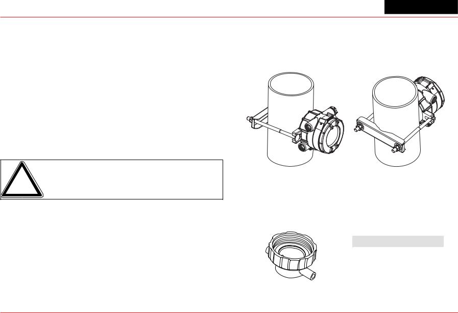
Pipe Mount Kit
The Pipe Mount kit (1226A0358) allows the XNX to be mounted to pipe from 2”-6” (50-150mm) in diameter. The kit includes the pipe mount bracket, two carriage bolts, nuts, and lock washers.
1.3.3 Modbus
The optional Modbus interface allows the XNX to connect to a bus of devices and transmit data to PLCs or controllers.
(For more information, see the Modbus Protocol Manual). Connections to the XNX are made through a pluggable terminal block on the Modbus interface circuit board. Modbus RTU protocol uses ASCII/Hex protocols for communication.
Note: POD options are either relay, Modbus, or Foundation Fieldbus.
1.3.4 Foundation Fieldbus
Foundation Fieldbus is a digital communication system which supports several types of messages. Unlike many traditional systems which require a set of wires for each device, multiple Foundation Fieldbus devices can be connected with a
single set of wires. Foundation Fieldbus overcomes some of the disadvantages of proprietary networks by providing a standardized network for connecting systems and devices.
Figure 8. Pipe-mounted XNX Transmitters
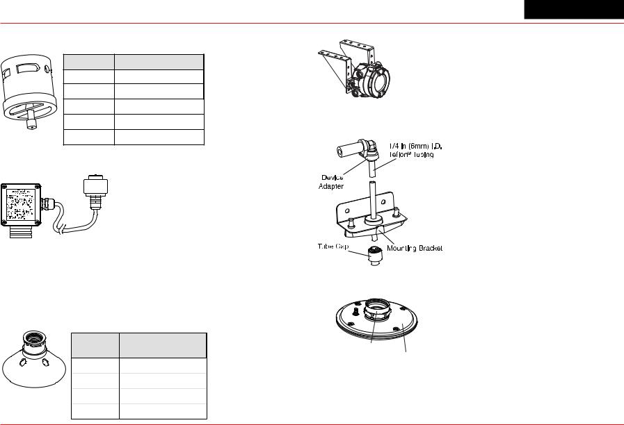
Calibration Gas Flow Adapter
The calibration gas flow adapter is used to apply calibration test gas to the sensor. It attaches to the bottom of the sensor and can be fitted without removing the weatherproof cover. See
Section 3 - Calibration for further details on gas calibration.
Sensor |
Flow Adapter P/N |
|
|
XNX EC |
S3KCAL |
|
|
MPD |
1226A0411 |
|
|
Sensepoint |
02000-A-1645 |
|
|
705 |
00780-A-0035 |
|
|
Section 1 - Introduction |
15 |
XNX Universal Transmitter
Weatherproof Cap |
Ceiling Mount Bracket Kit |
The weatherproof cap protects XNX sensors from harsh weather.
Sensor |
Weatherproof Cap P/N |
|
XNX EC |
Included |
|
MPD |
02000A1640 |
|
Sensepoint |
02000-A-1640 |
|
705 |
00780-A-2076 |
Remote Gassing Kit |
MPD-*TCB1 |
|
|
SPXCDWP (included) |
|
|
Remote Sensor Mounting Kit for XNX EC Sensors |
|
|
|
The remote sensor mounting kit |
|
|
(S3KRMK) allows XNX EC sensors to |
|
|
be remotely mounted via an IS cable |
|
|
kit, up to 50 feet (15 meters) from the |
|
|
transmitter. The kit includes 50 feet of |
|
|
shielded cable, cable glands, and |
|
|
remote terminal box. The cable can be |
|
cut to the required length then terminated at the remote terminal box.
Collecting Cone
The collecting cone improves detection of lighter-than-air gases |
The duct mounting kit (S3KDMK) can |
||
be used with the EC sensor to allow |
|||
such as hydrogen and methane. |
|||
|
|
detection of O2, CO, H2 and H2S gases |
|
Sensor |
Collecting Cone P/N |
in ducts. When combined with the |
|
1226A0382 MPD Adapter Ring |
|||
|
|
S3KDMK EC/MPD Duct Adapter Kit MPD Interface Adapter (1226A0382), |
|
XNX EC |
S3KCC |
the duct mounting kit can |
|
MPD |
02000-A-1642 |
accommodate the MPD to detect flammable gases in a duct |
|
application. The duct mount kit includes the adapter, gasket and |
|||
Sensepoint |
02000-A-1642 |
||
required fasteners. The MPD Interface Adapter includes only the |
|||
|
|
||
705 |
02000-A-1642 |
adapter and requires the S3KDMK duct mount kit. |
|
Section 1 - Introduction |
|
16 |
|
XNX Universal Transmitter
Weather Protector 1.4 The XNX Front Panel
The Extreme Weather Protector (SPXCDWP) is designed to protect the sensor from environmental conditions in outdoor exposure applications.
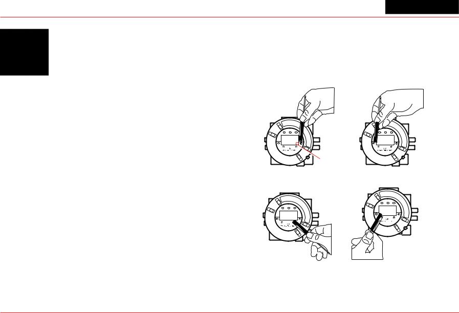
The XNX Transmitter uses magnetic switches to enable nonintrusive operation. To activate a magnetic switch, hold the magnetic end of the screwdriver up to the glass window and slowly swipe the magnet directly over the shaded area.
For best results, hold the screwdriver as illustrated in Figure 9.
|
Switch Actuation |
Enter/Accept |
Visual Indicator |
Escape/Back |
Move Right/Increment Value |
Move Left/Decrement Value |
Figure 9. Using the magnetic wand
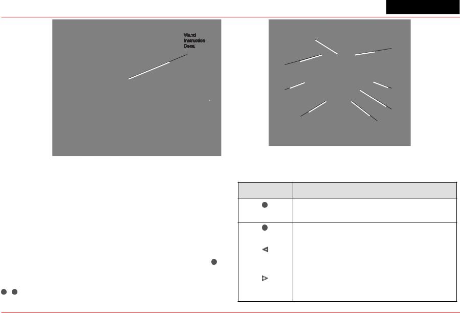
A decal illustrating the proper method for actuating the magnetic switches is placed on the POD of each transmitter.
Section 1 - Introduction |
17 |
XNX Universal Transmitter
Wand
Instruction
Decal

Figure 10. Operation decal
The switch is actuated by the flux lines between the poles of the magnet. This actuation method provides the most consistent response.
A visual indication of the switch actuation will appear in the lower right corner of the XNX display each time the switch is activated.
In some menus where displayed values can be changed, the magnet must be swiped over the switch to cause the numeral on the display to advance through the available values. Use the switch to return to a previous menu or field.
For the purposes of this manual, the instruction to use
, ,  or
or  , means to activate the relevant magnetic switch as described above.
Power LED (green)
|
|
|
|
Fault LED (yellow) |
|
|
|
|
|||
|
|
|
|
|
|
|
|
|
|
|
|
|
|
|
|
|
|
|
|
|
|
|
|
Alarm LED (red) |
|
|
|
||
|
|
|
|
||
|
|
|
|
|
|
Escape |
|
Enter/Accept |
|||
|
|
|
|
|
|
|
|
|
|
|
|
|
|
|
|
Switch Actuation |
|
|
|
|
|
||
|
Move Left |
|
Visual Indicator |
||
|
|
||||
Decement Value |
Move Right |
||||
|
|
|
Increment Value |
||
Figure 11. Front panel display of the XNX transmitter
1.4.1 Controls and Navigation
Command |
Description |
The Enter/Accept switch is used to access menus, accept changes and to answer “yes” to system
Enter/Accept prompts.
The Escape/Back switch is used to return to previous
Escape/Back |
menus or to answer “no” to system prompts. |
|
|
||
|
|
|
|
The Left/Decrement arrow is used to move through |
|
Move Left/ |
menu options or decrement values when entering text |
|
or numbers. |
||
Decrement Value |
||
|
|
|
|
The Right/Increment arrow is used to move through |
|
Move Right/ |
menu options or increment values when entering text or |
|
numbers. |
||
Increment Value |
||
|
Section 1 - Introduction |
18 |
XNX Universal Transmitter
1.4.2 The General Status Screen
 \
\
Figure 12. General Status screen4
The General Status Screen shows the status of the XNX Transmitter.
|
Current Concentration Level |
|
(Numeric) |
Status Indicator |
Concentration Units |
|
|
Current Concentration Level |
Full Scale |
|
|
(Bar Graph) |
Alarm 2 Set Point |
|
|
|
Alarm 1 Set Point |
Figure 13. General Status screen, normal operating mode |
|
The Normal Operating Mode icon  indicates proper operation. The XNX display also shows the concentration level of the target gas in two ways. In the first, a numeric value is shown in the upper right corner of the display in the units selected (ppm,
%LEL, %VOL). The second concentration display is shown in the form of a bar graph representing the current concentration against full scale and in relation to the defined alarm levels. For more information on setting range and alarm levels, see Section 2.6.2 Range/Alarm Settings. See Section 6.2.2, Section 6.2.3, and Section 6.2.4 for negative drift and zero deviation values.
4The LCD screen’s refresh rates are 500 milliseconds (when the LCD heater is off) and 1 second (when the heater is on).
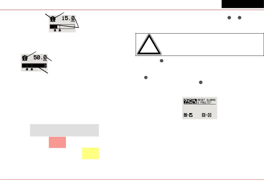
When a warning is triggered, the warning icon  appears and information is displayed on the General Status Screen. The information displayed alternates between screens displaying the gas concentration and the warning code. See Section 5 - Warnings/Faults for more warning code information.
Warning Icon |
Warning Code |
Figure 14. General Status Warning detail
If the Fault icon  is displayed, a fault condition has been triggered and the display will alternate between the target gas concentration and the fault code. See Section 5 - Warnings/ Faults for more fault code information.
Fault Icon |
Fault Code |
Figure 15. General Status Fault detail
In the event of multiple warnings or faults, the user can view all messages with the transmitter’s Event History function.
When an Alarm icon  is displayed, the target gas concentration exceeds one or both preset alarm levels. The General Status Screen displays the gas concentration and the alarm level exceeded.
Section 1 - Introduction |
19 |
XNX Universal Transmitter
Alarm Icon |
Alarm Level Triggered |
|
Target Gas Concentration
Figure 16. General Status Alarm detail
In an over range condition, the alarm icon will display and the target gas concentration bar graph and alarm setpoints will flash.
Alarm Level Triggered
Full Scale
 Concentration
 Concentration Bar, Alarm Setpoints Flash
Figure 17. General Status Over Range detail
Negative values are not displayed and do not appear on the
4-20 mA output, but they are indicated by faults or warnings when preset thresholds are exceeded. (See zero deviation in Section 6.1.1)
In addition to the graphic alarm, fault, and warning indicators, the LEDs on the front panel flash in these patterns based on the condition:
1.4.3 Entering the Menu Structure
Swiping the magnet over the magnetic switch or allows the user to reset faults or alarms, display current settings, or make adjustments to the device.
Note: If the Easy Reset option is set to Lock, alarms and faults cannot be reset without logging in or entering a passcode. For more information, see Section 2.5.1 Configure Security.
Swiping the or “escape” magnetic switch activates the Alarm
Re-set screen and allows alarms to be silenced and faults to be reset.
The switch resets all alarms and faults and returns to the General Status Screen. Use the switch to return to the General Status Screen without resetting the alarms and faults.
Condition |
|
LED1 |
|
|
Red |
Green |
Yellow |
||
|
||||
|
|
|
|
|
Alarm 1 |
Solid |
|
|
|
Alarm 2 |
Flashing |
|
|
|
Warning |
|
|
Solid |
|
Fault |
|
|
Flashing2 |
|
Health |
|
Flashing |
|
1The refresh rate of the LEDs is 0.5 second.
2Special states (Warmup, Inhibit) are not indicated by the Fault LED.
Figure 18. Alarm Reset screen
Two authorization levels control access based upon the security level of the user: Level 1 (routine maintenance) and Level 2
(technician and password administrator). The default passcodes for both levels are “0000” and must be reset after installation
to control access (see Section 2.5.1 Configure Security). In general, access to neither security level restricts the user to viewing the transmitter’s display. If desired, the Easy Reset from Main Status option allows alarm and fault resets without requiring access to either security level.
Section 1 - Introduction |
20 |
XNX Universal Transmitter
Figure 19. Passcode screen
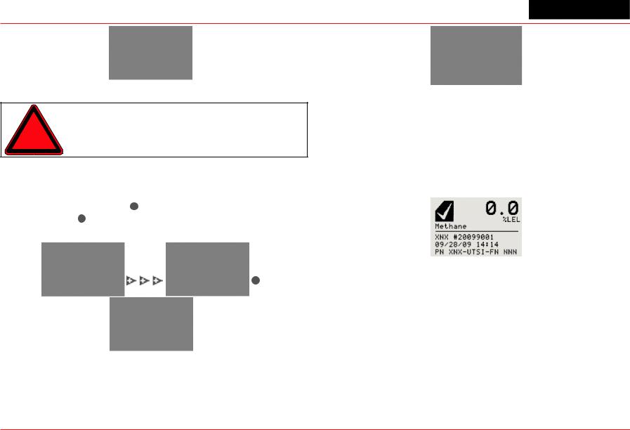
Warning: The factory-set passcodes must be reset to prevent unauthorized access to the transmitter’s menus.
When the Passcode Screen is displayed, the first passcode digit is highlighted. Use the 
 switches to increment or decrement through the values. Once the correct value is displayed for the first digit, accepts the value and moves to the next digit or moves to the previous digit of the passcode.
Figure 20. Entering the passcode
Repeat for each of the remaining digits in the passcode. If the passcode is not entered correctly, the Invalid Passcode screen is displayed and the user is returned to the General Status screen.
Figure 21. Invalid Passcode screen
1.4.4 Displaying Transmitter Information
While in the General Status display, swipe the magnet over the magnetic switch  to display information about the transmitter. The General Status display will replace the bar graph in the lower portion of the screen with the unit’s serial number, the date and time, and the unit’s part number.
Figure 22. General Status Screen with Unit Information
Section 1 - Introduction |
21 |

XNX Universal Transmitter
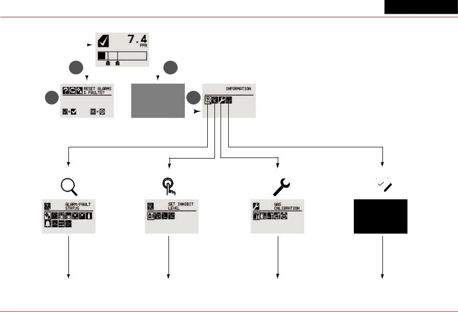
1.5 Main Menu
Once the proper passcode has been entered, the transmitter displays the Main Menu.
Figure 23. The Main Menu
From the Main Menu, a Level 1 user can:
•display the current settings/configuration
•test the transmitter
•calibrate and bump test the transmitter
•configure the unit for language, date and time
The Main Menu consists of these options:
|
|
|
|
|
Menu |
Description |
See |
|
|
|
|
|
|
Section... |
|
||
|
|
|
|
|
|
|
|
|
|
|
|
|
|
|
|
|
|
|
|
|
|
|
Configure |
Provides access to settings to configure the |
2.5.1 |
|
|
|
|
|
|
|
|||
|
|
|
|
|
transmitter and connected devices |
|
||
|
|
|
|
|
|
|||
|
|
|
|
|
|
|
|
|
|
|
|
|
|
Test |
Provides access to tools and settings to allow |
2.6.1 |
|
|
|
|
|
|
simulation of gas events to test the system |
|
||
|
|
|
|
|
|
|
|
|
? |
|
Information |
Displays current settings for the XNX transmitter |
2.6.2 |
|
|||
|
including optional relays and Modbus |
|
||||||
|
|
|
|
|
|
|
|
|
|
|
|
|
|
Gas |
Displays the XNX interface to calibrate sensors |
3.1 |
|
|
|
|
|
|
Calibration |
attached directly to the transmitter |
|
|
|
|
|
|
|
|
|
||
|
|
|
|
|
|
|
|
|
|
|
|
|
|
|
|
|
|
Section 1 - Introduction |
22 |
|||||||
XNX Universal Transmitter
1.5.1 XNX Menu Map
|
|
|
|
|
|
Status Display |
||
|
|
|
|
|
|
|
3 |
|
6 |
|
|
|
|
|
|
||
|
|
|
|
|
|
|||
|
|
|
|
|
|
|
|
|
3 |
|
|
|
|
3 |
|||
|
|
|
|
|
|
|
|
|
|
Alarm/Fault Reset |
Passcode Display |
||||||
|
Display |
|
|
|
|
|||
1. Information Mode |
2. Test Mode |
?
Continued |
Continued |
on page 24 |
on page 25 |
Main Menu
3. |
Calibration |
Mode |
4. Configuration Mode |
|||
|
|
|
|
|
|
|
|
|
|
|
|
|
|
|
|
|
|
|
|
|
|
|
|
|
|
|
|
|
|
|
|
|
|
|
Continued |
Continued |
on page 25 |
on page 26 |
Section 1 - Introduction |
23 |

XNX Universal Transmitter
 Information Mode
 Alarm/Fault Status Alarm/Fault
Confirm Alarm/Fault Reset Reset Alarm/Fault
 Date & Time
 Transmitter ID, Serial #, Revision
Transmitter Data  Transmitter Status
Transmitter Status
 Sensor Type, Serial #, Revision
Sensor Data  Sensor Status
Sensor Status
 Gas Name, ID, Range
Gas Data
 Range Settings, Alarm Settings
Range/Alarm Settings  mA Level Settings
mA Level Settings
 Relay Settings5 Relay Settings
5 Optional relay only
 Fieldbus Settings6
Fieldbus Settings
 Event History
Increment Next/Previous Event
Increment Next/Previous Hour
Increment Next/Previous Day
Increment Next/Previous Alarm
Increment Next Previous Fault
6 Optional Foundation Fieldbus and Modbus only
Section 1 - Introduction |
24 |
XNX Universal Transmitter
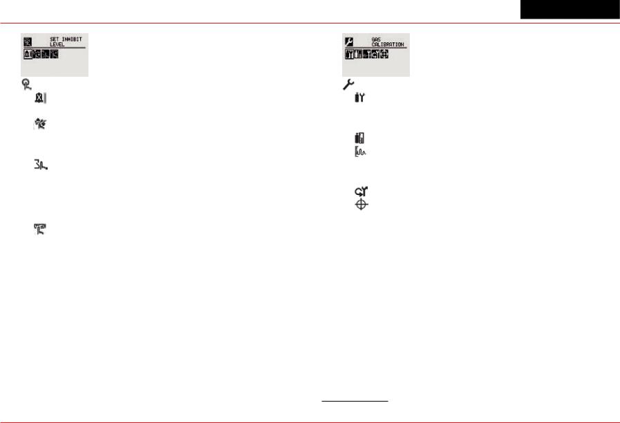
Test Mode |
Calibration Mode |
Inhibit |
Gas Calibration |
Enable/Disable Inhibit |
Enter Span Gas Concentration (Oxygen) |
Force mA Output |
Enter Span Gas Concentration (Not Oxygen) |
Select Current: 0 to 22 mA |
Bump Test |
Accept |
mA Output Calibration |
Force Relay7 |
Adjust 4 mA Output |
Select Relay 1 |
Adjust 20 mA Output |
Select Relay 2 |
Soft Reset8 |
Select Relay 3 |
Align Excel9 |
Accept |
|
Alarm/Fault Simulation |
|
Alarm 1 Simulation |
|
Alarm 2 Simulation |
|
Warning Simulation |
|
Fault Simulation |
|
|
|
8 |
Searchpoint Optima and Searchline Excel only |
7 Optional relay only |
9 |
Searchline Excel only |
|
Section 1 - Introduction |
25 |
XNX Universal Transmitter
Configuration Mode
Select Language
Set Date & Time
Set Date Format
Set Year, Month, Day
Set Hours, Minutes, Seconds
Sensor Type Selection
Set mV Sensor Type10
Set mA Sensor Type11
Gas Selection
Changing the Gas or Units Name
Gas Selections and Alarm Limits Based on mV
Sensor Type
 Range & Alarms
Set Range
Alarm 1 Type Alarm 1 Setpoint
Alarm 1 Latching or Non-latching Alarm 2 Type
Alarm 2 Setpoint
Alarm 2 Latching or Non-latching
Selecting the Numeric Format
 Latching/Non-latching
 Change Meas. Units12
mA Output Levels Change mA for Inhibit
10 Catalytic bead sensor only
11 Searchpoint Optima and Searchline Excel only
12 ECC and mV only
Change mA for Warning Change mA for Overrange Change mA for Low Signal Change mA for Blocked Beam
 Set Calibration Interval
Accept New Sensor Type13
Information screen identifying previous sensor and new sensor
Screen displays new type and old type
 Set Beam Block14
Select Beam Block Threshold Select Time to Beam Block
Select Time to Fault
Set Path Length15
Set New Path Length Configure Unit ID
Edit ID
Clear ID
Default ID
Relay Options16
Select A1
Select A2
 Fieldbus Options17
Change Fieldbus Address
Change Fieldbus Speed Security
Reset and LVL1 LVL1 Code LVL2 Code
13 Electrochemical and catalytic bead sensors only
14 Searchline Excel only
15 Searchline Excel only
16 Optional relay only
17 Optional Foundation Fieldbus and Modbus only
Section 1 - Introduction |
26 |

XNX Universal Transmitter
2 Installation and
Operation
XNX Universal Transmitter Technical Manual |
27 |
XNX Universal Transmitter
2.1 Mounting and Location of Sensors
Caution: Locate transmitters and sensors in accordance with relevant local and national legiislation, standards, and codes of practice.
The placement of sensors should be determined following the advice of experts having specialist knowledge of gas dispersion, experts having knowledge of the process plant system and equipment involved, and safety and engineering personnel. The agreement reached on the location of sensors should be recorded. Consider these factors when locating gas sensors:
•possible damage caused by natural events such as rain or flooding
•ease of access for functional testing and servicing
•how escaping gas may behave due to natural or forced air currents.
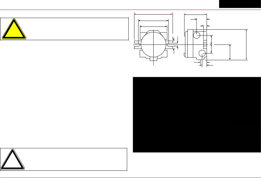
2.1.1 Mounting the XNX® Universal Transmitter
The transmitter can be mounted in a number of ways using the integral mounting tabs. The transmitter can be attached to flat wall surfaces or to Unistrut®. With the optional Pipe Mount kit, the unit can be mounted to pipe of diameter 2” to 6” (50 to 150mm). A ceiling mount bracket kit (1226A0358) is also available.
7.75" 196.85 mm
6.00" 15.4 mm
5.6" 124.24 mm
4.48" |
|
|
113.8 mm |
2.054" |
|
|
|
|
|
52.18mm |
|
|
0.625" |
|
|
15.88mm |
|
0.55" |
|
|
14.35 mm |
|
|
|
1.768" |
|
|
44.90 mm |
|
|
1.768" |
|
|
44.90 mm |
3.176" |
1.67" |
|
80.67 mm |
|
|
|
42.41 mm |
|
|
1.2" |
|
|
31.75mm |
0.945" |
|
|
24mm |
|
6.138"
158.75mm
Note: Agency certifications require that EC and mV sensors face down. Optima sensors must be mounted horizontally.
Figure 24. XNX Universal Transmitter mounting dimensions and clearances
Section 2 - Installation and Operation |
28 |
Loading...