


Pentax TH6110D, TH6220D, TH6110, TH6220, TH6320 Installation Guide
...
Programmable |
FocusPRO® |
|
|
|
|
|
|
||
|
|
|
||
Digital |
6000Series |
|
|
|
Thermostat |
|
|
|
|
Installation |
|
|
|
|
Instructions |
|
|
|
|
|
|
|
|
|
Wallplate installation
Remove the wallplate from the thermostat, then follow directions below for mounting.
1. |
Remove battery holder. |
|
|
|
|
|
|
|
||||||
2. |
Pull here to remove wallplate from new |
|
|
|
|
|
|
|
|
|
|
|
||
|
|
|
|
|
|
|
|
|
|
|
||||
|
thermostat. |
|
|
|
|
|
|
|
|
|
|
|
||
|
|
|
|
|
|
|
|
|
|
|
|
|||
3. |
Pull wires through wire hole. |
|
|
|
|
|
|
|
||||||
4. |
Position wallplate on wall, level and mark |
|
|
|
|
|
|
|
|
|
|
|
|
|
|
|
|
|
|
|
|
|
|
||||||
5. |
hole positions with pencil. |
|
|
|
|
|
|
|
|
|
||||
|
|
|
|
|
|
|
|
|
||||||
|
|
|
|
|
|
|
|
|||||||
Drill holes at marked positions as shown |
|
|
|
|
|
M29433 |
||||||||
|
below, then tap in supplied wall anchors. |
|
|
|
|
|
|
|
||||||
6. |
Place wallplate over anchors, insert and |
|
|
|
|
|
|
|
|
|
||||
|
tighten mounting screws. |
|
|
|
|
|
|
|
|
|
|
|
|
|
7. |
Insert reference card. |
|
|
|
|
|
|
|
|
|
|
|||
|
|
|
|
|
|
|
|
|
|
|
|
|
|
|
|
|
|
|
|
|
|
|
|
|
|
|
|
|
|
|
|
|
|
|
|
|
|
|
|
|
|
|
|
|
|
|
|
|
|
|
|
|
|
|
|
|
|
|
|
|
|
|
|
|
|
|
|
|
|
|
|
|
|
|
|
|
|
|
|
|
|
|
|
|
|
|
|
|
|
|
|
|
|
|
|
|
|
|
|
|
|
|
|
|
MCR29434
Wire hole |
Mounting |
|
screws |
Drill 3/16" holes for drywall.
Drill 7/32" holes for plaster.
Power options
Keep wires in this |
Remove factory- |
|
|
|
|
|
|
||||||||
|
|
|
|
|
|
||||||||||
|
|
|
|
|
|
||||||||||
shaded |
|
|
|
|
|
|
|||||||||
|
|
|
|
|
|||||||||||
area |
installed jumper |
|
|
|
|
|
|
|
|
|
|
||||
|
|
only for two- |
|
|
|
|
|
|
|
|
|||||
|
|
transformer |
|
|
|
|
|
|
|
|
|||||
|
|
systems. |
|
|
|
|
|
|
|
|
|||||
|
|
|
|
|
|
|
|
|
|
|
|
|
|
|
|
|
|
|
|
|
|
|
|
|
|
|
|
|
|
|
|
|
|
|
|
|
|
|
|
|
|
|
|
|
|
|
|
|
|
|
|
|
|
|
|
|
|
|
|
|
|
|
|
|
|
|
|
|
|
|
|
|
|
|
|
|
|
|
|
|
|
|
|
|
|
|
|
|
|
|
|
|
|
|
|
|
|
|
|
|
|
|
|
|
|
|
|
|
|
|
|
|
|
|
|
|
|
|
|
|
|
|
|
|
|
|
|
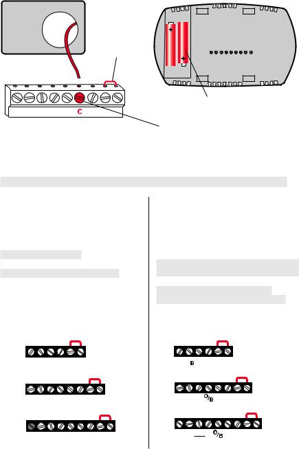
Insert batteries for primary or backup power. MCR29436
Connect C for primary AC power (optional if batteries are installed).
Wiring terminal designations
Shaded areas below apply only to
Conventional Terminals:
Rc 24VAC power from cooling transformer
R24VAC power from heating transformer
W Heat relay (stage 1) W2 Heat relay (stage 2)
Y Compressor contactor (stage 1) Y2 Compressor contactor (stage 2) G Fan relay
C24VAC common. For 2 transformer systems, use common wire from cooling transformer.
TH6110D
G W C Y R Rc
TH6220D
Y2 W2 G W C Y R Rc
TH6320U
Y2 W2 G W C Y R Rc
MCR29437A
TH6320U/TH6220D or as otherwise noted.
Heat Pump Terminals:
Rc 24VAC power from cooling transformer
R24VAC power from heating transformer
O/B Changeover valve
Y Compressor contactor
Y2 Compressor contactor (stage 2) -TH6320U only
G Fan relay
Aux/E Auxiliary/Emergency heat relay
L Sends output when set to Em. Heat C 24VAC common
TH6110D
G  C Y R Rc
TH6220D
Aux
E
TH6320U
E MCR29438A
2
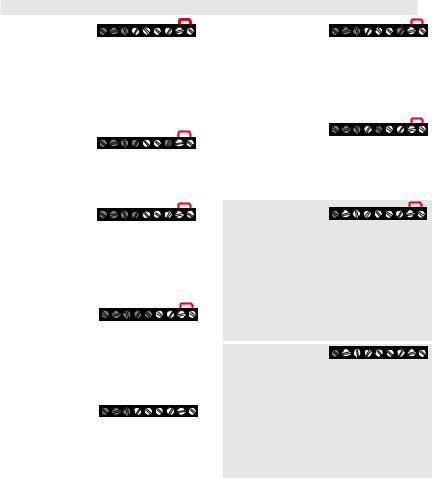
Wiring conventional systems
Shaded areas below apply only to TH6320U/TH6220D or as otherwise noted.
1H/1C System |
|
Heat-only System |
|
||
(1 transformer) |
G W C Y R Rc |
with Fan |
G W C R Rc |
||
Rc |
Power [1] |
|
Rc |
Power [1] |
|
R |
[R+Rc joined by jumper] |
R |
[R+Rc joined by jumper] |
||
Y |
Compressor contactor |
|
C |
24VAC common [3] |
|
C |
24VAC common [3] |
|
W |
Heat relay |
|
W |
Heat relay |
|
G |
Fan relay |
|
G |
Fan relay |
|
Cool-only System |
|
|
Heat-only System |
|
Rc |
Power [1] |
G C Y R Rc |
|
Rc |
Power [1] |
W C R Rc |
R |
[R+Rc joined by jumper] |
|
R |
[R+Rc joined by jumper] |
Y |
Compressor contactor |
|
|
C |
24VAC common [3] |
|
C |
24VAC common [3] |
|
W |
Heat relay |
|
G |
Fan relay |
|
Heat-only System |
|
|
(Series 20) [5] |
W C Y R Rc |
|
Rc |
[R+Rc joined by jumper] |
|
R |
Series 20 valve terminal “R” [1] |
|
Y |
Series 20 valve terminal “W” |
|
C |
24VAC common [3] |
|
W |
Series 20 valve terminal “B” |
|
Heat-only System |
|
|
(normally open zone |
C Y R Rc |
|
valve) [5] |
|
|
Rc |
[R+Rc joined by jumper] |
|
R |
Power [1] |
|
Y |
Normally open zone valve |
|
C |
24VAC common [3] |
|
1H/1C System |
|
|
(2 transformers) |
G W C Y R Rc |
|
Rc |
Power (cooling transformer) [1, 2] |
|
R |
Power (heating transformer) [1, 2] |
|
Y |
Compressor contactor |
|
C |
24VAC common [3, 4] |
|
W |
Heat relay |
|
G |
Fan relay |
|
2H/2C System |
|
|
(1 transformer) [6] |
Y2 W2 G W C Y R Rc |
|
Rc |
Power [1] |
|
R |
[R+Rc joined by jumper] |
|
Y |
Compressor contactor (stage 1) |
|
C |
24VAC common [3] |
|
W |
Heat relay (stage 1) |
|
G |
Fan relay |
|
W2 |
Heat relay (stage 2) |
|
Y2 |
Compressor contactor (stage 2) |
|
2H/2C System |
|
|
(2 transformers) [6] |
Y2 W2G W C Y R Rc |
|
Rc |
Power (cooling transformer) [1, 2] |
|
R |
Power (heating transformer) [1, 2] |
|
Y |
Compressor contactor (stage 1) |
|
C |
24VAC common [3, 4] |
|
W |
Heat relay (stage 1) |
|
G |
Fan relay |
|
W2 |
Heat relay (stage 2) |
|
Y2 |
Compressor contactor (stage 2) |
|
NOTES
Wire specifications:
Use 18to 22-gauge thermostat wire. Shielded cable is not required.
[1]Power supply. Provide disconnect means and overload protection as required.
[2]Remove jumper for 2-transformer systems.
[3]Optional 24VAC common connection.
[4]Common connection must come from cooling transformer.
[5]In Installer Setup, set system type to Heat Only.
[6]In Installer Setup, set system type to 2Heat/2Cool Conventional.
[7]In Installer Setup, set changeover valve to O or B.
[8]In Installer Setup, set system type to 2Heat/1Cool Heat Pump.
[9]In Installer Setup, set system type to 2Heat/2Cool Heat Pump.
[10] In Installer Setup, set system type to 3Heat/2Cool Heat Pump.
[11] L terminal sends a continuous output when thermostat is set to Em. Heat. Connect
to Honeywell zoning panels to switch the panel to Emergency Heat.
3
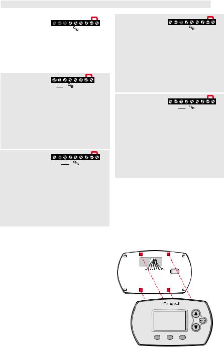
Wiring heat pump systems
Shaded areas below apply only to TH6320U/TH6220D or as otherwise noted.
1H/1C Heat Pump
System
|
M29381 |
Rc |
Power [1] |
R |
[R+Rc joined by jumper] |
Y |
Compressor contactor |
C |
24VAC common [3] |
O/B |
Changeover valve [7] |
G |
Fan relay |
2H/1C Heat Pump |
|
|
System (TH6220D |
|
|
only) [8] |
E |
|
Rc |
Power [1] |
|
R |
[R+Rc joined by jumper] |
|
Y |
Compressor contactor |
|
C |
24VAC common [3] |
|
O/B |
Changeover valve [7] |
|
G |
Fan relay |
|
Aux/E |
Auxiliary/Emergency heat relay |
|
L |
Sends output when set to Em. Heat [11] |
|
2H/1C Heat Pump |
|
|
System (TH6320U |
|
|
only) [8] |
E |
|
Rc |
Power [1] |
|
R |
[R+Rc joined by jumper] |
|
Y |
Compressor contactor |
|
C |
24VAC common [3] |
|
O/B |
Changeover valve [7] |
|
G |
Fan relay |
|
Aux/E |
Auxiliary/Emergency heat relay |
|
L |
Sends output when set to Em. Heat [11] |
|
2H/2C Heat Pump System (TH6320U only) [9]
Rc |
Power [1] |
R |
[R+Rc joined by jumper] |
Y |
Compressor contactor (stage 1) |
C |
24VAC common [3] |
O/B |
Changeover valve [7] |
G |
Fan relay |
Y2 |
Compressor contactor (stage 2) |
L |
Sends output when set to Em. Heat [11] |
3H/2C Heat Pump |
|
|
System (TH6320U |
Y2 E |
|
only) [10] |
||
Rc |
Power [1] |
|
R |
[R+Rc joined by jumper] |
|
Y |
Compressor contactor (stage 1) |
|
C |
24VAC common [3] |
|
O/B |
Changeover valve [7] |
|
G |
Fan relay |
|
Aux/E |
Auxiliary/Emergency heat relay |
|
Y2 |
Compressor contactor (stage 2) |
|
L |
Sends output when set to Em. Heat [11] |
|
See Notes on page 3.
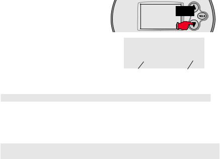
Thermostat mounting
1.Push excess wire back into the 


 wall opening.
2.Plug wall opening with nonflammable insulation.
3.Align the 4 tabs on the wallplate
with corresponding slots on the back of the thermostat.
4. Push gently until the thermostat snaps in place.
MCR29453
4

Installer setup
Follow the procedure below to configure the thermostat to match the installed heating/cooling system, and customize feature operation as desired.
1.To begin, press and hold the σ
and FAN buttons until the display changes.
2.Press σ or τ to change settings.
3.Press NEXT to advance to next function.
4.Press DONE to exit and save settings.
1 |
0 |
Done |
Next |
Function |
MCR29454 |
Setting |
|
number |
|
Setup function |
Settings & options (factory default in bold) |
Shaded areas below apply only to TH6320U/TH6220D or as otherwise noted.
1 |
System type |
0 |
1 heat/1 cool conventional |
|
|
1 |
1 heat/1 cool heat pump (no aux. heat) |
|
|
2 |
Heat only — 2-wire systems, 3-wire zone valves (Series 20), |
|
|
|
and normally open zone valves |
|
|
3 |
Heat only with fan |
|
|
4 |
Cool only |
|
|
5 |
2 heat/1 cool heat pump (with aux. heat) |
|
|
6 |
2 heat/2 cool conventional |
|
|
7 |
2 heat/1 cool conventional |
|
|
8 |
1 heat/2 cool conventional |
|
|
9 |
2 heat/2 cool heat pump (no aux. heat) - TH6320U only |
|
|
10 |
3 heat/2 cool heat pump (with aux. heat) - TH6320U only |
2 |
Changeover valve |
0 |
Changeover valve (O/B terminal energized in cooling) |
|
(O/B terminal) |
1 |
Changeover valve (O/B terminal energized in heating) |
3 |
Fan control |
0 |
Gas or oil furnace — equipment controls fan in heating |
|
(heating) |
1 |
Electric furnace — thermostat controls fan in heating |
5 |
Stage 1 heat cycle |
5 |
For gas or oil furnaces of less than 90% efficiency |
|
rate |
1 |
For steam or gravity systems |
|
(CPH: cycles/hour)* |
3 |
For hot water systems & furnaces of over 90% efficiency |
|
|
9 |
For electric furnaces |
6 |
Stage 2 heat cycle |
5 |
For gas or oil furnaces of less than 90% efficiency |
|
rate/Auxiliary heat |
1 |
For steam or gravity systems |
|
cycle rate (CPH)* |
3 |
For hot water systems & furnaces of over 90% efficiency |
|
|
9 |
For electric furnaces |
7 |
Auxiliary heat |
5 |
For gas or oil furnaces of less than 90% efficiency |
|
cycle rate (CPH)* |
1 |
For steam or gravity systems |
|
Only TH6320U |
3 |
For hot water systems & furnaces of over 90% efficiency |
|
9 |
For electric furnaces |
|
|
for 3H/2C Heat |
Pumps
*[Other cycle rate options: 2, 4, 6, 7, 8, 10, 11 or 12 CPH]
5

Setup function |
Settings & options (factory default in bold) |
Shaded areas below apply only to TH6320U/TH6220D or as otherwise noted.
9 |
Stage 1 compressor |
3 |
Recommended for most compressors |
|
cycle rate (CPH) |
|
[Other cycle rate options: 1, 2, 4, 5 or 6 CPH] |
10 |
Stage 2 compressor |
3 |
Recommended for most compressors |
|
cycle rate (CPH) |
|
[Other cycle rate options: 1, 2, 4, 5 or 6 CPH] |
12 |
Manual/Auto |
0 |
Manual changeover (Heat/Cool/Off) |
|
changeover |
1 |
Auto changeover (Heat/Cool/Auto/Off) |
|
|
2 |
Auto changeover only (Auto) |
13 |
Adaptive Intelligent |
1 |
On**See page 8 |
|
Recovery™ |
0 |
Off |
14 |
Temperature |
0 |
Fahrenheit |
|
display |
1 |
Celsius |
15 |
Compressor |
5 |
Five-minute compressor off time |
|
protection |
|
[Other options: 0, 1, 2, 3 or 4-minute off time] |
16 |
Schedule format |
0 |
5/2 (programmable weekdays and weekends) |
|
|
1 |
5/1/1 (weekdays, Saturday & Sunday programmable) |
26 |
Auxiliary heat |
0 |
Comfort |
|
control |
1 |
Economy |
27 |
Heat temperature |
90 |
Max. heat temperature setting is 90 °F (32 °C) |
|
range stops |
|
[Other options: 40 °F to 89 °F (4.5 °C to 31.5 °C)] |
28 |
Cool temperature |
50 |
Min. cool temperature setting is 50 °F (10 °C) |
|
range stops |
|
[Other options: 51 °F to 99 °F (10.5 °C to 37 °C)] |
Special function
Auto Changeover (Setup Function 12): When set to Auto, the thermostat automatically selects heating or cooling depending on the indoor temperature. The thermostat will automatically adjust heat and cool settings to maintain
a 3-degree separation (fixed). Note: If you select Auto Changeover Only, the System Setting on the thermostat will stay locked in the Auto position, preventing the user from changing it to Em Heat, Heat, Cool or Off.
Adaptive Intelligent Recovery™ (Setup Function 13): Allows the thermostat to “learn” how long the furnace and air conditioner take to reach programmed temperature settings, so the temperature is reached at the scheduled time.
Compressor Protection (Setup Function 15): Forces the compressor to wait a few minutes before restarting, to prevent damage. During the wait time, the message Cool On or Heat On (heat pumps only) will flash on the display.
6
Installer system test
1.To begin, press and hold the σ and τ buttons until the display changes.
2.Press σ / τ to turn system on/off.
3.Press NEXT to advance to next test
4.Press DONE to terminate system test.
System test |
System status |
10 |
0 |
System test |
System |
|
MCR29455 |
number |
status |
Shaded areas below apply only to TH6320U/TH6220D or as otherwise noted.
10 |
Heating system |
0 |
Heat and fan turn off. |
|
|
1 |
Stage 1 heat turns on. Fan turns on if Setup Function 1 is |
|
|
|
set to 1, 5, 9 or 10 OR Setup Function 3 is set to 1 |
|
|
2 |
Stage 2 heat turns on |
|
|
3 |
Stage 3 heat turns on - TH6320U only |
20 |
Emergency heating |
0 |
Heat and fan turn off |
|
system |
1 |
Heat and fan turn on |
30 |
Cooling system |
0 |
Compressor and fan turn off |
|
|
1 |
Compressor and fan turn on |
|
|
2 |
Stage 2 compressor turns on |
40 |
Fan system |
0 |
Fan turns off |
|
|
1 |
Fan turns on |
Specifications
Temperature Ranges |
Electrical Ratings |
|
|
Heat: 40° to 90°F (4.5° to 32°C) |
Terminal |
Voltage (50/60Hz) |
Running Current |
Cool: 50° to 99°F (10° to 37°C) |
W Heating |
20-30 Vac |
0.02-1.0 A |
Operating Ambient Temperature |
(Powerpile) |
750 mV DC |
100 mA DC |
32° to 120°F (0° to 48.9°C) |
W2 (Aux/E) Heating |
20-30 Vac |
0.02-1.0 A |
Shipping Temperature |
Y Cooling |
20-30 Vac |
0.02-1.0 A |
-20° to 120°F (-28.9° to 48.9°C) |
Y2 Cooling |
20-30 Vac |
0.02-1.0 A |
Operating Relative Humidity |
G Fan |
20-30 Vac |
0.02-0.5 A |
5% to 90% (non-condensing) |
O/B Changeover |
20-30 Vac |
0.02-0.5 A |
Physical Dimensions |
L Output |
20-30 Vac |
0.02-0.5 A |
3-9/16” H x 5-13/16” W x 1-1/2” D |
|
|
|
91 mm H x 147 mm W x 38 mm D |
|
|
|
7
Customer assistance
For assistance with this product, please visit customer.honeywell.com.
Or call Honeywell Customer Care tollfree at 1-800-468-1502.
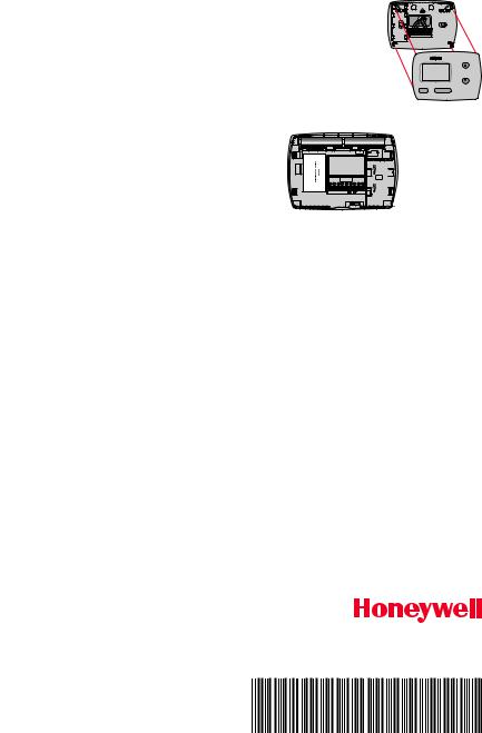
Pull at bottom to remove thermostat from wallplate.
Turn thermostat over to find model number and date code.
CAUTION:
EQUIPMENT DAMAGE HAZARD
Compressor protection is bypassed during testing. To prevent equipment damage, avoid cycling the compressor quickly.
CAUTION: ELECTRICAL HAZARD
Can cause electrical shock or equipment damage. Disconnect power before beginning installation.
CAUTION: MERCURY NOTICE
If this product is replacing a control that contains mercury in a sealed tube, do not place the old control in the trash. Contact your local waste management authority for instructions regarding recycling and proper disposal.
Automation and Control Solutions
Honeywell International Inc.
1985 Douglas Drive North
Golden Valley, MN 55422
Honeywell Ltd |
|
705 Montrichard Avenue |
|
Saint-Jean-sur-Richelieu, Québec |
|
J2X 5K8 |
|
customer.honeywell.com |
|
® U.S. Registered Trademark. |
|
© 2014 Honeywell International Inc. |
|
69-2695EFS—05 M.S. Rev. 03-14 |
69-2695EFS-05 |
Printed in U.S.A. |
 Loading...