


R-323EX
Pentax R-323EX, R-335NX, R-322EX, R-323NX, R-315NX INSTRUCTION MANUAL
...
PENTAX Industrial Instruments Co.,Ltd.
2-36-9, Maeno-cho
Itabashi-ku, Tokyo 174-0063 Japan
Tel. +81 3 3960 0502
Fax +81 3 3960 0509
E-mail: international@piic.pentax.co.jp
Website: www.pentax.co.jp/piic/survey
www.pentaxsurveying.com
TOTAL STATION
R-300X
INSTRUCTION
MANUAL
FOR R-300X SERIES BASIC
R-315EX R-315NX
R-325EX R-325NX
R-335EX R-335NX
R-322EX R-322NX
R-323EX R-323NX
R-326EX
SERIES

Before using this product, be sure that you have thoroughly read
and understood this instruction manual to ensure proper
operation.
After reading this manual,be sure to keep in a convenient place
for easy reference.
Copyright © 2005 PENTAX Industrial Instruments Co.,Ltd.
All Rights Reserved
PENTAX Industrial Instruments Co.,Ltd.is a sole proprietor of the PTL software.
The PTL software and publication or parts thereof,may not be reproduced in any form,by any method,
for any purpose.
PENTAX Industrial Instruments Co.,Ltd.makes no warranty,expressed or implied,including but not limited to any implied warranties or merchantability or fitness for a particular purpose,regarding these
materials and makes such materials available.

3
PRECAUTIONS REGARDING SAFETY
Safety precautions (Must be followed)
The following items are intended to prevent possible injury to the user or other people
and/or damage to the instrument before it occurs. These safety precautions are important
to the safe operation of this product and should be observed at all times.
Distinctive displays
The following displays are used to distinguish precautions by the degree of injury or
damage that may result if the precaution is ignored.
WARNING
Items indicated by this display are precautions which if ignored would result in serious
injury.
CAUTION
Items indicated by this display are precautions which if ignored may result in injury or
material.
• Here “injury”refers to injuries such as cuts,burns or elec tric shock the treatment of
which will not likely require hospitalization or long-term attention.
• “Material damage”refers to damage to facilities,buildings,acquired data,etc.
Before using this product,be sure that you have thoroughly read and understood this
instruction manual to ensure proper operation.After reading this manual,be sure to keep
it in a convenient place for easy reference.
This instrument complies with the protection requirement for residential and commercial
areas.If this instrument is used close to industrial areas or transmitters,the equipment can
be influenced by electromagnetic fields.
Three R-300X Quick Reference Guide are provided in your carrying case.
They are
1. Basic Procedures,
2. Power Topo Lite Operating Procedures

4
PRECAUTIONS REGARDING SAFETY
WARNING
Do not stare into the laser beam directly as this may result in damage to your eyes.
R-300X is a Class II Laser product.(The reflectorless type is a Class IIIa (3R) laser product.)
Do not look into the laser radiation aperture directly as this may result in damage to
your eyes.
Never use the telescope to view intense light such as direct sunlight or sunlight
reflected through a prism as this may result in loss of sight.
Do not disassemble,modify or repair this product as there a risk of laser radiation.
Do not aim the laser beam at a person as it is harmful to the eyes and body.Receive
the examination treatment by the doctor when the eyesight or body trouble is doubted
by any chance.
• Electro-Magnetic Compatibility (EMC):
This instrument complies with the protection requirement for residential and
commercial areas.If this instrument is used close to industrial areas or transmitters,
the equipment can be influenced by electromagnetic fields.
• Do not use this product in a coal mine,in a location where there is coal dust,or near
flammable material as there is a risk of explosion.
• Do not disassemble,modify or repair this product as there is a risk of fire,electric
shock and burn injury.If you think the product requires repair,contact the retail
outlet where you purchased it or an authorized repair site.
• Only use the BC03 battery charger intended for this product as the battery charger.
Use of another battery charger entails a risk of fire or burn injury from the battery
bursting into flames due to possible differences in voltage or polarity.
• Do not use a damaged electric cord plug or loose electric outlet when charging as
there is a risk of fire or electric shock.
• Do not charge the battery while covered by clothes or similar item as there is a risk
of fire if the clothes ignite.
• Do not use the battery or charger when wet as there is a risk of fire and burn injury
due to short-circuit.
• To prevent making short-circuit when removing the battery and charger from the
case and storing them,apply electrically resistant tape to the poles of the battery.
Storing the battery and charger as-is may result in fire or burn injury due to
short-circuit.
• Do not throw the battery into fire or expose it to heat as there is a risk of injury if it
explodes.

5
PRECAUTIONS REGARDING SAFETY
CAUTION
For security,please do the opening inspection and inspec tion ever y a fixed period and
adjustment.
When the laser beam enters eyes,an unexpected accident might be caused by the
blink of eyes.Establish the laser product to avoid the height of eyes of a driving person
and walker.
Establish an instrument so that laser beam does not hit a reflection thing as a mirror
and a glass window.The refection beam of the laser is also harmful to the human body.
Besides the time when you measure the distance,cut off the power supply or shade
the beam of aperture with caps.
Keep the laser product in the place where the person who does not have the product
knowledge such as children does not touch by mistake.
Destroy the power supply mechanism of the instrument so as not to emit the laser
beam when throwing away it.
• Do not remove the handgrip without good reason.If it does come off,be sure to
attach it securely to the instrument with screws.If it is not fastened securely,the
instrument may fall when you grasp the handgrip,leading to possible injury.
• Do not short the poles of the battery or charger as there is a risk of injury or fire.
• Do not touch any fluid which may leak from the battery as there is a risk of chemical
burn injury or reaction.
• Do not insert or remove the electric plug with wet hands as there is a risk of electric
shock.
• Do not use the case to stand on as it is slippery and unstable and may cause you to
fall,resulting in possible injury.
• Be sure the tripod itself and the instrument on the tripod are both installed securely
as insecure installation may cause the tripod to fall over or the instrument to drop,
resulting in possible injury.
• Do not carry the tripod with the metal shoe pointing toward another person as the
person may be injured if they strike him or her.
• The instrument contains a rechargeable battery and it is rechargeable.
• At the end of its useful life,it may be illegal to dispose of the battery.
• Check with your local solid waste officials for details for recycling.

6
PRECAUTIONS REGARDING SAFETY
Usage precautions
Surveying instruments are high-precision instruments.In order to assure that the
Electronic Total Station R-300X series product which you have purchased
will provide long-lasting maximum performance,the precautions in this manual must be
followed.Be sure to follow these instructions and use this product properly at all times.
[Solar observation]
WARNING
Never view the sun directly using the telescope as this may result in loss of sight.
Never point the objective lens directly at the sun as this may damage internal
components.When using the instrument for solar observation,be sure to attach the
special solar filter (MU64) designed for this product to the objective lens.
[Laser beam]
Do not stare into laser beam.R-300X is a class-II Laser product.(The reflectorless type is
a Class IIIa (3R) laser product.)
[EDM axis]
The R-300X series EDM is the red visible laser beam and the beam diameter is very small.
The beam is emitted from the objective center and the base plate center hole.The EDM
axis is designed to coincide with the telescope sight axis but both axes may not
sometimes coincide slightly according to the intense temperature change and time lapse.
[Target constant]
Confirm the Target Constant of the instrument before measurement.
If a different constant is to be used,use the correct constant of the target.The constant is
stored in the instrument's memory when turned off.
[Reflectorless and reflector sheet]
• Reflectorless:
The measurement range and accuracy of Reflectorless are based on the condition that
laser beam is emitted perpendicular to the white side of the Kodak Gray Card.
The measurement range may be influenced by the shape of the target and its
environment.There is a possibility that the range may vary when the target does not
satisfy the conditions above at survey work.
• Pay attention to following in case of distance measurement by Reflectorless.
In a situation resulting in low accuracy,perform the distance measurement by
Reflector sheet or Prism.(R-315NX,R-325NX,R-335NX,R-322NX, R-323NX)
• There is a possibility that correct distance measurement may be impossible by
dispersion or reduction of laser beam when the laser beam comes into the target from
diagonal angle.

7
PRECAUTIONS REGARDING SAFETY
• There is a possibility that the instrument cannot calculate correctly when receiving
reflected laser beam from forth and back directions in case of measuring the target on
the road.
• There is a possibility that synthesized values are calculated and the distance may
become longer or shorter than the actual one when the operator measure the target
of slope or sphere or rugged shape.
• There is a possibility that the instrument cannot calculate correctly by collecting the
reflected laser beam from a man or a car that comes and goes in front of the target.
• When using reflector sheet,set the reflector sheet to have its surface be approx.
vertical to the aiming line.If it is positioned not to be approx.right angle,there is a
possibility that correct distance measurement may be impossible by dispersion or
reduction of laser beam.
In the following environments,the distance might not be able to be measured.
There is a reflection things (mirror, stainless board and white wall, etc.) in the direction
of the target and under too strong sun light.
[Battery & charger]
• Never use any battery charger other than the BC03 battery charger as this may
result in damage to the instrument.
• If water should happen to splash on the instrument or the battery,wipe it off
immediately and allow it to dry in a dry location.Do not put the instrument in the
case until it is completely dry as this may result in damage to the instrument.
• Turn off the power when removing the battery from the instrument as removing
the battery while the power is still on may result in damage to the instrument.
• The battery mark displayed on the instrument is only an estimate of remaining
battery power and is not completely accurate.Replace the battery quickly when it is
about to run down as the time a battery lasts on one charge differs depending on
conditions of ambient temperature,and the measurement mode of the instrument.
• Confirm the battery level remaining before operating.
[Auto focus]
The Auto focus mechanism is very precise but will not function under every condition.
Focusing depends on brightness,contrast,the shape and size of the target.
In such a case,press the AF button and focus on the target by operating the Power focus
key or the AF ring.
[LD POINT,laser pointer]
When you make a correct direction using the “LD POINT”,aim the laser beam at the wall and
mark the center and then confirm the discrepancy between the reticle center and the
marked point beforehand.

8
PRECAUTIONS REGARDING SAFETY
[Storage and operating environment]
• To prevent making short-circuit when removing the battery and charger from the case
and storing them,apply electrically resistant tape to the poles of the battery.Storing the
battery and charger as is may result in fire or burn injury due to short-circuit.
• Avoid storing the instrument in places subject to extreme high,low or radically fluctuating
temperature.(Ambient temperature range during use:–20° C to +50° C)
• Distance measurements may take longer when atmospheric conditions are poor such
as when heat shimmer is present.When storing the instrument,always put it in its case
and avoid storage in dusty location or location subject to vibration or extreme heat or
humidity.
• Whenever there is a sharp temperature difference between the instrument’s storage and
usage locations allow the instrument to adjust to the ambient for an hour or more before
use.Be sure to protect the instrument from the sun if the location is subject to intense
direct sunlight.
• During surveys for which the survey precision or atmospheric measurement method has
been defined measure the atmospheric temperature and pressure separately and enter
those values rather than using the Automatic Atmospheric Correction function.
• The battery should be charged approximately once per month if the instrument is to be
stored for an extended period of time. The instrument should also be removed from its
case occasionally and aired out.
• In addition to these precautions,be sure to handle the instrument properly at all times
following the descriptions given in the various sections of this manual to assure safe and
proper measurements.
[Transporting and carrying the instrument]
• Be careful to protect this instrument from shock of impact and excessive vibration which
may result in damage during transportation and shipment.
• When transporting the instrument,always put it in the case and wrap shockabsorbing
material around it and be sure it is handled as “FRAGILE”.
[Checks and repairs]
• Always check the instrument before beginning work and check that the instrument is
maintaining the proper level of precision.Pentax bears absolutely no responsibility for
damages due to survey results obtained from surveys conducted without an initial
instrument check.
• Never disassemble the instrument,battery or charger even if you do detect an
abnormality as there is a risk of fire or electric shock due to short-circuit.If you think the
product requires repair, contac t the retail outlet where you purchased it or an authorized
repair site.

9
CONTENTS
PRECAUTIONS REGARDING SAFETY 3
SAFETY PRECAUTIONS (MUST BE FOLLOWED) 3
USAGE PRECAUTIONS 6
1.BEFORE USING THE INSTRUMENT 12
1.1 NAMES OF PARTS 12
1.2 UNPACKING AND PACKING 14
1.3 STANDARD EQUIPMENT 14
1.4 ATTACHING AND CHARGING THE BATTERY 15
2.DISPLAY AND KEYBOARD 18
2.1 DISPLAY AND KEYBOARD 18
2.2 OPERATION KEY 18
2.3 FUNCTION KEY 19
2.4 ALPHANUMERIC INPUT 21
2.5 LD POINT,LASER POINTER 21
3.PREPARATION FOR SURVEYING 22
3.1 CENTERING AND LEVELING OF THE INSTRUMENT 22
3.2 LASER PLUMMET 23
3.3 OPTICAL PLUMMET (OPTION) 24
3.4 LEVELING WITH CIRCULAR VIAL 25
3.5 LEVELING WITH ELECTRONIC VIAL 25
3.6 EYEPIECE ADJUSTMENT 27
3.7 TARGET SIGHTING 27
3.8 ATTACHMENT AND DETACHMENT OF TRIBRACH 31
4.TURNING THE POWER ON 32
4.1 TURNING THE POWER ON AND OFF 32
4.2 ADJUSTING LCD CONTRAST 33
4.3 ADJUSTING ILLUMINATION BRIGHTNESS 33
4.4 ADJUSTING RETICLE ILLUMINATION 34
5.ANGLE MEASUREMENT 35
5.1 MEASURING AN ANGLE 35
5.2 RESETTING THE HORIZONTAL ANGLE TO 0 35
5.3 HOLDING THE HORIZONTAL ANGLE 36
5.4 INPUTTING AN ARBITRARY HORIZONTAL ANGLE 36
5.5 DISPLAYING THE % SLOPE OF THE VERTICAL ANGLE 47
5.6 CHANGING THE HORIZONTAL ANGLE FROM
CLOCKWISE TO COUNTERCLOCKWISE 38

10
6.DISTANCE MEASUREMENT 39
6.1 TARGET SETTING 39
6.2 DISTANCE MEASUREMENT 41
6.3 QUICK MODE 42
7.CORRECTION MODE 43
7.1 CHANGING THE TARGET CONST ANT 43
7.2 CHANGING THE TEMPERATURE 44
7.3 CHANGING THE ATMOSPHERIC PRESSURE 45
7.4 CHANGING THE PPM VALUE 46
8.INITIAL SET TING 48
8.1 OVERVIEW 48
8.2 ENTERING THE MODE FOR INITIAL SETTING 1 48
8.3 ENTERING THE MODE FOR INITIAL SETTING 2 49
8.4 ENTERING THE MODE FOR INITIAL SETTING 4 49
8.5 ENTERING THE MODE FOR INITIAL SETTING 5 49
8.6 SETTING OF [DATE AND TIME] 50
8.7 EXAMPLE OF CHANGING AN INITIAL SETTING CONTENT
(SELECTION OF ATMOSPHERIC CORRECTION) 50
8.8 INITIAL SETTING 1 50
8.9 INITIAL SETTING 2 51
8.10 INITIAL SETTING 4 55
8.11 INITIAL SETTING 5 55
8.12 INITIAL SETTING OF DATE AND TIME 56
9.ACCESSING THE FUNCTIONS 57
9.1 ACCESSING BY HELP KEY 57
9.2 ACCESSING BY 007 57
10.CHECKS AND ADJUSTMENTS 59
10.1 ELECTRONIC VIAL 59
10.2 CIRCULAR VIAL 60
10.3 VERTICAL RETICLE 61
10.4 PERPENDICULARITY OF LINE OF SIGHT TO HORIZONTAL AXIS 62
10.5 VERTICAL 0 POINT ERROR 63
10.6 LASER PLUMMET 63
10.7 OPTICAL PLUMMET 64
10.8 OFFSET CONSTANT 65
10.9 BEAM AXIS AND LINE OF SIGHT 65
10.10 THE EDM BEAM AXIS 66
11.SPECIFICATIONS 67
12.DATA COLLECTOR 69

11
13.APPENDIX 70
13.1 ERROR MESSAGES 70
13.2 ATMOSPHERIC CORRECTION 71
13.3 HPA AND MMHG CONVERSION TABLE 72
13.4 ERROR WHEN NO ATMOSPHERIC CORRECTION IS MADE 72
13.5 ATMOSPHERIC REFRACTION AND EARTH CURVATURE CORRECTION 73
13.6 DISTANCE RANGE 74
14.NOTICE TO THE USER OF THIS PRODUCT 75
12
1.BEFORE USING THE INSTRUMENT
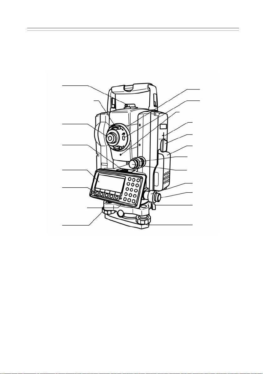
1.1 Names of parts
R-325EX(NX)/ R-322EX(NX)/ R-323EX(NX):Detachable t ype
Collimator
Power focus key
Focusing knob
AF button
Laser indicator
Instrument height mark
Battery latch
Battery pack
Telescope tangent screw
Telescope clamp screw
Clamp screw
Tangent screw
Detaching knob
Base plate
Eyepiece
Circular vial
Display panel
Key board
Circular vial
Leveling screw
13
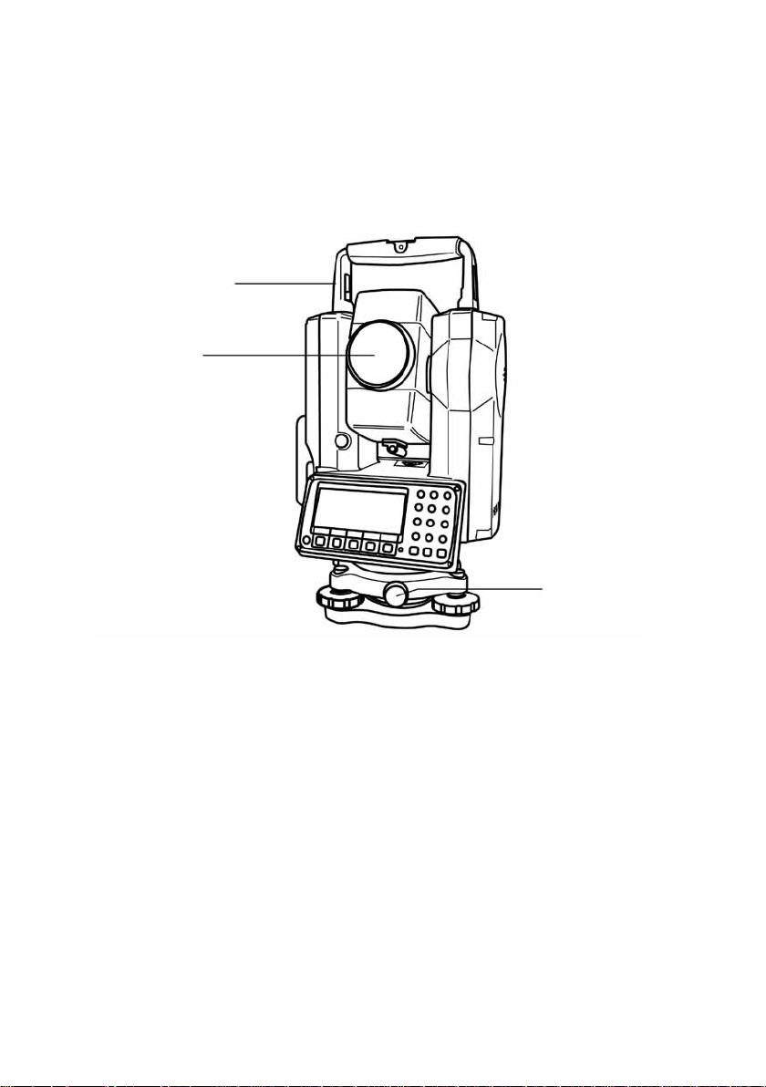
R-335EX (NX):Shif t type
• Dual display panel is an optional accessory.
Top handle
Objective lens
Centering knob

14
1.2 Unpacking and packing
[Unpacking the Instrument from the case]
Set the case down gently with the lid facing upwards.
Open the latches while pressing down on the lock (safety mechanism) and open the
lid of the case.
Remove the instrument from the case.
[Packing the instrument in the case]
Make sure the telescope is fairly level and lightly tighten the telescope clamp screw.
Line up the housing marks (round yellow marks on the instrument) and tighten the
upper and lower clamp screws.
With the housing marks facing upward,set the instrument gently in the case without
forcing it.
Close the lid to the case and secure the latches.
1.3 Standard equipment
Instrument
Carrying case
BP02 battery
BC03/AC01 charger
Plumb bob
Hexagonal wrench
Rain cover
Quick Reference Guide (Basic,PTL procedures)
CD-R (Basic operation & Special Functions manual)
9
8
7
6
5
4
3
2
1
4
3
2
1
3
2
1

15
1.4 Attaching and charging the battery
[Removing the battery]
Turn the lock lever anticlockwise and remove the battery.
Lift up the battery pack and remove it from the instrument.
• Be absolutely sure to turn the power off when removing the battery as removing the
battery while the power is still on may result in damage to the instrument.
[Attaching the battery]
Align the guide grooves on the battery pack with the guide grooves on the instrument
and push the top of the battery pack into place.
Turn the lock lever clockwise to fix.
[Remaining battery charge]
When the instrument’s power is turned on,a battery mark “ ”will be displayed on the
right of the display screen.This mark can be used to check the charge status of the battery.
Low battery:Please change.Replace with the spare battery or charge.
2
1
2
1
Plenty of charge left
Get the spare battery ready
Replace with the spare battery
1
2
1
3
2

16
[Charging the battery]
• The battery BP02 is not charged at our factory shipment so charge it.
• For BP02 charge,use the special BC03 charger.
Power supply cord
AC adaptor Charger
[Connection of code]
Insert the output plug of the power supply code in Jack of the AC adaptor.
Insert the output plug of the AC adaptor in Jack of the charger.
Insert the power supply plug of the power supply code in the outlet of AC power supply.
[Installation of battery]
Draw the battery to the lock lever side and put it on the battery pocket.The battery is
firmly installed on the battery pocket.
Press down the battery and then slide it to the opposite direction of the lock lever.
The lock lever goes up,and the battery is fixed.
Under such a condition,if “Connection of the code”is done,the charge with the batter y
is begun.
[Detaching the battery]
Press the lock lever and slide the battery to the lock lever direction.
Detach the battery packing from the battery pocket.
[Display panel]
2
1
4
3
2
1
3
2
1
Installation lamp
Charge lamp
Power lamp
Discharge lamp
Discharg button
Lock lever
Battery
Battery pocket
Charger
4
2
1
5
3

17
Power supply lamp (red) : Turns on when the power supply is turned on.
Charge lamp (green):Turns on while charging and turns off when the charge is
completed.
Discharge lamp (yellow):Turns on when you push the discharge button.
Turns off when the discharge is completed.
Installation lamp (red):Blinks or turns on when the battery pack ing is attached normally.
Blinks when charge or discharge and turns on when charge is completed.
(The charge lamp in the lower does not blink and does not turns on)
Discharge button:Discharge lamp lights when you push this button,and the discharge
of battery begins.
[How to charge]
It begins charging automatically when you set the battery packing in the charger
which beams the power supply lamp.
Leave just as it is until the charge is completed.
When the charge is completed,the charge lamp is turned off.
Detach the battery packing from the charger when the charge is completed.
[Refreshing the battery]
The use time shortens gradually by the phenomenon of “Effect of the memory”when the
NiMH battery leaves capacity and repeats the charge.The voltage recovers after
refreshing and the use time returns normally in such a battery.Please refresh one degree
every five times of the charge.
[Refreshing]
Set the battery in the charger as well as the case of the charge.Push the electrical
discharge button.The electrical discharge lamp lights and the electrical discharge begins.
The electrical discharge lamp is turned off when the electrical discharge ends,the charge
lamp lights,and the charge starts automatically.Leave just as it is until the charge is
completed. When the charge is completed,the charge lamp is turned off.Detach the
battery from the charger.
[Time of refreshing and charge]
Battery BP02 is discharged from the state of a full charge at about 960 minutes and the
charge is completed from the electrical discharge at about 130 minutes.However, the
electrical discharge time is proportional to the remainder capacity of the battery.
Moreover,the time required for refreshing might be different from the above-mentioned
time according to a surrounding temperature and the state of the battery.
4
3
2
1
5
4
3
2
1
18
2.DISPLAY AND KEYBOARD
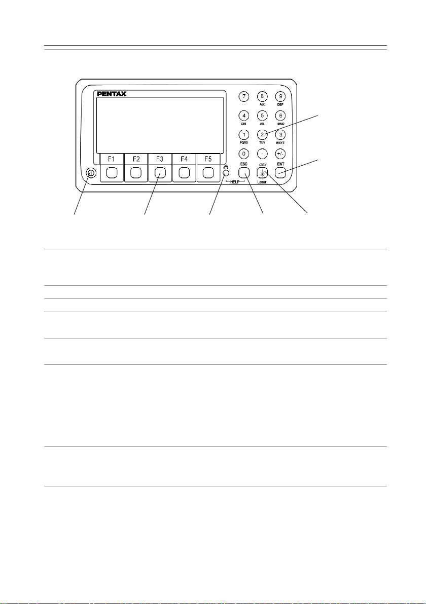
2.1 Display and keyboard
2.2 Operation key
Key Description
[POWER] ON/OFF of power supply
[ESC] Returns to previous screen or cancels an operation.
[ILLU] Turns the illumination of the LCD display and telescope reticle on
and off.
[ENT] Accepts the selected (highlighted) choice or the displayed screen
value.
[LASER] Displays the laser plummet *1,electronic vial function, and the
LD point screen when you push the laser plummet/electronic vial
key.
(Refer to “2-5 Laser Pointer”, “3-2 Laser plummet”, and “3-5 Leveling
with Electronic vial”).
*1:Only the product with the laser plummet func tion
[Alphanumeric] At the numerical value screen,the numerical value and the sign “.”
displayed are input. The English characters printed right under
numeric of each key are input.
[HELP] Pressing [lLLU]+[ESC] key causes a help menu to appear in
A MODE or B MODE or causes a help message to appear.
Alphanumeric
and +/- key
Enter key
Power supply key Function key Illumination key ESC key Laser plummet and
Electronic vial key

19
2.3 Function Key
Display F.Key Description
MODE A
[MEAS] F1 Pressing this key one time measures the distance in
normal mode another measurement type can be selected
by Initial Setting 2.Pressing this key twice measures the
distance in coarse mode another measurement type can
be selected by Initial Setting 2.
[TARGET] F2 Select the target type by following order.
SHEET/ REFRECTORLESS /PRISM
(Reflectorless type instrument)
SHEET/PRISM
(Prism type instrument)
[0 SET] F3 Resets the horizontal angle to 0° 0’0”by pressing twice.
[DISP] F4 Switches the display composition in the order
“H.angle/H.dst./V.dst.”, “H.angle/V.angle/S.dst.”and
“H.angle/V.angle/H.dst./S.dst./V.dst.”
[MODE] F5 Switches the screen between MODE A and MODE B.
MODE B
[S.FUNC] F1 PowerTopoLite
[ANG SET] F2 Brings up the angle setting screen for setting angle-related
parameters
(H.ANGLE/%GRADE,H.ANGLE INPUT and R/L REVERSE).
[HOLD] F3 Pressing this key twice retains (holds) the horizontal angle
shown on the display.
[CORR] F4 Brings up the screen for changing the target constant,
temperature.
Pressure setting.
[MODE] F5 Switches the screen between MODE A and MODE B.

20
Other functions
[] F1 Moves the cursor to the left.
[] F2 Moves the cursor to the right.
[] F1 Goes back five items on the screen.
[] F2 Goes forward five items on the screen.
[RETICLE] F3 Changing the reticle illumination when pressing
illumination key.
[] F3 Moves the cursor up.
[LCD] F4 Changing the LCD contrast when pressing illumination
key.
[] F4 Moves the cursor down.
[ILLU] F5 Changing the LCD illumination when pressing
illumination key.
[CLEAR] F5 Clear the figure.
[SELECT] F5 Open the selection window.
[How to move the menu number]
Example:
The cursor is located at Menu 1.
Press the numeric key 0 and 2 to
move to Menu 2 or press [F4] [ ].
1.ANGLE / %GRADE:ANGLE
2.H.ANGLE INPUT:092 30’20”
3.R/L REVERSE:RIGHT
SELECT
1.ANGLE / %GRADE:ANGLE
2.H.ANGLE INPUT:092 30’20”
3.R/L REVERSE:RIGHT
SELECT
ANGLE SET
ANGLESET

21
2.4 Alphanumeric input
The point name is inputted by the alphanumeric keys as following.
Key Letter under key Letter & figure order to input
[0] [@][.][_][-][:][/][0]
[1] PQRS [P][Q][R][S][p][q][r][s][1]
[2] TUV [T][U][V][t][u][v][2]
[3] WXYZ [W][X][Y][Z][w][x][y][z][3]
[4] GHI [G][H][I][g][h][i][4]
[5] JKL [J][K][L][j][k][l][5]
[6] MNO [M][N][O][m][n][o][6]
[7] [??][?][!][_][ ][^][|][&][7]
[8] ABC [A][B][C][a][b][c][8]
[9] DEF [D][E][F][d][e][f][9]
[.] [.][,][:][;][#][(][)]
[+/-] [+][-][*][/][%][=][<][>]
2.5 LD POINT,laser pointer
The Laser pointer function turns the laser beam on continuously to become the aiming
point so that visual confirmation is possible.
When the [LD POINT ] key is pressed after pressing the [Laser] key,the Laser pointer
function is turned on.The Laser indicator is turned on and the “ ”mark on the left of
the screen blinks while the Laser pointer function is operating.
If the [Laser] key is pressed and the [LD POINT ] key is pressed while the Laser pointer
function is operating,the Laser pointer function is turned off.
• The beam of the sun is strong and visual confirmation is difficult in daytime when out
doors.
• The laser beam is designed not to be able to observe through the telescope.
• Please visually align the laser beam to the target and mark the center.
Confirm the alignment (horizontal and vertical ) before measuring when performing
accurate work like stake out when using the Laser pointer function.
Also refer to 10-10.The EDM beam axis.
• Please do not look at the laser source of beam directly.
2
1
22
3.PREPARATION FOR SURVEYING
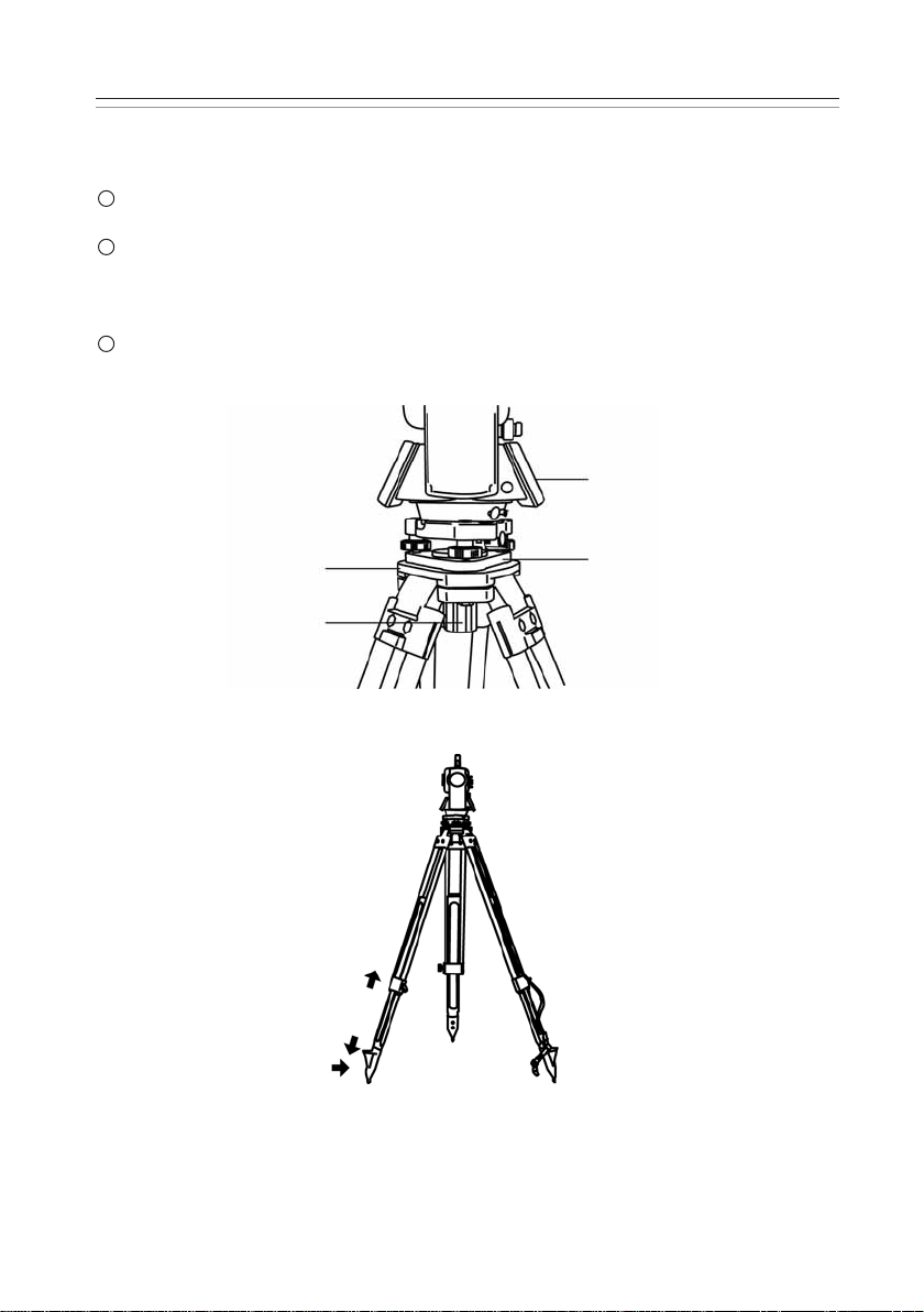
3.1 Centering and leveling of the instrument
[Setting up the instrument and the tripod]
Adjust the tripod legs so that a height suitable for observation is obtained when the
instrument is set on the tripod.
Hang the plumb bob on the hook of the tripod,and coarse center over the station on
the ground.At this time,set the tripod and fix the metal shoes firmly into the ground
so that the tripod head is as level as possible,and the plumb bob coincides with the
station on the ground.
If the tripod head is mis-leveled by the action of fixing the metal shoes into the
ground,correct the level by extending or retracting each leg of the tripod.
3
2
1
Instrument
Base plate
Tripod head
Center screw
Metal shoe
Contract
23
3.2 Laser plummet
[Laser plummet model]
The laser plummet is not set to be ON at factory shipping.The laser plummet operation of
power supply ON can be set by command No 520,LD PLUM & E VIAL.For using Command
number,refer to 9-2.Accessing by 007.
[For the Detaching type laser plummet equipment model]
Turn on the laser plummet function by pushing the Laser key.
Match the position with the leveling screw so that the laser mark coincides with the
ground mark.
[For the Shift type laser plummet equipment model]
• Turn on the laser plummet function by pushing the Laser key.
• Match the position by the tripod so that the laser mark coincides with the ground mark.
• The centering knob is loosened,and the upper plate is pushed by the tip of a finger,
and a center mark is matched to the ground mark.
• Tighten the centering knob.
• Loosen the horizontal clamp screw,and rotate the instrument by 90°,and confirm the
vial of the circular vial is at the center at any position.
Correct the vial with the leveling screw when the vial comes off from the center.
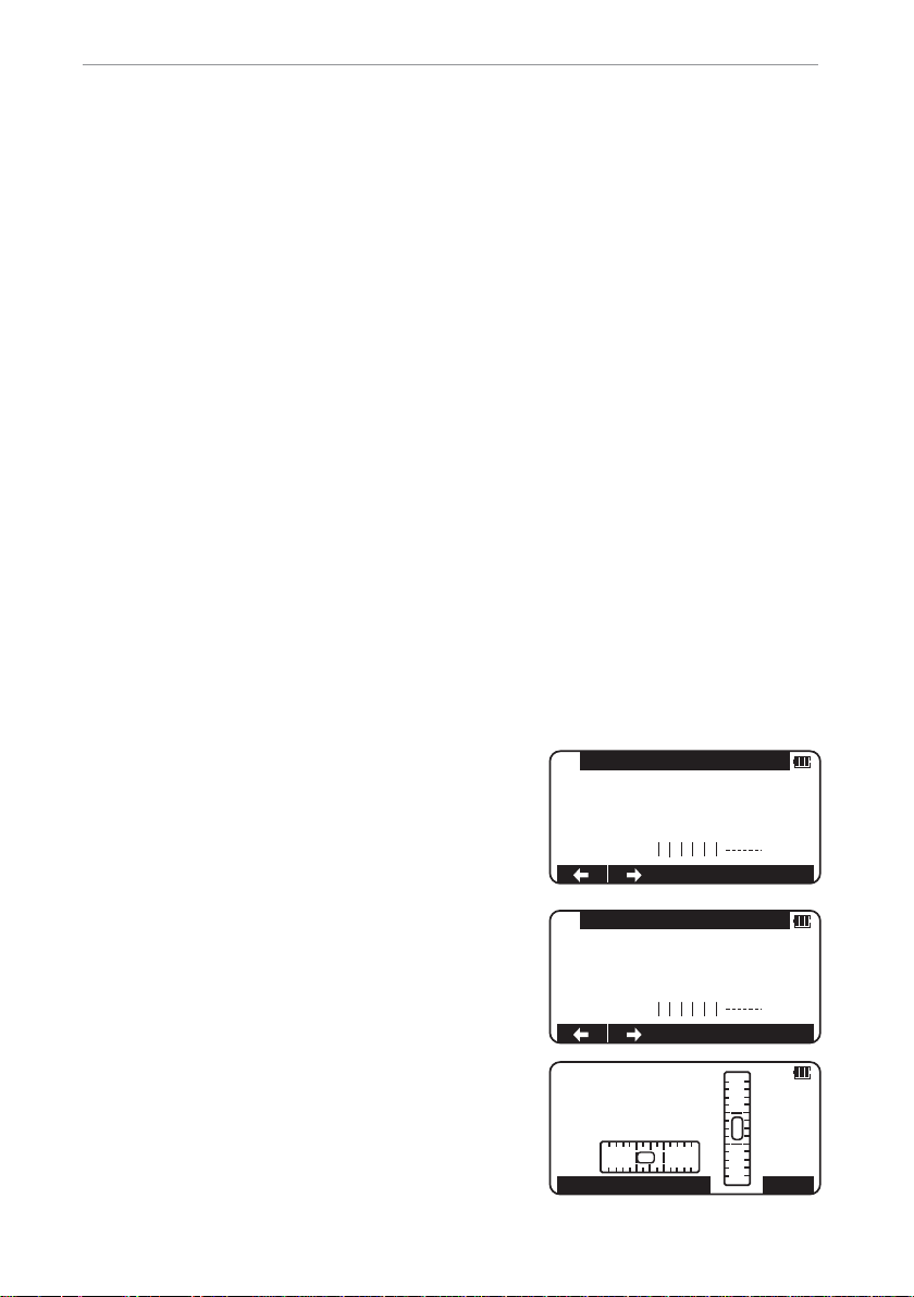
[Brightness adjustment of laser]
Sometimes the state of the surface of the ground mark or a surrounding environmental
dose not allow observing the laser spot easily.Please adjust the brightness of the laser if
necessary.
If the Laser key is pressed,the brightness adjustment
screen of the laser plummet device,is displayed.
The Laser plummet becomes dark by,
key and becomes bright by / key
The adjustment is completed with the ENT key and it
returns to electronic vial screen.
LD PLUM.POWER ADJ
DOWN0UP
10
5
ENT
ELECTRONICVIAL
T.COMP.
ON
30”/1DIV
SENS.
LD PLUM.POWER ADJ
DOWN
0
UP
10
5
LD POINT PLUM ADJ
ENT
24
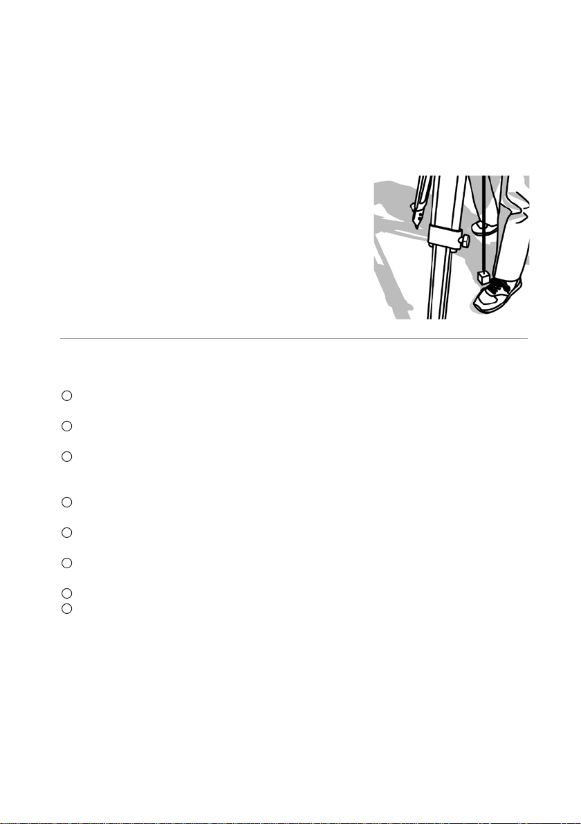
• The brightness adjustment step of the laser is 10 steps.
• The laser plummet spot can become difficult to see in bright sunlight which makes it
difficult to perform the occasional check.In this case,use your foot or the carrying case
to make a shadow over the laser position.
• The laser plummet is adjusted to be within ±0.8mm at the instrument height of 1.5m
at factory shipping.
• Please confirm the amount of the gap (direction of X and Y direction) with the laser
plummet beforehand compared with plumb bomb etc.
when working like accurately putting out a
perpendicular direction using the laser plummet function.
• Please do not look at the laser source of beam
directly.
3.3 Optical plummet (Option)
[Detachable type]
Look through the optical plummet eyepiece,and rotate the eyepiece knob until the
center mark can be seen clearly.
Rotate the focusing knob of the optical plummet and adjust the focus to the station
on the ground.
Rotate the levelling screws and aligh the center mark to the ground mark.
[Shift type]
Look through the optical plummet eyepiece,and rotate the eyepiece knob until the
center mark can be seen clearly.
Rotate the focusing knob of the optical plummet and adjust the focus on the ground
mark.
Loosen the centering clamp screw and push the upper plate by finger and stay the
center mark on the ground mark.
Tighten the centering clamp screw.
Loosen the horizontal clamp screw and rotate the instrument every 90°and confirm
the Circular vial is centered correctly. If the bubble is not centered,it can be properly
set using the leveling screws.
5
4
3
2
1
3
2
1
 Loading...