


TOTAL STATION
V-200SERIES
QUICK REFERENCE GUIDE
BASIC PROCEDURES POWER TOPO EXPRESS
PENTAX Industrial Instruments Co., Ltd.
2-5-2 Higashi-Oizumi
Nerima-Ku, Tokyo 178-8555, Japan Tel. +81 3 5905 1222
Fax +81 3 5905 1225
E-mail: international@piic.pentax.co.jp Website: www.pentax.co.jp/piic/survey
www.pentaxsurveying.com
Ahead of Vision

Quick Reference Guide Basic Procedures
for Total Station V-200 Series
V-227N
V-227
The description concerning the reflectorless function in this guide is applied to V-227N.
PENTAX Industrial Instruments Co.,Ltd.
|
3 |
|

CONTENTS |
|
|
General |
6 |
|
Instruction Manuals |
6 |
|
Precautions regarding safety |
6 |
|
Warning |
6 |
|
Usage Precautions |
7 |
|
|
|
|
1 |
Basic Operation |
8 |
1.1 |
Removing the Battery |
8 |
1.2 |
Attaching the Battery |
8 |
1.3 |
Turning the Power On and Off |
9 |
1.4 |
Display and keyboard |
9 |
1.4.1 |
Operation keys |
9 |
1.4.2 |
Function keys |
10 |
|
|
|
1.5 |
Angle Measurement |
12 |
1.5.1 |
Horizontal Angle |
12 |
1.5.2 |
Vertical Angle |
12 |
|
|
|
1.6 |
Distance Measurement |
13 |
1.6.1 |
Select your target |
13 |
1.6.2 |
Distance Measurement |
13 |
1.6.3 |
Changing Target constants |
13 |
1.6.4 |
Input Temperature and Atmospheric |
14 |
|
pressure |
|
1.6.5 |
Adjusting LCD contrast |
14 |
1.6.6 |
Adjusting Illumination brightness |
14 |
|
|
|
2 |
Changing Instrument Settings |
15 |
2.1 |
Help menu |
15 |
2.2 |
Instrument setting items |
15 |
|
|
|
3 |
Warning and Error Messages |
16 |
|
|
|
4 |
Specifications |
17 |
|
Notice to the user of this product |
19 |
|
4 |
|

|
PowerTopoExpress |
|
|
|
|
|
|
5 |
Starting Special Function |
24 |
|
6 |
Creating / Selecting a Job File |
24 |
|
7 |
Input a Known Point Coordinate |
25 |
|
8 |
Rectangular Coordinate Measurement |
26 |
|
8.1 |
Station Point Setup |
26 |
|
8.2 |
Orientation (Station Point H.Angle Setup) |
27 |
|
8.3 |
Measurement |
28 |
|
8.4 |
Offset Measurement |
29 |
|
8.5 |
Remote measurement |
30 |
|
9 |
Polar Coordinate Measurement |
31 |
|
9.1 |
Station Point Setup |
31 |
|
9.2 |
Orientation (Station Point H.Angle Setup) |
32 |
|
9.3 |
Measurement |
33 |
|
9.4 |
Offset measurement |
34 |
|
10 |
Free Stationing |
35 |
|
10.1 |
Known Point Setup |
35 |
|
10.2 |
Measuremen |
35 |
|
10.3 |
Calculation |
36 |
|
11 |
Stake Out |
36 |
|
11.1 |
Station Point Setup |
36 |
|
11.2 |
Orientation (Station Point H.Angle Setup) |
37 |
|
11.3 |
Stakeout Point Setup |
37 |
|
11.4 |
Stakeout Measurement |
37 |
|
12 |
Stake Out (Point to Line) |
39 |
|
12.1 |
Station Point Setup |
39 |
|
12.2 |
Orientation (Station Point H.Angle Setup) |
39 |
|
12.3 |
Point A Setup |
40 |
|
12.4 |
Point B Setup |
40 |
|
12.5 |
Point To Line Measurement |
41 |
|
13 |
INVERS |
42 |
|
14 |
Area Calculation |
42 |
|
15 |
REM |
43 |
|
16 |
RDM (Remote Distance Measurement) |
44 |
|
|
|
Preference List |
45 |
|
|
5 |
|
|
|
|
|
Instruction Manuals
Quick Reference Guide is intended to provide a quick reference in the field. For ease of use in the field, the following Quick Reference Guide booklets are provided in the carrying case.
1. Quick Reference Guide (Basic procedure)
(Power Topo Express,Operating procedure)
The complete instruction manuals are contained on the CD that is attached to each V-200.
This guide uses the symbol “ xN”as an expression of repeating times of key operation. For example. “ x2” means that [ESC] key is pressed two times.
The symbol “+”expresses that multiple keys are pressed simultaneously.
Before using this product,be sure that you have thoroughly read and understood the instruction manual that is included in the attached CD-ROM to ensure proper operation.
PWARNING
Solar Observation
Never view the sun directly using the telescope as this may result in loss of sight.
Laser Safety |
|
V-200 is a class-II (2) Laser product. Avoid direct eye exposure. Do not stare into laser beam.
Electro-Magnetic Compatibility (EMC)
This instrument complies with the protection requirement for residential and commercial areas. If this instrument is used close to industrial areas or transmitters, the equipment can be influenced by electromagnetic fields.
|
6 |
|

Risk of Explosion
Do not use this product in a location where there is coal dust,or near flammable material as there is a risk of explosion.
PUSAGE PRECAUTIONS
Target Constant
Confirm the Target Constant of the instrument before measurement.
Reflectorless
The reflectorless measurement range may vary depending on the target and surrounding brightness.
In case the reflectorless measurement results in low accuracy, perform the distance measurement by Prism. (V-227N)
Battery & Charger
Use the battery charger that is suitable to the battery you are using. If water should happen to splash on the instrument or the battery, wipe it off immediately and allow it to dry in a dry location.
|
7 |
|
1. Basic Operation
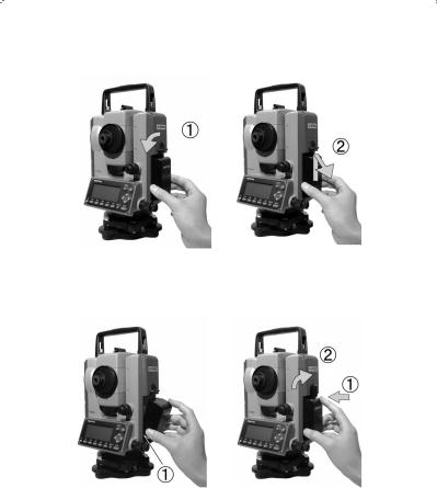
1.1 Removing the Battery
(1)Rotate the knob above the battery pack counter-clockwise.
(2)Lift up the battery pack and remove it from the instrument.
1.2Attaching the Battery
(1)Place the channel on the bottom of the battery pack, onto the protrusion of the instrument and push the battery pack down into place.
(2)Turn the knob clockwise.
|
8 |
|

1.3 Turning the Power On and Off |
|
|
To set power on : |
To shut down: |
|
To turn the power supply off, press the I/O key for more than 1 second and then release it. Power turns OFF.
NOTE: The power is automatically turned off after 10 minutes of inactivity (Factory default setting).
1.4 Display and keyboard 1.4.1 Operation keys
[ESC] |
Returns to previous screen or cancels an operation. |
|
|
|
Turns the illumination of the LCD display and telescope reticle |
|
on and off. |
|
|
|
Moves the cursor to the direction,respectively. |
|
The up or down increases or decreases the value,respectively. |
|
|
[ENT] |
Accepts the selected (highlighted) choice or the displayed |
|
screen value. |
|
|
[HELP] |
Pressing this key causes a help menu to appear in MODE A |
|
or MODE B or causes a help message to appear. |
|
|
|
9 |
|

1.4.2 Function keys
MODE A
[MEAS] |
Pressing this key one time measures the distance in |
|
|
normal mode.Pressing this key twice measures the |
|
|
distance in coarse mode. |
|
|
|
|
[TARGET] |
Select the target type by following order. |
|
|
PRISM / REFRECTORLESS |
(V-227N models only) |
|
|
|
[0 SET] |
Resets the horizontal angle to 0° 0’ 0” by pressing twice. |
|
|
|
|
[DISP] |
Switches the display composition in the order |
|
|
“H.angle / H.dst. / V.dst.”, “H.angle / V.angle / S.dst.” |
|
|
and “H.angle / V.angle / H.dst. / S.dst. / V.dst.” |
|
|
|
|
[MODE] |
Switches the screen between MODE A and MODE B. |
|
|
|
|
|
10 |
|
MODE B
[S.FUNC] |
PowerTopoExpress Special Functions |
|
|
[ANG SET] |
Brings up the angle setting screen for setting angle-related |
|
parameters. |
|
(H.ANGLE / %GRADE, H.ANGLE INPUT and R/L REVERSE) |
|
|
[HOLD] |
Pressing this key twice retains (holds) the horizontal angle |
|
shown on the display. |
|
|
[CORR] |
Brings up the screen for changing the target constant,temperature, |
|
Pressure setting. |
|
|
[MODE] |
Switches the screen between MODE A and MODE B. |
|
|
|
11 |
|
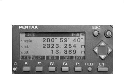
1.5 Angle Measurement
1.5.1 Horizontal Angle
|
Set the screen MODE A : |
MODE A screen |
|
|
Control keys for measuring horizontal angle: |
||
|
To set the angle to 0 |
: |
|
To hold the angle |
: |
|
|
|
|
|
|
|
To release HOLD |
: |
|
To input an angle |
: |
|
|
|
input value by using |
: |
|
|
To read clockwise angle : |
x2 |
|
|
|
|
|
1.5.2 Vertical angle
To display vertical angle :
To read the slope % :
|
12 |
|
1.6 Distance Measurement |
|
Set the screen MODE A : |
MODE A screen |
1.6.1 Select your target |
(V-227N models only) |
Select target type (measurement mode): |
|
(Prism) |
(Reflector-less) |
NOTE: The selected target is maintained until next time you change
1.6.2 Distance measurement
For a single shot measurement :
For tracking measurement |
: |
NOTE: The number of shots can be defined. The default is “one time”.The measuring modes activated by the above operations can be also changed.
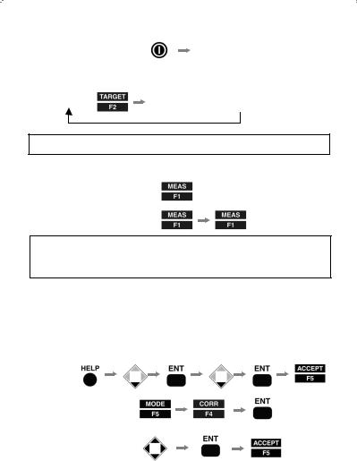
1.6.3 Changing Target constants
The default constants are: Prism : -30mm
Reflector-less : always 0mm (V-227N models only)
Before changing the constants,set Target Constant in the Initial Setting to “INPUT”mode:
|
|
x2 |
|
To change Prism constant:
input value by using:
|
13 |
|
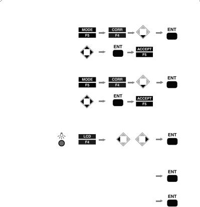
1.6.4 Input Temperature and Atmospheric pressure
To Input temperature : |
x2 |
|
|
input value by using:
To Input atmospheric pressure:
X3
input value by using:
1.6.5 Adjusting LCD contrast
+ |
or |
|
1.6.6 Adjusting Illumination brightness
for LCD
for Reticle
 +
+ 

 +
+ 

 or
or
 or
or


|
14 |
|
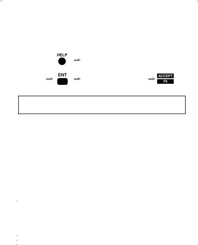
2. Changing Instrument settings
2.1 Help menu
While the screen is in MODE A or MODE B,
Select a desired item by  or
or
Change the setting 
NOTE: Some items have sub-menus where the selecting procedure by using direction keys is again repeated.
2.2 Instrument setting items
|
HELP menu list |
|
|
|
(Default) |
Other options |
|
|||
|
|
|
|
|
||||||
|
PRISM CONST |
|
|
(-30mm), |
0mm, INPUT |
|||||
|
ATM CORR |
|
|
(ATM INPUT), |
ppm INPUT, NIL |
|||||
|
SHOT COUNT |
SHOT CONT |
|
(1 time), |
3 times, 5 times, INPUT |
|||||
|
|
|
SHOT INPUT |
|
(01 times), input |
|||||
|
CRV/ REF CORR |
|
(0.14), |
0.2, NIL |
||||||
|
ATM CORR DISP |
|
(OFF), |
ON |
|
|
||||
|
MIN UNIT ANG. |
|
|
(FINE), |
|
COARSE |
||||
|
V. ANG. STYLE |
|
|
(Z. 0), |
H. 0, COMPASS |
|||||
|
QUAD BUZ |
|
|
(OFF), |
ON |
|
|
|||
|
AUTO OFF |
|
|
(10 MIN), |
20 MIN, 30 MIN, NIL |
|||||
|
EDM OFF |
|
(3 MIN), |
5 MIN, 10 MIN, NIL |
||||||
|
COMPENSATOR |
|
|
(ON), |
|
OFF |
|
|
||
|
ATM UNIT |
TEMP. UNIT |
|
(Centigrade), |
Fahrenheit |
|||||
|
|
|
PRESS UNIT |
|
(hPa), |
mmHg, inchHg |
||||
|
DIST. UNIT |
|
|
(m), |
ft, ft+ inch |
|||||
|
ANG. UNIT |
|
|
(DEG), |
|
DEC, GRD, MIL |
||||
|
SET UP COM. |
BAUD RATE |
(1200), |
|
2400, 4800, 9600 |
|
||||
|
|
|
DATA LENGTH |
(8), |
7 |
|
|
|
|
|
|
|
|
PARITY BITS |
|
(NIL), |
|
EVEN, ODD |
|||
|
|
|
STOP BITS |
(1), |
2 |
|
|
|
|
|
|
|
|
SIGNAL CONTROL |
|
(ON), |
|
OFF |
|
|
|
|
|
|
XON/ XOFF |
|
(ON), |
|
OFF |
|
|
|
|
|
|
THROUGH COMMAND |
(NIL), |
|
a, b, c, d, e, f |
||||
|
15 |
|
 Loading...