


|
Panasonic¡Panasonic¡P |
|
Panasonic¡Panasonic¡Pan |
|
¡Panasonic¡Panas |
|
¡Panasonic¡Panason |
|
¡Panasonic¡Panasonic¡ |
|
Panasonic¡Panasonic¡P |
|
Panasonic¡Panasonic¡Pan |
|
¡Panasonic¡Panas |
|
¡Panasonic¡Panason |
|
¡Panasonic¡Panasonic¡ |
|
Panasonic¡Panasonic¡P |
|
Panasonic¡Panasonic¡Pan |
|
¡Panasonic¡Panas |
|
¡Panasonic¡Panason |
|
¡Panasonic¡Panasonic¡ |
|
Panasonic¡Panasonic¡P |
|
Panasonic¡Panasonic¡Pan |
|
¡Panasonic¡Panas |
|
¡Panasonic¡Panason |
|
¡Panasonic¡Panasonic¡ |
|
Panasonic¡Panasonic¡P |
|
Panasonic¡Panasonic¡Pan |
|
¡Panasonic¡Panas |
|
¡Panasonic¡Panason |
|
¡Panasonic¡Panasonic¡ |
|
Panasonic¡Panasonic¡P |
|
Panasonic¡Panasonic¡Pan |
|
¡Panasonic¡Panas |
TX---28DK2 |
¡Panasonic¡Panason |
Panasonic¡Panasonic¡Pan |
|
|
¡Panasonic¡Panasonic¡ |
|
Panasonic¡Panasonic¡P |
Colour Television |
¡Panasonic¡Panas |
¡Panasonic¡Panason |
|
(U.K. Standard) |
¡Panasonic¡Panasonic¡ |
|
|
|
Panasonic¡Panasonic¡P |
|
Panasonic¡Panasonic¡Pan |
|
¡Panasonic¡Panas |
|
¡Panasonic¡Panason |
|
¡Panasonic¡Panasonic¡ |
|
Panasonic¡Panasonic¡P |
|
Panasonic¡Panasonic¡Pan |
|
¡Panasonic¡Panas |
|
¡Panasonic¡Panason |
|
¡Panasonic¡Panasonic¡ |
|
Panasonic¡Panasonic¡P |
|
Panasonic¡Panasonic¡Pan |
|
¡Panasonic¡Panas |
Operating Instructions |
¡Panasonic¡Panason |
|
¡Panasonic¡Panasonic¡ |
|
Panasonic¡Panasonic¡P |
|
Panasonic¡Panasonic¡Pan |
Dolby, Pro Logic and the are trademarks of Dolby Laboratories. |
|
Manufactured under license from Dolby Laboratories. |
¡Panasonic¡Panas |
|
¡Panasonic¡Panason |
TQB8E3317U---1 |
¡Panasonic¡Panasonic¡ |
|
Panasonic¡Panasonic¡P |

WELCOME
Dear Panasonic Customer,
Welcome to the Panasonic family of customers. We hope that you have many years of enjoyment from your new colour television. This is a very advanced television; however, the Quick Start Guide will allow you to use the TV as quickly as possible. You can then read the instructions completely and retain them for future reference.
CONTENTS
Warnings and Precautions . . . . . . . . . . . . . . . . . . . . . . . . 3
Accessories . . . . . . . . . . . . . . . . . . . . . . . . . . . . . . . . . . . . . 4
Inserting the Remote Control Batteries . . . . . . . . . . . . 4
Basic Controls . . . . . . . . . . . . . . . . . . . . . . . . . . . . . . . . . . |
5 |
Quick Start Guide . . . . . . . . . . . . . . . . . . . . . . . . . . . . . . . . 6
Using the On Screen Displays . . . . . . . . . . . . . . . . . . . 13
Aspect Control . . . . . . . . . . . . . . . . . . . . . . . . . . . . . . . . . 14
Picture Menu . . . . . . . . . . . . . . . . . . . . . . . . . . . . . . . . . . . 17
Sound Menu . . . . . . . . . . . . . . . . . . . . . . . . . . . . . . . . . . . |
18 |
Setup Menu . . . . . . . . . . . . . . . . . . . . . . . . . . . . . . . . . . . . |
19 |
Tuning Menu - overview . . . . . . . . . . . . . . . . . . . . . . . . . |
20 |
Tuning Menu - Programme edit . . . . . . . . . . . . . . . . . . 21 Tuning Menu - Auto setup . . . . . . . . . . . . . . . . . . . . . . . 25
Tuning Menu - Manual tuning . . . . . . . . . . . . . . . . . . . . 26 Tuning Menu - Shipping condition . . . . . . . . . . . . . . . 27
Tuning Menu - Owner I.D. . . . . . . . . . . . . . . . . . . . . . . . |
28 |
AV Select and Setup . . . . . . . . . . . . . . . . . . . . . . . . . . . . 29
Q-Link . . . . . . . . . . . . . . . . . . . . . . . . . . . . . . . . . . . . . . . . |
30 |
Dolby Pro Logic Surround Menu . . . . . . . . . . . . . . . . . |
32 |
Pro Logic mode . . . . . . . . . . . . . . . . . . . . . . . . . . . . . . . . |
33 |
Simulated mode . . . . . . . . . . . . . . . . . . . . . . . . . . . . . . . . 34
Speaker level setup . . . . . . . . . . . . . . . . . . . . . . . . . . . . . 34
VCR and Satellite Receiver Installation . . . . . . . . . . . 35
VCR/DVD Operation . . . . . . . . . . . . . . . . . . . . . . . . . . . . |
36 |
Teletext Operation . . . . . . . . . . . . . . . . . . . . . . . . . . . . . . |
37 |
Audio / Video (AV) Connections . . . . . . . . . . . . . . . . . . 39
Via the front AV3 4 pin S---Video, RCA Audio / Video
and Headphone sockets . . . . . . . . . . . . . . . . . . . . . . . . . . . 39
Scart and S--Video socket information . . . . . . . . . . . . . . . 39
Via the rear AV1 / AV2(S) 21 Pin Scart terminals . . . . . . . 40
Rear Dolby Surround Out RCA terminals ---
Audio out using external amplifiers and speakers . . . . . . 41
Troubleshooting . . . . . . . . . . . . . . . . . . . . . . . . . . . . . . . . 42 For your guidance . . . . . . . . . . . . . . . . . . . . . . . . . . . . . . 43 Specifications . . . . . . . . . . . . . . . . . . . . . . . . . . . . . . . . . . 43
2

WARNINGS AND PRECAUTIONS
D This TV set is designed to operate on 220 -- 240V, 50Hz A.C.
DTo prevent damage which might result in electric shock or fire, do not expose this TV set to rain or excessive moisture. This TV must not be exposed to dripping or splashing water and objects filled with liquid, such as vases, must not be placed on top of or above the TV.
DWARNING : HIGH VOLTAGE !!!
Do not remove the rear cover as live parts are accessible when it is removed. There are no user serviceable parts inside.
DAvoid exposing the TV set to direct sunlight and other sources of heat.
DThe On/Off switch on this model does not fully disconnect the TV from the mains supply. Remove the mains plug from the wall socket when the TV set is not used for a prolonged period of time.
DCABINET AND PICTURE TUBE CARE
Remove the mains plug from the wall socket. The cabinet and picture tube can be cleaned with a soft cloth moistened with mild detergent and water. Do not use solutions containing benzol or petroleum. TV sets can produce static electricity, care must be taken whenever touching the TV screen.
DAdequate ventilation is essential to prevent failure of electrical components, we recommend that a gap of at least 5cm is left all around this television receiver even when it is placed inside a cabinet or between shelves.
FOR YOUR SAFETY PLEASE READ THE FOLLOWING TEXT CAREFULLY
This appliance is supplied with a fitted three pin mains plug for your safety and convenience. A 5 amp fuse is fitted in this plug. If the fuse is replaced then the replacement fuse must be 5 amp rated and should be approved by ASTA or BSI to BS1362.
Check for the ASTA mark |
ASA |
or the BSI mark |
on the body of the fuse. |
|
If the fitted plug has a removable fuse cover you must ensure that it is refitted when the fuse is replaced. If you lose the fuse cover the plug must not be used until a replacement cover is obtained. Replacement fuse covers can be purchased through your local Panasonic dealer.
The plug fitted to this appliance incorporates a mains filter circuit. If this is removed or replaced with a non-filtered plug this television will no longer meet the European standards for Electromagnetic Compatibility (EMC). If the fitted plug is unsuitable for the socket outlet in your home an appropriate adapter should be used.
Nonetheless, if the fitted plug is replaced, the fuse should be taken out and the cut-off plug disposed of safely. There is danger of severe electrical shock if the cut off plug is inserted into any 13 amp. socket.
If a new plug is to be fitted please observe the wiring code as shown below. If in any doubt please consult a qualified electrician.
How to replace the fuse (for plug type shown in example 1) :
Lift out the removable fuse compartment with a screwdriver and replace the fuse, then refit securely into the mains plug (See example 1).
How to replace the fuse (for plug type shown in example 2) :
Lift open the fuse compartment, in the mains plug, with a screwdriver, and replace the fuse, then press the fuse cover down securely. (See example 2).
Example 1.
Example 2.
IMPORTANT :-- The wires in the mains lead of this appliance are coloured in accordance with the following code :-- BLUE : NEUTRAL BROWN : LIVE
As the colours of the wires in the mains lead of this appliance may not correspond to the markings identifying the terminals in your plug, proceed as follows :--
1.The BLUE wire must be connected to the terminal marked ‘N’ or coloured black.
2.The BROWN wire must be connected to the terminal marked ‘L’ or coloured red.
IMPORTANT NOTE : Under no circumstances should either of these wires be connected to the Earth terminal of the three pin plug, marked with the letter ‘E’ or the earth symbol. 
3
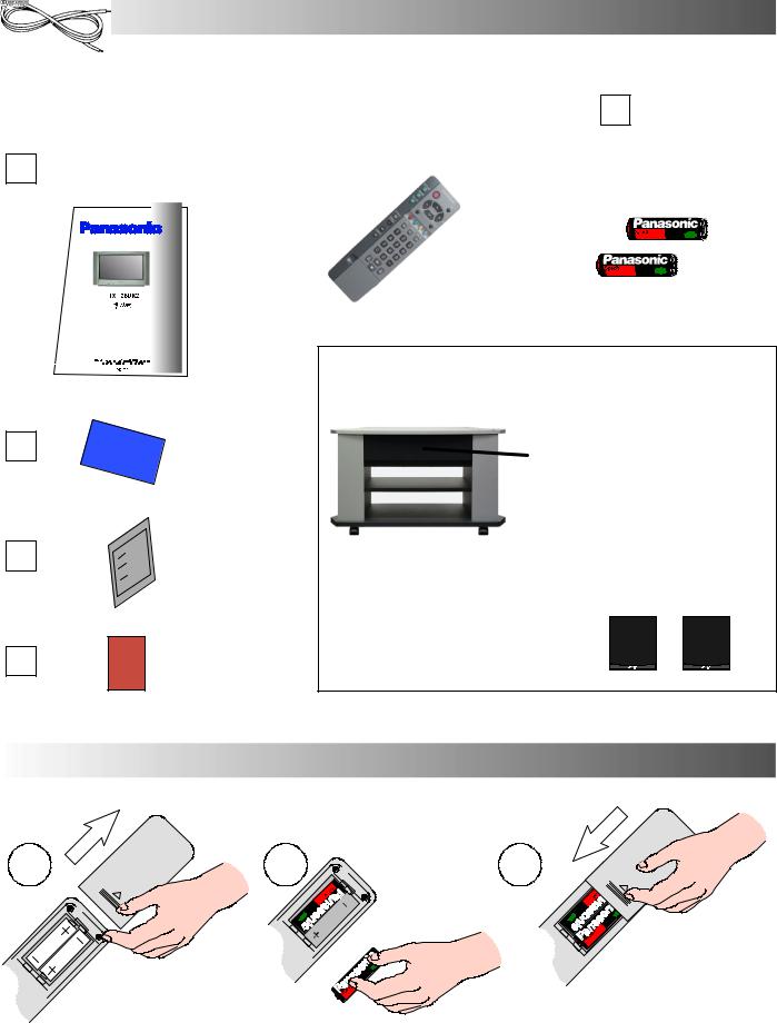
ACCESSORIES
Check that you have the accessories and items shown n
Operating Instruction book |
|
Remote Control Transmitter |
|
Batteries for the Remote Control |
|
|
|||
TQB8E3317U |
|
EUR511210 |
|
Transmitter. |
|
|
|
|
(2 x R6 (UM3) size) |
|
|
|
|
|
|
TS--900DP (Video cabinet / Speaker pack), comprising : |
|
|
|
|
|
|
|
|
|
|
|
|
|
|
|
|
|
|
|||
|
|
|
|
|
|
|
|
|
|
|
Video cabinet |
||
|
|
|
CRT Guarantee |
|
|
Centre speaker |
|
|
|
|
|
|
|
|
|
|
|
|
|
and 3D Subwoofer |
TV Guarantee
Speaker cables |
Rear surround speakers (x2) |
(12 metres each) |
Questionnaire
INSERTING THE REMOTE CONTROL BATTERIES
1 |
2 |
3 |
Slide off the battery cover |
Insert batteries -- note correct polarity |
Replace the cover |
|
(+ and --) |
|
Notes:
D Make sure that the batteries are fitted the correct way round.
D Do not mix old batteries with new batteries. Remove old, exhausted batteries immediately.
D Do not mix different battery types, i.e. Alkaline and Manganese. Do not use rechargeable (Ni--Cad) batteries.
4

BASIC CONTROLS : FRONT PANEL AND REMOTE CONTROL
Press here and open flap to expose TV controls, front AV3 and headphone terminals
Red light indicates Standby mode. Use Standby switch, ---, + or 0 ---9 buttons to switch TV On
MAINS Power On/Off switch
STR (Normalisation store)
Used to store tuning and other function settings
F (Function select) Displays the On Screen Display functions, use repeatedly to select from the available functions --- Volume, Contrast, Brightness, Colour, Sharpness, Tint (in NTSC mode), Bass, Treble, Balance and Tuning mode
Standby On/Off switch
Switches TV On or Off standby
Menu buttons Press to access the Picture, Sound and Setup menus (see page 13)
Status button Press to display programme position, programme name, channel number, time, NICAM mode and programme table
Teletext buttons (see page 37)
Direct TV Record button (see page 31)
Surround on/off
Aspect control button (see page 14)
Direct channel access During normal TV viewing or when in the Tuning, Programme edit or Manual tuning menus, press and then enter channel number using the numeric buttons
The N button will recall settings stored with STR
STR (Normalisation store)
RCA Audio/Video sockets (page 39)
S ---VHS socket (see page 39)
Headphone socket (see page 39)
TV/AV switch (see page 29)
Increases or decreases the programme position by one. When a function is already displayed, press to increase or decrease the selected function
Sound mute On/Off
Cursor buttons to make selections and adjustments
Switch between viewing TV or AV input (see page 29)
Coloured buttons used for
Programme Edit functions (see page 21) Teletext functions (see page 37)
AV selection (see page 29)
Programme / channel change
buttons (0- 9) and Teletext page buttons (see page 37)
When in Standby mode, switches TV on
Programme position for selection of two digit programmes (1099) using numeric buttons
VCR / DVD buttons (see page 36)
The Help button provides a demonstration of On Screen Display menus
5
QUICK START GUIDE
Connection and setting up options
1.If connecting the TV using an RF cable only, proceed to option 1.
2.If connecting the TV using Scart and RF cables, proceed to option 2.
3.If connecting the TV to a Q--Link (or Q--Link compatible) VCR, proceed to option 3 on page 7.
4.If connecting the TV to a Q--Link (or Q--Link compatible) VCR and a Satellite Receiver, proceed to option 4 on page 8.
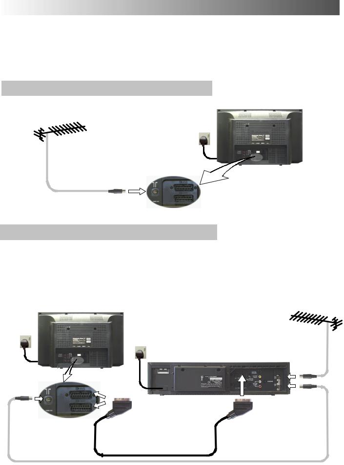
1.Connection of TV using an RF cable only
RF Connection
D Connect the RF cable into the TV Aerial socket ( 
 ).
).
Mains
Socket
Aerial Input socket
2.Connection of TV and VCR using Scart and RF cables
Scart Connections |
|
|
|
|
|
D |
The VCR can also be connected to the TV using a Scart cable if you are using a Scart equipped VCR. |
||||
D |
Use the TV’s AV1 Scart socket for a VCR. |
||||
D |
Use the TV’s AV2S Scart socket for an S---Video VCR. |
||||
RF Connection |
|
|
|
|
|
D |
Connect the RF cable to the Aerial In socket of the VCR and an RF cable from the VCR Aerial Out socket to the |
||||
|
TV Aerial socket ( |
|
|
|
). |
|
|
|
|||
TV
Mains
Socket
Mains
Socket
|
VCR |
Aerial |
|
Input |
|
|
|
|
|
|
socket |
Aerial |
|
|
Input |
AV1 and AV2 |
|
socket |
Scart sockets |
Aerial |
|
AV1 |
|
|
Output |
|
|
Scart socket |
socket |
Notes :
Additional equipment and cables are not supplied.
Further details of Audio/ Video connections can be found on pages 39 and 40.
6
QUICK START GUIDE
What is Q-Link ?
Q--Link allows direct communication between the TV and a Q--Link (or Q--Link compatible) VCR, this will enable features such as downloading of tuning information from the TV to the VCR.
When using a “NEXTVIEWLINK” VCR the main features possible are the following :
D |
Preset Download |
|
-- Downloading of tuning information from the TV to the VCR. |
D |
Direct TV Record |
|
-- For immediate recording of the current program (What You See Is What You Record). |
When using a “Q--Link” VCR the main features possible are the following : |
|||
D |
Preset Download |
|
-- Downloading of tuning information from the TV to the VCR. |
D |
Direct TV Record |
|
-- For immediate recording of the current program (What You See Is What You Record). |
D |
TV/VCR Auto Power On |
-- When the VCR plays a tape the TV will automatically switch On and select the AV2 input. |
|
D |
VCR Auto Power Standby |
-- When the TV is switched into Standby, the VCR will also switch into Standby. |
|
D |
VCR Image view On |
-- If the TV is in Standby mode and the VCR sends a menu to be displayed on the TV screen |
|
|
|
|
(e.g. Main menu), the TV will automatically switch On and the menu will be displayed. |
This TV will also communicate with other VCR’s that bear the following logos : |
|||
D |
“DATA LOGIC” |
(a trademark of Metz Corporation). |
|
D |
“Easy Link” |
(a trademark of Philips Corporation). |
|
D |
“Megalogic” |
(a trademark of Grundig Corporation). |
|
D |
“SMARTLINK” |
(a trademark of Sony Corporation). |
|
These VCR’s may support some or all of the above functions. Refer to the VCR operating instruction book. Further information on Q--Link can be found on page 30.
In order for Q-Link to function correctly, the Scart cables must be connected in a certain way, dependent on whether the TV is being connected to a VCR (option 3, below) or to a VCR and Satellite Receiver (option 4, overleaf).
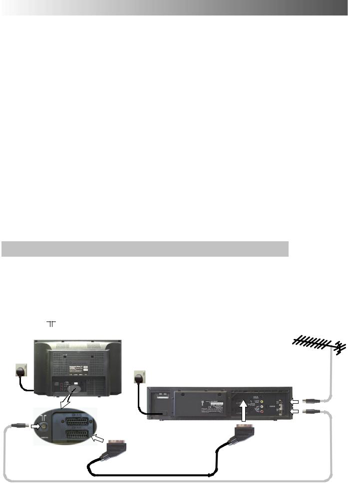
3.Q-Link connection of TV and VCR using Scart and RF cables
Scart Connection
D The VCR must be connected to the AV2 Scart socket of this TV using a ’fully wired’ Scart cable.
Note :
If using a “Q--Link” VCR then the AV1 Scart of the VCR must be connected to the AV2 socket of the TV. If your VCR is not a “Q--Link” VCR, please consult your VCR operating instruction book.
RF Connection
D Connect the RF cable to the Aerial In socket of the VCR and an RF cable from the VCR Aerial Out socket to the TV Aerial socket ( ).
TV |
|
|
|
Mains |
|
|
|
Socket |
|
Mains |
|
|
|
Socket |
|
|
|
VCR |
Aerial |
|
|
|
Input |
|
|
|
socket |
Aerial |
|
|
|
Input |
|
|
|
socket |
|
|
Aerial |
|
|
AV1 |
|
|
AV2 Scart |
Output |
|
|
Scart socket |
socket |
|
|
socket |
||
|
|
|
Notes :
Additional equipment and cables are not supplied.
Further details of Audio/ Video connections can be found on pages 39 and 40.
Further information for VCR and Satellite Receiver installation with this TV can be found on page 35.
7
QUICK START GUIDE
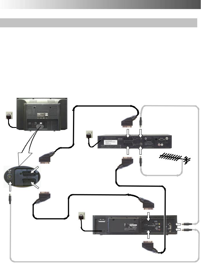
4. Q-Link connection of TV, VCR and Satellite Receiver using Scart and RF cables
For Q-Link to function correctly the TV, VCR and Satellite Receiver must be connected as shown in the diagram below.
Scart Connections
’Fully wired’ Scart cables should be used for all of the Scart connections.
D The AV2 Scart of the VCR must be connected to the VCR socket of the Satellite Receiver.
D The TV Scart socket of the Satellite Receiver must be connected to the AV1 Scart socket of the TV.
Note :
If using a “Q--Link” VCR then the AV1 Scart of the VCR must be connected to the AV2 socket of the TV. If your VCR is not a “Q--Link” VCR, please consult your VCR operating instruction book.
RF Connections
D Connect an RF cable to the Aerial In socket of the Satellite Receiver.
D Connect an RF cable from the RF Out socket of the Satellite Receiver to the RF In socket of the VCR.
D |
Connect an RF cable from the RF Out socket of the VCR to the TV Aerial In socket ( |
|
|
|
). |
|
|
|
TV
Mains
Socket
Mains |
|
Aerial |
|
Socket |
|
||
TV Scart |
Output |
||
|
|||
|
socket |
socket |
SATELLITE
RECEIVER
VCR Scart |
Aerial |
socket |
Input |
|
socket |
AV1 Scart
socket
AV2 Scart socket
Aerial
Input socket
Mains |
|
AV1 |
|
Socket |
VCR |
||
Scart socket |
|||
|
AV2
Scart socket
Notes :
Additional equipment and cables are not supplied.
Further details of Audio/ Video connections can be found on pages 39 and 40.
Further information for VCR and Satellite Receiver installation with this TV can be found on page 35.
Aerial Input socket
Aerial
Output
socket
8

QUICK START GUIDE
Connect the speakers
The TV must be switched Off.
1.Twist the wire ends before inserting.
2.Insert into terminals.
Ensure that bare speaker wires are not touching.
Press lever
Insert wire
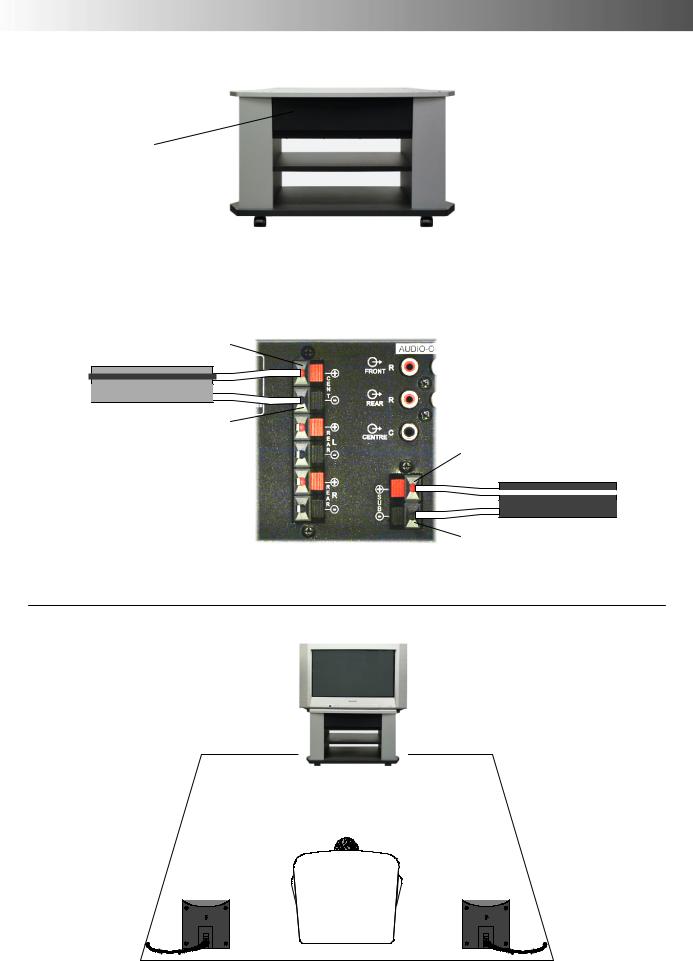
Rear Surround Speakers
Wall mounting point
Speaker stand mounting bracket, slide off to expose the speaker terminals. (Speaker stands are not supplied)
Rear of TV
Rear Left +
Rear Left --
Rear Right +
Rear Right --
The REAR speakers can be connected in one of two ways A or B :
A |
With both speakers connected in the same way |
B |
|
then the sound will be ‘true’ to the original |
|||
|
sound signal. |
|
|
Speaker |
|
Rear of TV |
Speaker |
Red (+) |
|
Red (+) |
|
|
Red (+) |
||
|
Grey / Black |
|
|
|
|
|
|
|
Grey |
Black (-) |
|
Black (-) |
|
Black (-) |
|
|
|
||
Speaker
Red (+)
Black (-)
With the wiring to one speaker ‘crossed over’ then an additional, artificial ambience effect will be created.
Rear of TV
Grey / Black |
Red (+) |
|
|
Grey |
Black (-) |
|
|
|
Rear of TV |
Grey / Black |
Red (+) |
|
Grey
Black (-)
9
QUICK START GUIDE
Centre speaker and 3D Subwoofer
Centre speaker and 3D Subwoofer
Centre Speaker
Centre +
Grey / Black
Grey
Centre --
Centre (Grey cable)
Connect Grey / Black to Red (+)
Connect Grey to Black (--)
Position the speakers
Left Rear
Surround Speaker
3D Subwoofer
Rear of TV
3D Subwoofer Speaker (Black cable)
Connect Black / White to Red (+) Connect Black to Black (--)
3D Subwoofer +
Black / White
Black
3D Subwoofer ---
Right Rear
Surround Speaker
10
QUICK START GUIDE
1 |
Ensure that the VCR is in Standby mode. |
2 |
Programmes will appear immediately if your dealer |
|
has programmed the TV for you. |
||
|
|
|
|
|
Switch ON your Satellite Receiver; to ensure |
|
If the TV has not been programmed for you then Auto |
|
reliable tuning select either SKY ONE or SKY |
|
setup will begin. TV stations will be located, sorted into |
|
NEWS (for analogue satellite receiver). Select any |
|
order and stored ready for use. *2 |
|
channel for digital satellite receiver. *1 |
|
|
|
Plug the TV into mains socket and switch ON. |
|
CH44 |
|
|
|
Mains |
|
|
Socket |
AUTO SETUP IN PROGRESS |
|
|
||
|
SEARCHING : PLEASE WAIT |
|
|
Stored |
CH44 BBC1 |
|
21 |
68 |
|
TV / AV : |
To exit |
3 |
Owner ID |
|
As an added feature, this TV has the option of adding a security code (Owner ID) and personal details into its memory, |
||
|
||
|
so that in the unfortunate event of theft it will help the Police to trace the owner. |
Enter required 4 digit Owner ID
PIN NUMBER.
(using 0 to 9 on the remote control).
4 Enter NAME, HOUSE NUMBER and POSTCODE.
If a 4 digit PIN NUMBER was entered above, you will be taken automatically to the NAME line.
If not, move to the NAME line.
Change character.
Select character position.
Repeat above until NAME, HOUSE NUMBER and POSTCODE are entered.
STR
Press STR to store the details. |
|
|
Press STR again, when you are asked |
STR |
|
“Are you sure ?” |
||
|
You now have the opportunity to enter your details and help the police crack crime see instruction book
|
|
|
|
|
|
|
|
|
|
|
|
|
|
Change |
||
|
|
|
|
|
|
|
|
|
|
|
|
|
|
|
character |
|
|
|
|
|
|
|
|
|
|
|
|
|
|
|
|
||
|
|
|
|
|
|
|
|
|
|
|
|
|
|
|
||
|
|
|
|
|
|
|
|
|
|
|
|
|
|
Select |
||
|
|
|
|
|
|
|
|
|
|
|
|
|
|
|||
|
|
|
|
|
|
|
|
|
|
|
|
|
|
|
character |
|
|
|
|
|
|
|
|
|
|
|
|
|
|
|
|
||
|
|
|
|
|
|
|
|
|
|
TV/AV |
|
Exit |
||||
|
’STR’ Button -- Store Owner ID |
|||||||||||||||
Owner ID |
|
|
|
|
|
|
|
|
|
|
|
|
|
|
||
|
|
|
|
|
|
|
|
|
|
|
|
|
|
|
|
|
PIN NUMBER : K |
K |
K |
K |
|
|
|
|
|
|
|
|
|
||||
NAME : K K K K K |
K |
K |
K |
K |
K |
K |
K |
K K |
||||||||
HOUSE NO |
: K |
K |
K |
K |
K |
K |
K |
K |
K |
K |
K |
|||||
POSTCODE |
: K |
K |
K |
K |
K |
K |
K |
K |
K |
K |
K |
|||||
|
|
|
|
|
|
|
|
|
|
|
|
|
|
|
|
|
0123456789 |
|
|
|
|
|
|
|
|
|
|
|
|
|
|
|
|
|
|
|
|
|
||||||||||||
|
|
You now have the opportunity |
|
|||||||||||||
|
|
to enter your details and |
|
|||||||||||||
|
|
help the police crack crime |
|
|||||||||||||
|
|
see instruction book |
|
|
|
|||||||||||
|
|
|
|
|
|
|
|
|
|
|
|
|
|
Change |
|
|
|
|
|
|
|
|
|
|
|
|
|
|
|
|
|
character |
|
|
|
|
|
|
|
|
|
|
|
|
|
|
|
Select |
|
|
|
|
|
|
|
|
|
|
|
|
|
|
|
|
|
||
|
|
|
|
|
|
|
|
|
|
|
|
|
|
|
character |
|
|
|
|
|
|
|
|
|
|
|
|
|
|
|
|
|
|
|
|
|
|
|
|
|
|
|
|
TV/AV |
|
Exit |
|
|||
|
’STR’ Button -- Store Owner ID |
|
||||||||||||||
Owner ID |
|
|
|
|
|
|
|
|
|
|
|
|
|
|
||
|
|
|
|
|
|
|
|
|
|
|
|
|
|
|
|
|
PIN NUMBER : 1 2 3 4 |
|
|
|
|
|
|
|
|
|
|
|
|||||
NAME : K K K K K |
K |
K |
K |
K |
K |
K |
K |
K K |
||||||||
HOUSE NO |
: K |
K |
K |
K |
K |
K |
K |
K |
K |
K |
K |
|||||
POSTCODE |
: K |
K |
K |
K |
K |
K |
K |
K |
K |
K |
K |
|||||
|
|
|
|
|
|
|
|
|
|
|
|
|||||
ABCDEFGHIJKLMNOPQRST |
|
|
|
|
|
|
|
|
|
|
|
|||||
UVWXYZ+--. 0123456789 |
|
|
|
|
|
|
|
|
|
|
|
|||||
|
|
|
|
|
|
|
|
|
|
|
|
|
|
|
|
|
For further information on Owner I.D., see page 28.
A space is provided on page 28 to write down the PIN NUMBER for future reference.
11
QUICK START GUIDE
5 |
TV to VCR Download |
|
|
|
|
|
|
||
|
If a “Q--Link”, “NEXTVIEWLINK” or compatible VCR |
|
|
|
|
has been connected to the AV2 socket before |
|
|
|
|
starting Step 1, programme information will be |
|
|
|
|
downloaded to the VCR. |
|
|
|
|
Downloaded tuning information will match the |
|
|
|
|
television’s. |
|
|
|
|
Not all VCRs support this download of |
|
|
|
|
programme information, some may require to be |
|
TV > VCR DOWNLOAD IN PROGRESS |
|
|
started manually. |
|
||
|
|
PLEASE WAIT |
||
|
Refer to the VCR operating instruction book. |
|
||
|
|
|
|
PROGRAMME : 48 |
|
|
|
|
REMOTE CONTROL UNAVAILABLE |
|
If a VCR other than those described above has |
|
|
|
|
|
|
|
|
|
|
BBC1 |
|
|
|
been connected, then there will be no download |
|
|
|
|
|
|
|
|
|
operation. |
|
|
|
Notes :
If the VCR has not accepted download data from the TV, you may need to select the Download option from the VCR’s menu system. Refer to the VCR operating instruction book.
If Q--Link is not operating correctly, check the following :
D The Scart cable is connected to the TV’s AV2 Scart socket.
D The Scart cable is connected to the VCR’s compatible (Q--Link, NEXTVIEWLINK or similar technology) Scart socket. D The Scart cable is a “fully wired” type.
For further information on Q--Link and connecting equipment, see pages 30, 39 and 40. |
|
|
|
|
||||||||||
*1. |
If, after Auto Setup is complete, the programme position of the digital satellite receiver is not to your preference, you can |
|||||||||||||
|
re---arrange the programme position. Refer to the Programme edit menu --- see page 21 for details. |
|
|
|||||||||||
*2. |
The sorting order depends upon the TV signal, the broadcasting system, and reception conditions. If either BBC1, BBC2 or |
|||||||||||||
|
ITV are not located, then their respective pre---allocated programme positions (1 to 3) will remain unused. |
|||||||||||||
|
|
|
|
|
|
|
|
|
|
|
|
|
|
|
|
Programme |
All stations |
|
No Channel 5 |
|
No Channel 5 |
|
No Channel 4 |
|
No S4C |
|
No Channel 4 |
|
No Channel 4 / S4C / |
|
Position |
available |
|
|
/ S4C |
|
/ Channel 5 |
|
|
/ S4C |
|
Channel 5 |
||
|
|
|
|
|
|
|
|
|
||||||
|
|
BBC1 |
|
BBC1 |
|
BBC1 |
|
BBC1 |
|
BBC1 |
|
BBC1 |
|
BBC1 |
|
1 |
|
|
|
|
|
|
|||||||
|
|
|
|
|
|
|
|
|
|
|
|
|
|
|
|
2 |
BBC2 |
|
BBC2 |
|
BBC2 |
|
BBC2 |
|
BBC2 |
|
BBC2 |
|
BBC2 |
|
|
|
|
|
|
|
|
|
|
|
|
|
|
|
|
3 |
ITV |
|
ITV |
|
ITV |
|
ITV |
|
ITV |
|
ITV |
|
ITV |
|
|
|
|
|
|
|
|
|
|
|
|
|
|
|
|
4 |
Channel 4 |
|
Channel 4 |
|
Channel 4 |
|
S4C |
|
Channel 4 |
|
Channel 5 |
|
Satellite |
|
|
|
|
|
|
|
|
|
|
|
|
|
|
|
|
5 |
S4C |
|
S4C |
|
Satellite |
|
Satellite |
|
Channel 5 |
|
Satellite |
|
~ |
|
|
|
|
|
|
|
|
|
|
|
|
|
|
|
|
6 |
Channel 5 |
|
Satellite |
|
~ |
|
~ |
|
Satellite |
|
~ |
|
~ |
|
|
|
|
|
|
|
|
|
|
|
|
|
|
|
|
7 |
Satellite |
|
~ |
|
~ |
|
~ |
|
~ |
|
~ |
|
~ |
|
|
|
|
|
|
|
|
|
|
|
|
|
|
|
|
Note : |
|
|
|
|
|
|
|
|
|
|
|
|
|
|
~ The next available channel will appear, if no other stations are available then the Programme position will remain unused. |
|||||||||||||
|
|
|
|
|
|
|
|
|
|
|
|
|
|
|
12
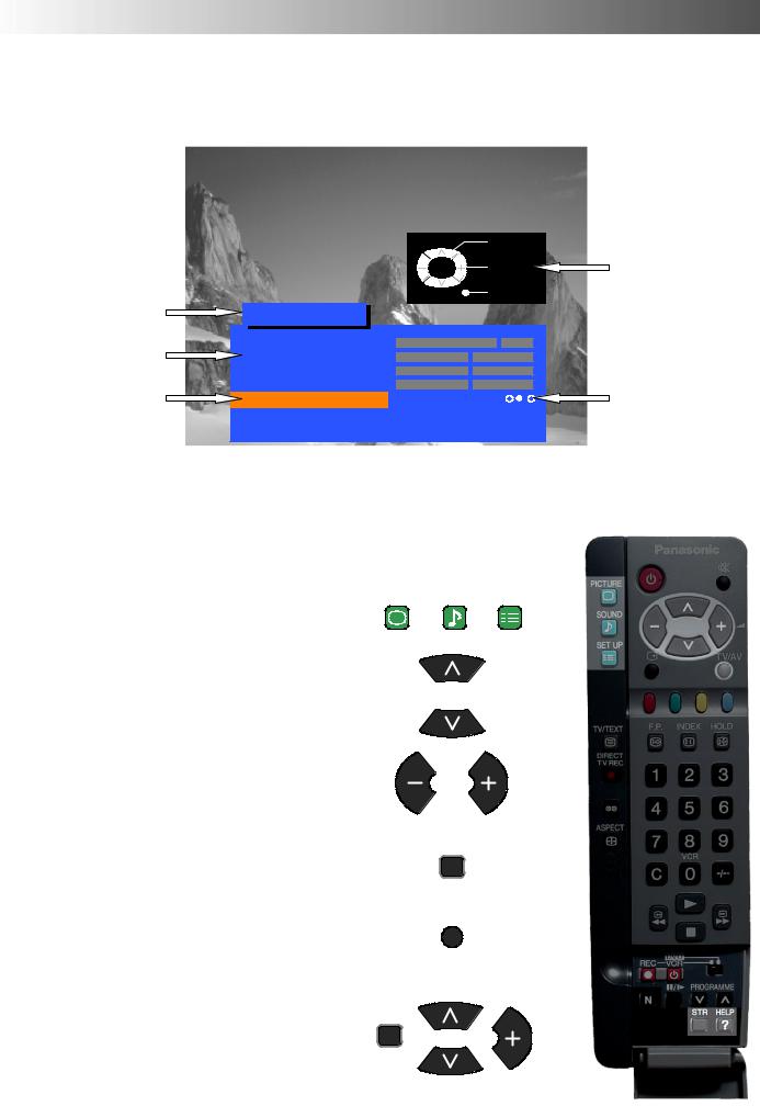
USING THE ON SCREEN DISPLAYS
This TV has a comprehensive system of On Screen Display menus to access adjustments and options
|
|
|
Select |
|
|
|
Change |
|
|
TV/AV |
Exit |
Menu Title |
Picture menu |
|
|
Sub-menus |
Contrast |
|
|
Brightness |
|
|
|
|
Colour |
|
|
Selection bar |
Sharpness |
|
|
Colour balance |
Normal |
|
|
|
P--NR |
Off |
|
|
AI |
On |
|
Instructions
Indicator for options
Some selections, for example, Contrast, Brightness, Colour and Sharpness will allow you to increase or decrease their level.
Some selections, for example, Off timer, allow a change of setting to be made. Some selections, for example Tuning menu, will lead to a further menu.
The PICTURE, SOUND and SET UP buttons are used to open the main menus and also to return to the previous menu.
The up and down cursor buttons are used to move the cursor up and down the menus.
The left and right cursor buttons are used to access menus, adjust levels or to select from a range of options.
The STR button is used to store settings after adjustments have been made or options have been set.
The TV/AV button is used to exit the menu system and return to the normal viewing screen.
The HELP button will run a demonstration of the menus available. Press the HELP button and select one of the options.
If the HELP button is pressed whilst a menu is displayed, the ’Instructions’ box will be hidden from view. Press the HELP button again to show the ’Instructions’ box.
PICTURE SOUND SET UP
STR
TV/AV
HELP
?
13
ASPECT CONTROLS
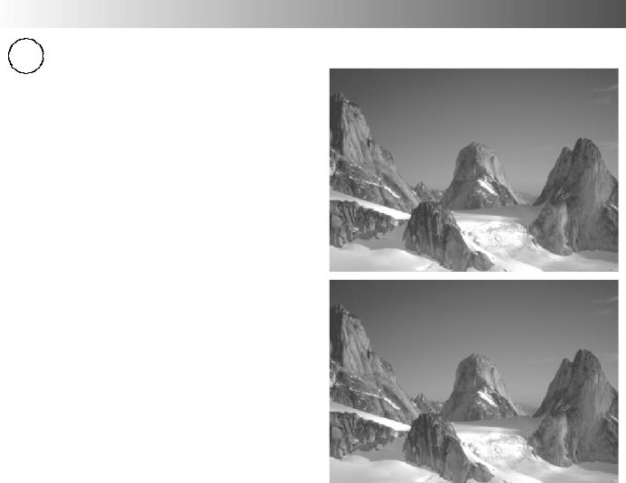
The widescreen TV will allow you to enjoy viewing the picture at its maximum size, including widescreen ‘cinema format’ pictures.
Note: Just mode is not available when viewing an RGB source.
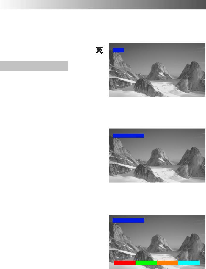
Press the ASPECT button to move through the ASPECT six aspect options: Panasonic Auto, 4:3, Zoom, 
16:9 (Full), 14:9 and Just.
Panasonic Auto
Panasonic Auto determines the best aspect ratio to use to display the picture you are viewing. It does this using a four step process to determine if the picture being viewed is a widescreen picture.
If Panasonic Auto detects a widescreen signal it switches into the appropriate 16:9 or 14:9 widescreen mode. If Panasonic Auto does not detect a widescreen signal then the picture is displayed in Just or 4:3 mode.
WIDE
’WIDE’ appears in the top left of the screen, Panasonic Auto switches to the appropriate 16:9 or 14:9 widescreen ratio.
The text shown on the screen indicates how Panasonic Auto determined which ratio to use:
’WIDE’ appears in the top left of the screen if a widescreeen identification signal (WSS) is found or a signal found through a Scart socket. Panasonic Auto switches to the appropriate 16:9 or 14:9 widescreen ratio
’Panasonic Auto’ appears in the top left of the screen if black stripes above and below the picture are detected. Panasonic Auto chooses the best ratio and expands the picture to fill the screen. This process can take several minutes, depending how dark the picture is.
’Panasonic Auto’ appears in the top left of the screen and red and green keys at the bottom if no indication of a widescreen signal is found, the picture is displayed in Just or 4:3 mode. If the picture has a standard 4:3 aspect ratio then you may prefer to view it at its original size, the red and green keys that appear allow you to choose between viewing at standard 4:3 size or expanded in Just mode.
Equally, you may prefer to select one of the other modes available to view the picture.
Notes:
DIf, in Panasonic Auto mode, you experience problems with the screen display size when playing back widescreen format recordings from your VCR then it is possible that the tracking control of your VCR requires adjustment (your VCR instruction book will contain adjustment details).
DThe widescreen aspect ratios of different films and programmes can vary. If these are wider than a standard 16:9 aspect picture then a black band may be visible at the top and bottom of the screen.
Panasonic Auto
’Panasonic Auto’ appears in the top left of the screen,
The best ratio is chosen and the picture expanded to fill the screen.
Panasonic Auto
4:3 Just
’Panasonic Auto’ appears in the top left of the screen, The picture is displayed in Just or 4:3 mode,
red and green keys appear, allowing switching between Just and 4:3 modes.
14
 Loading...