


SPECIFICATION
(Information in brackets { } refers to model TX-25LK1P)
Power Source: |
220-240V a.c., 50Hz |
Power Consumption: |
97W {105W} |
Stand-by Power |
|
Consumption: |
0,9W |
Aerial Impedance: |
75Ω unbalanced, Coaxial Type |
Receiving System: |
PAL B/G, PAL D/K ,PAL-60 |
|
SECAM B/G, SECAM D/K |
|
M.NTSC (AV) |
|
NTSC (AV only) |
Receiving Channels: |
|
VHF E2-E12 |
VHF H1-H2 (ITALY) |
VHF A-H (ITALY) |
VHF R1-R2 |
VHF R3-R5 |
VHF R6-R12 |
UHF E21-E69 |
CATV (S01-S05) |
CATV S1-S10 (M1-M10) |
CATV S11-S20 (U1-U10) |
CATV S21-S41 (HYPERBAND) |
|
Intermediate Frequency: |
|
Video/Audio |
|
Video |
38,9MHz |
Audio |
32,4MHz, 32,66MHz (A2 |
|
CZECH) |
|
33,05MHz (NICAM) |
|
33,4MHz, 33,16MHz (A2) |
|
33,05MHz (NICAM B/G) |
Colour |
34,47MHz |
Terminals: |
34,5MHz, 34,65MHz |
|
|
AV1 IN |
Video(21 pin) 1V p-p 75Ω |
|
Audio(21 pin) 500mV rms 10kΩ |
|
RGB (21 pin) 0,7V p-p 75Ω |
ORDER No. 00-SM-016
Colour Television
TX-28LK1P
TX-25LK1P
Z8 Chassis
AV1 OUT |
Video (21 pin) 1V p-p 75Ω |
|||
|
Audio (21 pin) 500mV rms 1kΩ |
|||
RCA IN |
Video |
1V p-p 75Ω |
||
RCA IN |
Audio |
500mV rms 10kΩ |
||
High Voltage: |
28kV ± 1kV |
|
||
Picture Tube: |
A66ECF50X04 |
66cm |
||
|
{A59EEQ15X97 |
59cm} |
||
Audio Output: |
2 x 10W (M.P.O.) |
|
||
|
2 x 5W |
(R.M.S.) |
|
|
Headphones: |
8Ω |
Impedance |
|
|
8Ω |
Impedance |
|
||
Accessories |
3,5mm |
|
|
|
|
|
|
|
|
supplied : |
Remote Control |
|
||
|
2 x R6 (UM3) Batteries |
|||
Dimensions: |
|
|
|
|
Height: |
571mm |
{522mm} |
||
Width: |
778mm |
{718mm} |
||
Depth: |
478mm |
{464mm} |
||
Net weight: |
31,5kg |
{26,75kg} |
||
Specifications are subject to change without notice. Weights and dimensions shown are approximate.
NOTE: This Service Manual should be used in conjunction with the Z8 Technical guide.

CONTENTS |
|
SAFETY PRECAUTIONS.......................................................................................................................................................... |
2 |
SERVICE HINTS ....................................................................................................................................................................... |
3 |
ADJUSTMENT PROCEDURE AND FACTORY SETTINGS ..................................................................................................... |
4 |
WAVEFORM PATTERN TABLE ............................................................................................................................................... |
5 |
ALIGNMENT SETTINGS........................................................................................................................................................... |
6 |
BLOCK DIAGRAMS .................................................................................................................................................................. |
7 |
PARTS LOCATION ................................................................................................................................................................. |
10 |
REPLACEMENT PARTS LIST ................................................................................................................................................ |
11 |
SCHEMATIC DIAGRAMS ....................................................................................................................................................... |
17 |
CONDUCTOR VIEWS............................................................................................................................................................. |
20 |
SAFETY PRECAUTIONS
GENERAL GUIDE LINES
1.It is advisable to insert an isolation transformer in the a.c. supply before servicing a hot chassis.
2.When servicing, observe the original lead dress in the high voltage circuits. If a short circuit is found, replace all parts that have been overheated or damaged by the short circuit.
3.After servicing, see that all the protective devices such as insulation barriers, insulation papers, shields and isolation R-C combinations are correctly installed.
4.When the receiver is not being used for a long period of time, unplug the power cord from the a.c. outlet.
5.Potentials as high as 29kV are present when this receiver is in operation. Operation of the receiver without the rear cover involves the danger of a shock hazard from the receiver power supply. Servicing should not be attempted by anyone who is not familiar with the precautions necessary when working on high voltage equipment. Always discharge the anode of the tube.
6.After servicing make the following leakage current checks to prevent the customer from being exposed to shock hazard.
LEAKAGE CURRENT COLD CHECK
1.Unplug the a.c. cord and connect a jumper between the two prongs of the plug.
2.Turn on the receiver’s power switch.
3.Measure the resistance value with an ohmmeter, between the jumpered a.c. plug and each exposed metallic cabinet part on the receiver, such as screw heads, aerials, connectors, control shafts etc. When the exposed metallic part has a return path to the chassis, the reading should be between 4M ohm and 20M ohm. When the exposed metal does not have a return path to the chassis, the reading must be infinite.
LEAKAGE CURRENT HOT CHECK
1.Plug the a.c. cord directly into the a.c. outlet. Do not use an isolation transformer for this check.
2.Connect a 2kΩ 10W resistor in series with an exposed metallic part on the receiver and an earth, such as a water pipe.
3.Use an a.c. voltmeter with high impedance to measure the potential across the resistor.
4.Check each exposed metallic part and check the voltage at each point.
5.Reverse the a.c. plug at the outlet and repeat each of the above measurements.
HOT CHECK CIRCUIT
a.c. VOLTMETER
|
|
|
|
|
|
|
|
|
|
WATER PIPE |
|
|
|
|
|
|
|
|
|
|
|
||
|
|
|
2kΩ 10 Watts |
|
|||||||
|
|
|
|
|
|
|
|
|
|
|
(EARTH) |
|
|
|
|
|
|
|
|
|
|
|
|
TO INSTRUMENT'S EXPOSED |
|
|
|
||||||||
METALLIC PARTS |
Fig. 1. |
|
|
|
|||||||
|
|
|
|
|
|
|
|
|
|||
6.The potential at any point should not exceed 1,4Vrms. In case a measurement is outside the limits specified, there is a possibility of a shock hazard, and the receiver should be repaired and rechecked before it is returned to the customer.
X-RADIATION WARNING
1.The potential sources of X-Radiation in TV sets are the high voltage section and the picture tube.
2.When using a picture tube test jig for service, ensure that the jig is capable of handling 29kV without causing X-Radiation.
NOTE: It is important to use an accurate periodically calibrated high voltage meter.
1.Set the brightness to minimum.
2.Measure the high voltage. The meter should indicate.
28 kV ± 1kV.
If the meter indication is out of tolerance, immediate service and correction is required to prevent the possibility of premature component failure.
3.To prevent any X-Radiation possibility, it is essential to use the specified tube.
2
SERVICE HINTS
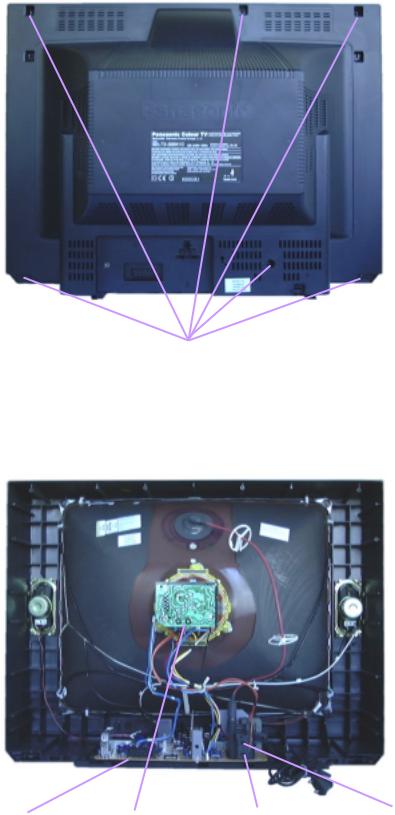
How to remove the rear cover
1.Remove the 6 screws as shown in Fig.2.
Screws
Fig.2.
LOCATION OF CONTROLS
E - Board |
Y - Board |
Screen |
Focus |
|
|
Fig.3. |
|
3

ADJUSTMENT PROCEDURE
|
Item/Preparation |
|
|
|
Adjustments |
|
|
|
|||
+B SET-UP |
|
Confirm the following voltages. |
|
|
|
|
|||||
1. Receive a Greyscale signal. |
TPE1 |
3,3 |
± |
0,3V |
TPE13 |
-13 |
± |
1V |
|||
2. |
Set the controls: |
|
|||||||||
|
Brightness |
Minimum |
TPE2 |
195 |
± |
10V |
TPE14 |
27,5 |
± |
1,5V |
|
|
TPE3 |
13,5 |
± |
1V |
TPE15 |
28 |
± |
1,5V |
|||
|
Contrast |
Minimum |
TPE4 |
10 |
± |
1V |
TPE16 |
11,5 |
± |
1V |
|
|
TPE8 |
5 |
± |
0,3V |
TPE17 |
8 |
± |
1V |
|||
|
Volume |
Minimum |
TPE11 |
147 |
± |
10V |
TPE18 |
5 |
± |
0,3V |
|
|
|
|
|
|
|
|
|
|
|||
|
|
|
|
|
|
|
|
|
|||
Cut-Off / Ug2 Adjustment |
Set Contrast on maximum, set Brightness on centre, switch |
||||||||||
1. |
Receive a Greyscale signal. |
||||||||||
on AV mode. |
|
|
|
|
|
|
|||||
2. |
Degauss the tube externally. |
|
|
|
|
|
|
||||
Enter Service mode. Set Sub-Brightness to 31. Select |
|
||||||||||
3. |
Set the TV into Service Mode 1. |
|
|||||||||
Ug2.Press "+" and adjust screen Vr till sharp vertical line is |
|||||||||||
4. |
Select Ug2 Test. |
||||||||||
visible and LED switches off. Then reduce screen Vr till LED |
|||||||||||
|
|
|
|||||||||
|
|
|
is just switched on (pin6 of connector E1 must be connected |
||||||||
|
|
|
to GND). |
|
|
|
|
|
|
|
|
|
|
|
|
|
|
|
|
|
|
|
|
Note: To set up ”white balance” first set up “Cut off” register to 8. Then set up “high-light” with the help of “drive” registers. Finish setting-up of “Low-light” with the help of ”Cut-off” register. Carry out setting-up of ”white balance” in available TV systems (PAL, SECAM).
FACTORY SETTINGS
To return customer settings to factory settings and clear owner ID of all information input by the customer, enter Self-Check mode. Press the down (-/v) button on the customer controls at the front of the TV set, at the same time pressing the STATUS button  on the remote control. To exit Self Check, switch off the TV set at the power button.
NOTE: Self Check should only be used when refurbishing the TV set and not during normal repair work.
OPTION 1 |
EC |
OPTION 2 |
00 |
|
|
Service Aids
To aid in the service of our current chassis there are a number of Service Aids which have been made available.
•LUCI interface kit (Linked Utility Computer Interface) Part number: TZS6EZ002
This contains interface and cables for connecting TV service connector and a PC as well as diagnostic software. As new models are introduced upgrade software will become available.
•VICI (Visual Interactive Computer Information)
These C.D.'s contain multimedia documentation providing quick access to service information. Part No. TZS7EZ006, TZS7EZ005, TZS8EZ001& TZS9EZ001
1.Service Manuals
2.Instruction Books
3.Technical Information
•TASMIN (Technically Advanced System for Multimedia Interactive Notes)
As well as providing a first step towards more interactive training this product also achieves quick access to Technical Information.
4
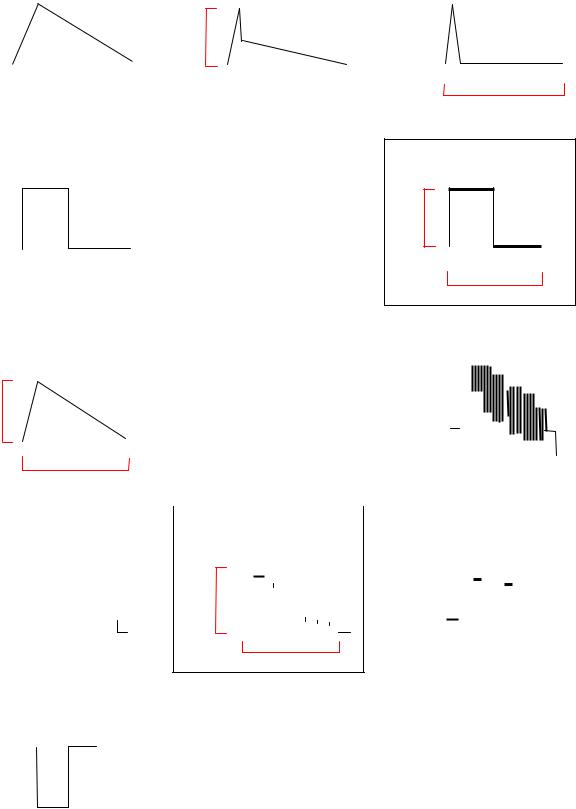
WAVEFORM PATTERN TABLE
|
|
|
|
|
IC 601 |
|
|
|
|
|
|
|
|
|
|
|
|
|
|
|
|
|
|
|
|
|
|
|
|
|
|
|
|
|
|
|
|
|
|||||||
|
|
|
|
|
|
|
|
|
|
|
|
|
|
|
|
|
|
VERT - OUT |
|
||||||||||||||||||||||||||
|
|
|
|
|
Pin 21 |
|
|
|
|
|
|
|
|
|
|
|
|
|
|
||||||||||||||||||||||||||
|
|
|
|
|
|
|
|
|
|
|
|
|
|
|
|
|
|
|
|
|
|
|
|
|
|
|
|
|
|
|
|
|
|
|
|
|
|
||||||||
|
|
|
|
|
|
|
|
|
|
|
|
|
|
|
|
|
|
|
|
|
|
|
|
|
|
|
|
|
|
|
|
|
|
|
|
|
|
|
|
|
|
|
|
|
|
|
|
|
|
|
|
|
|
|
|
|
|
|
|
|
|
|
|
|
|
|
|
|
|
|
|
|
|
|
|
|
|
|
|
|
|
|
|
|
|
|
|
|
|
|
|
|
|
|
|
|
|
|
|
|
|
|
|
|
|
|
|
|
|
|
|
|
|
|
|
|
|
|
|
|
|
|
|
|
|
|
|
|
|
|
|
|
|
|
|
|
|
|
|
|
|
|
|
|
|
|
|
|
|
|
|
|
|
|
|
|
|
|
|
|
|
|
|
|
|
|
|
|
|
|
|
|
|
|
|
|
|
|
|
|
|
|
|
|
|
|
|
|
1V |
|
|
|
|
|
|
|
|
|
|
|
|
|
|
|
|
|
|
|
|
|
|
|
|
|
|
|
|
|
|
|
|
|
|
|
|
|
|
|
|
|
|
|
|
|
|
|
|
|
|
|
|
|
|
|
|
|
|
|
|
|
|
|
|
|
|
|
|
|
|
|
|
|
|
|
|
|
|
|
|
|
|
|
|
||
|
|
|
|
|
|
|
|
|
|
|
|
|
|
|
|
|
|
|
|
|
|
|
|
|
|
|
|
|
|
|
|
|
|
|
|
|
|
|
|
|
|
|
|
|
|
|
|
|
|
|
|
|
|
|
|
|
|
|
|
|
|
|
|
|
|
|
|
|
|
|
|
|
|
|
|
|
|
|
|
|
|
|
|
|
|
|
|
|
|
|
|
|
|
|
|
|
|
|
|
|
|
|
|
|
|
|
|
|
|
|
|
|
|
|
20ms |
|
|
|
|
|
|
|
|
|
|
|
|
|
|
||||||||
|
|
|
|
|
|
|
|
|
|
|
|
|
|
|
|
|
|
|
|||||||||||||||||||||||||||
|
|
|
|
|
|
|
|
|
|
|
|
|
|
|
|
|
|
|
|
|
|
|
|
|
|
|
|
|
|
|
|
|
|
|
|
|
|
|
|
|
|
|
|
|
|
|
|
|
|
|
|
|
|
|
|
|
|
|
|
|
|
|
|
|
|
|
|
|
|
|
|
|
|
|
|
|
|
|
|
|
|
|
|
|
|
|
|
|
|
|
|
|
|
|
|
|
|
|
|
|
|
|
|
|
|
|
|
|
|
|
|
|
|
|
|
|
|
|
|
|
|
|
|
|
|
|
|
|
|
|
|
|
|
|
|
|
|
|
|
|
|
|
|
|
|
|
|
|
|
|
|
|
|
|
|
|
|
|
|
|
|
|
|
|
|
|
|
|
|
|
|
|
|
|
|
|
|
|
|
|
|||
|
|
|
|
|
IC 601 |
|
|
|
|
|
|
|
|
|
|
|
|
|
|
|
H - OUT |
|
|
|
|||||||||||||||||||||
|
|
|
|
|
Pin 33 |
|
|
|
|
|
|
|
|
|
|
|
|
|
|
|
|
|
|
|
|
|
|
|
|
|
|
|
|
|
|
|
|
|
|||||||
|
|
|
|
|
|
|
|
|
|
|
|
|
|
|
|
|
|
|
|
|
|
|
|
|
|
|
|
|
|
|
|
|
|
|
|
|
|
|
|
|
|
|
|
|
|
|
|
|
|
|
|
|
|
|
|
|
|
|
|
|
|
|
|
|
|
|
|
|
|
|
|
|
|
|
|
|
|
|
|
|
|
|
|
|
|
|
|
|
|
|
|
|
|
|
|
|
|
|
|
|
|
|
|
|
|
|
|
|
|
|
|
|
|
|
|
|
|
|
|
|
|
|
|
|
|
|
|
|
|
|
|
|
|
|
|
||
|
|
|
|
|
|
3V |
|
|
|
|
|
|
|
|
|
|
|
|
|
|
|
|
|
|
|
|
|
|
|
|
|
|
|
|
|
|
|
|
|
|
|
|
|
|
|
|
|
|
|
|
|
|
|
|
|
|
|
|
|
|
|
|
|
|
|
|
|
|
|
|
|
|
|
|
|
|
|
|
|
|
|
|
|
|
|
|
|
||||
|
|
|
|
|
|
|
|
|
|
|
|
|
|
|
|
|
|
|
|
|
|
|
|
|
|
|
|
|
|
|
|
|
|
|
|
|
|
|
|
|
|
|
|
|
|
|
|
|
|
|
|
|
|
|
|
|
|
|
|
|
|
|
|
|
|
|
|
|
|
|
|
|
|
|
|
|
|
|
|
|
|
|
|
|
|
|
|
|
|
|
|
|
|
|
|
|
|
|
|
|
|
|
|
|
|
|
|
|
|
|
|
|
|
|
|
64 s |
|
|
|
|
|
|
|
|
|
|
|
|
|||||||||
|
|
|
|
|
|
|
|
|
|
|
|
|
|
|
|
|
|
|
|
|
|
|
|
|
|
|
|
||||||||||||||||||
|
|
|
|
|
|
|
|
|
|
|
|
|
|
|
|
|
|
|
|
|
|
|
|
|
|
|
|
|
|
|
|
|
|
|
|
|
|
|
|
|
|
|
|
||
|
|
|
|
|
|
|
|
|
|
|
|
|
|
|
|
|
|
|
|
|
|
|
|
|
|
|
|
|
|
|
|
|
|
|
|
|
|
|
|
|
|
|
|
|
|
|
|
|
|
|
|
|
|
|
|
|
|
|
|
|
|
|
|
|
|
|
|
|
|
|
|
|
|
|
|
|
|
|
|
|
|
|
|
|
|
|
|
||||
|
|
|
|
|
IC 701 |
|
|
|
|
|
|
|
|
|
|
|
|
|
|
|
|
|
|
|
|
|
|
|
HFLB |
|
|||||||||||||||
|
|
|
|
|
Pin 8 |
|
|
|
|
|
|
|
|
|
|
|
|
|
|
|
|
|
|
|
|
|
|
|
|
|
|
|
|
|
|
|
|
|
|||||||
|
|
|
|
|
|
|
|
|
|
|
|
|
|
|
|
|
|
|
|
|
|
|
|
|
|
|
|
|
|
|
|
|
|
|
|
|
|||||||||
|
|
|
|
|
|
|
|
|
|
|
|
|
|
|
|
|
|
|
|
|
|
|
|
|
|
|
|
|
|
|
|
|
|
|
|
|
|
|
|
|
|
|
|||
|
|
|
|
|
|
2V |
|
|
|
|
|
|
|
|
|
|
|
|
|
|
|
|
|
|
|
|
|
|
|
|
|
|
|
|
|
|
|
|
|
|
|
||||
|
|
|
|
|
|
|
|
|
|
|
|
|
|
|
|
|
|
|
|
|
|
|
|
|
|
|
|
|
|
|
|
|
|
|
|
|
|
|
|
||||||
|
|
|
|
|
|
|
|
|
|
|
|
|
|
|
|
|
|
|
|
|
|
|
|
|
|
|
|
|
|
|
|
|
|
|
|
|
|
|
|
|
|
|
|
|
|
|
|
|
|
|
|
|
|
|
|
|
|
|
|
|
|
|
|
|
|
|
|
|
|
64 s |
|
|
|
|
|
|
|
|
|
||||||||||||
|
|
|
|
|
|
|
|
|
|
|
|
|
|
|
|
|
|
|
|
|
|
|
|
|
|
|
|
|
|
|
|
|
|
|
|
|
|
|
|
|
|
||||
|
|
|
|
|
|
|
|
|
|
|
|
|
|
|
|
|
|
|
|
|
|
|
|
|
|
|
|
|
|
|
|
|
|
|
|
|
|
|
|
|
|
|
|
|
|
|
|
|
|
|
|
|
|
|
|
|
|
|
|
|
|
|
|
|
|
|
|
|
|
|
|
|
|
|
|
|
|
|
|
|
|
|
|||||||||
|
|
|
|
|
IC 601 |
|
|
|
|
|
|
|
|
|
|
|
|
|
|
|
|
|
|
|
|
R - OUT |
|
||||||||||||||||||
|
|
|
|
|
Pin 51 |
|
|
|
|
|
|
|
|
|
|
|
|
|
|
|
|
|
|
|
|
|
|
|
|
|
|
|
|
|
|
|
|
|
|||||||
|
|
|
|
|
|
|
|
|
|
|
|
|
|
|
|
|
|
|
|
|
|
|
|
|
|
|
|
|
|
|
|
|
|
|
|
|
|
||||||||
|
|
|
|
|
|
|
|
|
|
|
|
|
|
|
|
|
|
|
|
|
|
|
|
|
|
|
|
|
|
|
|
|
|
|
|
|
|
|
|
|
|
||||
|
|
|
|
|
|
|
|
|
|
|
|
|
|
|
|
|
|
|
|
|
|
|
|
|
|
|
|
|
|
|
|
|
|
|
|
|
|
|
|
|
|
||||
|
|
|
|
|
|
2,7V |
|
|
|
|
|
|
|
|
|
|
|
|
|
|
|
|
|
|
|
|
|
|
|
|
|
|
|
|
|
|
|
|
|
|
|
|
|||
|
|
|
|
|
|
|
|
|
|
|
|
|
|
|
|
|
|
|
|
|
|
|
|
|
|
|
|
|
|
|
|
|
|
|
|
|
|
|
|
|
|
||||
|
|
|
|
|
|
|
|
|
|
|
|
|
|
|
|
|
|
|
|
|
|
|
|
|
|
|
|
|
|
|
|
|
|
|
|
|
|
||||||||
|
|
|
|
|
|
|
|
|
|
|
|
|
|
|
|
|
|
|
|
|
|
|
|
|
|
|
|
|
|
|
|
|
|
|
|
|
|
|
|
|
|
|
|
|
|
|
|
|
|
|
|
|
|
|
|
|
|
|
|
|
|
|
|
|
|
|
|
|
|
64 |
s |
|
|
|
|
|
|
|
|
|
|
|
|
||||||||
|
|
|
|
|
|
|
|
|
|
|
|
|
|
|
|
|
|
|
|
|
|
|
|
|
|
|
|
|
|||||||||||||||||
|
|
|
|
|
|
|
|
|
|
|
|
|
|
|
|
|
|
|
|
|
|
|
|
|
|||||||||||||||||||||
|
|
|
|
|
|
|
|
|
|
|
|
|
|
|
|
|
|
|
|
|
|
|
|
|
|
|
|
|
|
|
|
|
|
|
|
|
|
|
|
||||||
|
|
|
|
|
|
|
|
|
|
|
|
|
|
|
|
|
|
|
|
|
|
|
|
|
|
|
|
|
|
|
|
|
|
|
|
|
|
|
|
|
|
|
|
|
|
|
|
|
|
|
|
|
|
|
|
|
|
|
|
|
|
|
|
|
|
|
|
|
|
|
|
|
|
|
|
|
|
|
|
|
|
|
|
|
|
|
|
|
|
|
|
|
|
|
|
|
|
|
|
|
|
|
|
|
|
|
|
|
|
|
|
|
|
|
|
|
|
|
|
|
|
|
|
|
|
|
|
|
|
|
|
|
|
|
|
|
|
|
|
|
|
|
IC 601 |
|
|
|
|
|
|
|
|
|
|
|
|
|
|
|
|
|
|
|
|
|
|
|
SCL |
|
|||||||||||||||
|
|
|
|
|
Pin 2 |
|
|
|
|
|
|
|
|
|
|
|
|
|
|
|
|
|
|
|
|
|
|
|
|
|
|
|
|
|
|
|
|
|
|||||||
|
|
|
|
|
|
|
|
|
|
|
|
|
|
|
|
|
|
|
|
|
|
|
|
|
|
|
|
|
|
|
|
|
|
|
|
|
|
||||||||
|
|
|
|
|
|
|
|
|
|
|
|
|
|
|
|
|
|
|
|
|
|
|
|
|
|
|
|
|
|
|
|
|
|
|
|
|
|
|
|
|
|
|
|||
|
|
|
|
|
|
|
|
|
|
|
|
|
|
|
|
|
|
|
|
|
|
|
|
|
|
|
|
|
|
|
|
|
|
|
|
|
|
|
|
|
|
|
|||
|
|
|
|
|
|
|
|
|
|
|
|
|
|
|
|
|
|
|
|
|
|
|
|
|
|
|
|
|
|
|
|
|
|
|
|
|
|
|
|
|
|
|
|||
|
|
|
|
|
|
5V |
|
|
|
|
|
|
|
|
|
|
|
|
|
|
|
|
|
|
|
|
|
|
|
|
|
|
|
|
|
|
|
|
|
||||||
|
|
|
|
|
|
|
|
|
|
|
|
|
|
|
|
|
|
|
|
|
|
|
|
|
|
|
|
|
|
|
|
|
|
|
|
|
|
|
|
|
|
|
|
|
|
|
|
|
|
|
|
|
|
|
|
|
|
|
|
|
|
|
|
|
|
|
|
|
|
|
|
|
|
|
|
|
|
|
|
|
|
|
|
|
|
|
|
|
|
|
|
|
|
|
|
|
|
|
|
|
|
|
|
|
|
|
|
|
|
|
|
|
|
|
|
|
|
|
|
|
|
|
|
|
|
|
|
|
|
|
|
|
|
|
|
|
|
|
|
|
|
|
|
|
|
|
|
|
|
|
|
|
|
|
|
|
|
|
|
|
47 s |
|
|
|
|
|
|
|
|
|
|
|
|
|
|
|
|
|
|
||||
|
|
|
|
|
|
|
|
|
|
|
|
|
|
|
|
|
|
|
|
|
|
|
|
|
|
|
|
|
|
|
|
|
|
|
|
|
|
|
|
|
|||||
|
|
|
|
|
|
|
|
|
|
|
|
|
|
|
|
|
|
|
|
|
|
|
|
|
|
|
|
|
|
|
|
|
|
|
|
|
|
|
|
|
|
|
|
|
|
|
|
|
|
|
|
|
|
|
|
|
|
|
|
|
|
|
|
|
|
|
|
|
|
|
|
|
|
|
|
|
|
|
|
|
|
|
|
|
|
|
|
|
|
|
|
IC 451 |
|
|
|
|
|
|
|
|
|
|
|
|
VERT - DRIVE |
|
|||||
Pin 2 |
|
|
|
|
|
|
|
|
|
|
|
|
|
|
|
|
|
|
|
|
|
|
|
|
|
|
|
|
|
50V |
|
|
|
|
|
|
|
|
|
|
|
|
|
|
|
|
|
|
|
|
|
|
|
|
|
|
|
|
|
|
|
|
|
|
20ms |
|
|
|
|
|
|
|
|
|
|
|
|||
|
|
|
|
|
|
|
|
|
|
|
|
|
|
|
|
|
|
|
|
|
|
|
|
|
|
|
|
|
|
|
|
|
IC 701 |
|
|
|
|
|
|
|
|
|
|
|
|
|
|
|
|
|
|
|
|
|
|
|
|
|
|
|
|||||
|
|
|
|
|
|
|
|
|
|
|
|
|
|
|
EW - OUT |
|
|||||||||||||||||||
|
|
|
Pin 5 |
|
|
|
|
|
|
|
|
|
|
|
|
|
|
|
|
|
|
|
|
|
|
|
|
|
|||||||
|
|
|
|
|
|
|
|
|
|
|
|
|
|
||||||||||||||||||||||
|
|
|
|
|
|
|
|
|
|
|
|
|
|
|
|
|
|
|
|
|
|
|
|
|
|
|
|
|
|
|
|
|
|
|
|
|
|
|
|
|
|
|
|
|
|
|
|
|
|
|
|
|
|
|
|
|
|
|
|
|
|
|
|
|
|
|
|
|
|
|
|
|
|
|
20V |
|
|
|
|
|
|
|
|
|
|
|
|
|
|
|
|
|
|
|
|
|
|
|
|
|
|
|
|
|
|
|
|
|
|
|
|
|
|
|
|
|
|
|
|
|
|
|
|
|
|
|
|
|
|
|
|
|
|
||||||||||
|
|
|
|
|
|
|
|
|
|
|
|
|
|
|
|
|
|
|
|
|
|
|
|
|
|
|
|
|
|
|
|
|
|
|
|
|
|
|
|
|
|
|
|
|
|
|
|
|
|
|
|
|
|
|
|
|
|
|
|
|
|
|
|
|
|
|
|
|
|
|
|
|
|
|
|
|
|
|
|
|
|
|
|
|
|
|
|
|
|
|
|
|
|
|
|
|
|
|
|
|
|
|
|
|
|
|
|
|
|
|
|
|
|
|
|
|
|
|
|
|
|
|
|
|
64 |
s |
|
|
|
|
|
|
|
||||||||||
|
|
|
|
|
|
|
|
|
|
|
|
|
|
|
|
|
|
|
|
|
|
|
|
|
|
|
|
|
|
|
|
|
|
|
|
|
|
|
|
|
|
|
|
|
|
|
|
|
|
|
|
|
|
|
|
|
|
|
|
|
|
|
|
|
|
|
|
|
|
|
|
|
|
|
|
|
|
|
|
|
|
|
|
|
|
|
|
|
|
|
|
|
|
|
|
|
|
|
|||||||||
|
|
|
IC 601 |
|
|
|
|
|
|
|
|
|
|
|
|
|
FBI/SCO |
||||||||||||||||||
|
|
|
Pin 34 |
|
|
|
|
|
|
|
|
|
|
|
|
|
|
|
|
|
|
|
|
|
|
|
|
||||||||
|
|
|
|
|
|
|
|
|
|
|
|
|
|
|
|
||||||||||||||||||||
|
|
|
|
|
|
|
|
|
|
|
|
|
|
|
|
|
|
|
|
|
|
|
|
|
|
|
|
|
|
|
|
||||
|
|
|
|
|
|
|
|
|
|
|
|
|
|
|
|
|
|
|
|
|
|
|
|
|
|
|
|
|
|
|
|
||||
|
|
|
|
|
|
|
|
|
|
|
|
|
|
|
|
|
|
|
|
|
|
|
|
|
|
|
|
|
|
|
|||||
|
|
|
5,7V |
|
|
|
|
|
|
|
|
|
|
|
|
|
|
|
|
|
|
|
|
|
|
|
|
|
|
|
|
||||
|
|
|
|
|
|
|
|
|
|
|
|
|
|
|
|
|
|
|
|
|
|
|
|
|
|
|
|||||||||
|
|
|
|
|
|
|
|
|
|
|
|
|
|
|
|
|
|
|
|
|
|
|
|
|
|
|
|
||||||||
|
|
|
|
|
|
|
|
|
|
|
|
|
|
|
|
|
|
|
|
|
|
|
|
|
|
|
|
|
|
|
|
|
|
|
|
|
|
|
|
|
|
|
|
|
|
|
|
|
|
|
|
|
|
|
|
|
|
|
|
|
|
|
|||||||||
|
|
|
|
|
|
|
|
|
|
|
|
|
|
|
|
|
64 s |
|
|
|
|
|
|||||||||||||
|
|
|
|
|
|
|
|
|
|
|
|
|
|
|
|
|
|
|
|
|
|
|
|
|
|
|
|
|
|
|
|
|
|
|
|
|
|
|
|
|
|
|
|
|
|
|
|
|
|
|
|
|
|
|
|
|
|
|
|
|
|
|
|
|
|
|
|
|
|
|
|
|
|
|
|
|
|
|
|
|
|
|
|
|
|
|
|
|
|
|
|
||||||||||||||||
|
|
|
|
|
|
|
|
|
|
|
|
|
|
|
|
|
|
|
|||||||||||||||||
|
|
|
IC 601 |
|
|
|
|
|
|
|
|
|
|
G - OUT |
|||||||||||||||||||||
|
|
|
Pin 52 |
|
|
|
|
|
|
|
|
|
|
|
|
|
|
|
|
|
|
|
|
|
|
|
|||||||||
|
|
|
|
|
|
|
|
|
|
|
|
|
|
|
|
|
|||||||||||||||||||
|
|
|
|
|
|
|
|
|
|
|
|
|
|
|
|
|
|
|
|
|
|
|
|
|
|
||||||||||
|
|
|
|
|
|
|
|
|
|
|
|
|
|
|
|
|
|
|
|
|
|
|
|
||||||||||||
|
|
|
2,7V |
|
|
|
|
|
|
|
|
|
|
|
|
|
|
|
|
|
|
|
|
|
|||||||||||
|
|
|
|
|
|
|
|
|
|
|
|
|
|
|
|
|
|
|
|
|
|
|
|
|
|
|
|
|
|
|
|
|
|
||
|
|
|
|
|
|
|
|
|
|
|
|
|
|
|
|
|
|
|
|
|
|
|
|
|
|
|
|
|
|
|
|
|
|
|
|
|
|
|
|
|
|
|
|
|
|
|
|
|
|
|
|
|
|
|
|
|
|
|
|
|
|
|
|
|
|
|
|
|
|
|
|
|
|
|
|
|
|
|
|
|
|
|
|
|
|
|
|
|
|
|
|
|
|
|
|
|
|
|
|
|
|
|
|
|
|
|
|
|
|
|
|
|
|
|
|
|
|
|
|
|
|
|
|
|
|
|
|
|
|
|
|
|
|
|
|
|
|
|
|
|
|
|
|
64 s
|
|
|
|
|
|
|
|
|
|
|
|
|
IC 451 |
|
|
|
|
|
|||
|
|
|
|
VFLB |
|
|||||
|
|
Pin 3 |
|
|
|
|
|
|||
|
|
|
|
|
|
|||||
|
|
|
|
|
|
|
|
|
|
|
|
|
|
|
|
|
|
|
|
|
|
|
|
|
|
|
|
|
|
|
|
|
|
|
28,4V |
|
|
|
|
|
|
|
|
|
|
|
|
|
|
|
|
|
||
|
|
|
|
|
|
|
|
|
|
|
|
|
|
|
|
|
|
|
|
|
|
|
|
|
|
|
|
|
20ms |
|
|
|
|
|
|
|
|
|
|
|
|
|
|
|
|
|
|
|
|
|
|
|
|
|
Base Q501 |
|
H - PULSE |
|
|
|
|
|
|
1,4V
64 s
IC601 |
|
|
|
|
VIDEO OUT |
|
|||||||
Pin 38 |
|
|
|
|
|
|
|
|
|
|
|||
|
|
|
|
|
|
|
|
|
|
|
|
|
|
2,7 V |
|
|
|
|
|
|
|
|
|
|
|
|
|
|
|
|
|
|
|
|
|
|
|
|
|
|
|
|
|
|
|
|
|
|
|
|
|
|
|
|
|
|
|
|
64 s |
|
|
|
|
|
|||||
|
|
|
|
|
|
|
|
|
|
|
|||
|
|
|
|
|
|
|
|
|
|
|
|||
|
|
|
|
|
|
|
|
|
|
|
|
||
|
|
|
|
|
|
|
|
|
|
||||
|
|
|
|
|
|
|
|
|
|
||||
|
|
|
|
|
|
|
|
||||||
|
|
|
|
|
|
|
|
|
|
|
|
|
|
|
|
|
|
|
|
|
|
|
|
|
|
|
|
|
|
|
|
|
|
|
|
|
|
|
|
|
|
|
|
|
|
|
|
|
|
|
|
|
|
|
IC 601 |
|
|
|
|
|
|
|
|
|
|
B - OUT |
|
||||||||||
|
|
Pin 53 |
|
|
|
|
|
|
|
|
|
|
|
|
|
|
|
|
||||||
|
|
|
|
|
|
|
|
|
|
|
|
|
|
|
|
|||||||||
|
|
|
|
|
|
|
|
|
|
|
|
|
|
|
|
|
|
|
|
|
|
|
|
|
|
|
|
|
|
|
|
|
|
|
|
|
|
|
|
|
|
|
|
|
|
|
|
|
|
|
|
2,7V |
|
|
|
|
|
|
|
|
|
|
|
|
|
|
|
|
|
|
|
|
|
|
|
|
|
|
|
|
|
|
|
|
|
|
|
|
|
|
|
|
|
|
|
|
|
|
|
|
|
|
|
|
|
|
|
|
|
|
|
|
|
|
|
|
|
|
|
|
|
|
|
|
|
|
|
|
|
|
|
|
|
|
|
|
|
|
|
|
|
|
|||||||
|
|
|
|
|
|
|
|
|
|
|
|
|
|
|
|
|
|
|||||||
|
|
|
|
|
|
|
|
|
|
|
|
|
|
|
|
|
|
|||||||
|
|
|
|
|
|
|
|
|
|
|
|
|
|
|
|
|
|
|
|
|
|
|
|
|
|
|
|
|
|
|
|
|
|
|
|
|
|
|
|
|
|
|
|
|
|
|
|
|
|
|
|
|
|
|
|
|
|
|
|
|
|
|
|
|
|
|
|
|
|
|
|
|
|
|
|
|
|
|
|
|
|
|
|
|
|
|
|
|
64 s |
|
|
|
|
||||||
|
|
|
|
|
|
|
|
|
|
|
|
|
|
|
||||||||||
|
|
|
|
|
|
|
|
|
|
|
|
|
|
|
|
|
|
|
|
|
|
|
|
|
|
|
|
|
|
|
|
|
|
|
|
|
|
|
|
|
|
|
|
|
|
|
|
|
|
5
ALIGNMENT SETTINGS
To access Service Mode select program position 99 and set sharpness to minimum.
Press “MUTE” button on remote control and at the same time press the "V" button on the customer controls at the front of the TV, this will place the TV set into Service Mode.
Press / buttons to step up / down through the functions.
Press + / - buttons to alter the function values.
Press “STR” button on the customer controls at the front of the TV after each adjustment has been made to store the required values.
To exit Service Mode press “N” button.
|
Setting indication |
|
|
Alignment Function |
Note: All setting values are |
Settings / Special features |
|
|
approximate |
|
|
1. Cut off (Ug2) |
LED On/Off |
LED to be just On |
|
(pin6 of connector E1 to the GND) |
|||
|
|
||
|
|
|
|
2. Vertical slope |
V-SLO 32 |
Optimum setting |
|
|
|
|
|
3. Vertical shift |
V-POS 43 |
Optimum setting. |
|
|
|
|
|
4. Vert. Amplitude |
V-AMP 60 |
Optimum setting. |
|
|
|
|
|
5. Horizontal shift |
H-CTR 31 |
Optimum setting. |
|
|
|
|
|
6. Horizontal parallelogram |
H-PAR 034 |
Optimum setting. |
|
|
|
|
|
7. Horizontal bow |
H-BOW 031 |
Optimum setting. |
|
8. R - Cut |
R - CUT 08 |
Optimum setting. |
|
|
|
|
|
9. G - Cut |
G - CUT 08 |
Optimum setting. |
|
|
|
|
|
10. R - Drive |
R - DRV 31 |
Optimum setting. |
|
|
|
|
|
11. G - Drive |
G - DRV 31 |
Optimum setting. |
|
|
|
|
|
12. B - Drive |
B - DRV 31 |
Optimum setting. |
|
|
|
|
|
13. AGC |
AGC 20 |
Optimum setting. |
|
|
|
|
|
14. Sub Colour |
S - COL 15 |
Optimum setting. |
|
|
|
|
|
15. Sub Brightness |
S - BRI 31 |
Optimum setting. |
|
|
|
|
|
16. Horizontal Width |
EW – WD 34 |
Optimum setting. |
|
|
|
|
|
17. EW parabola |
EW – PR 32 |
Optimum setting. |
|
|
|
|
|
18. EW Upper corners |
EW – UC32 |
Optimum setting. |
|
|
|
|
|
19. EW Lower corners |
EW – LC 33 |
Optimum setting. |
|
|
|
|
|
20. EW Trapezoid |
EW – TP 36 |
Optimum setting. |
|
|
|
|
Input remote code "FA" followed by key 5 (14 hex) or press "Status button" on remote control (numerical keys 0-6 to change value, TV/AV button to store on remote control):
Option Byte - 1 |
Option Byte Table |
|
|||
|
|
|
|
|
|
Bit No. |
Value |
Functions |
|
|
|
|
|
|
|
|
|
0 |
0 |
French model |
0 |
NO |
|
1 |
YES |
||||
|
|
|
|||
1 |
0 |
Irish model |
0 |
NO |
|
1 |
YES |
||||
|
|
|
|||
2 |
1 |
NICAM enabled |
0 |
NO |
|
1 |
YES |
||||
|
|
|
|||
3 |
1 |
A2 stereo enabled |
0 |
NO |
|
1 |
YES |
||||
|
|
|
|||
4 |
0 |
Tuner manufacturer |
0 |
MACO |
|
1 |
ALPS |
||||
|
|
|
|||
5 |
1 |
CRT |
0 |
21" |
|
1 |
25",28" |
||||
|
|
|
|||
6 |
1 |
Q - link enabled |
0 |
NO |
|
1 |
YES |
||||
|
|
|
|||
7 |
1 |
TOP TEXT enabled |
0 |
YES |
|
1 |
NO |
||||
|
|
|
|||
|
|
|
|
6 |
|
Option Byte - 2 |
Option Byte Table |
||||
|
|
|
|
||
Bit No. |
Value |
Functions |
|
||
|
|
|
|
|
|
0 |
0 |
SOUND AI |
0 |
NO |
|
1 |
YES |
||||
|
|
|
|||
1 |
0 |
|
|
|
|
|
|
|
|
|
|
2 |
0 |
|
|
|
|
|
|
|
|
|
|
3 |
0 |
|
|
|
|
|
|
|
|
|
|
4 |
0 |
|
|
|
|
|
|
|
|
|
|
5 |
0 |
|
|
|
|
|
|
|
|
|
|
6 |
0 |
|
|
|
|
|
|
|
|
|
|

|
|
|
|
|
|
< |
< |
|
9 |
|
|
|
|
|
|
|
',$*5$0%/2&.'()/(&7,216833/<32:(5 |
|
|
|
( |
|
|
7 |
|
|
2 |
|
|
+ |
|
(
(
 Loading...