


TX-21JT2P

Colour Television
TX-21JT2P
TX-21JT2P/B
Z-M3L Chassis
SPECIFICATIONS
Power Source: 220-240V a.c., 50Hz
Power Consumption: 60W
Stand-by Power
Consumption: 1W
Aerial Impedance: 75Ω unbalanced, Coaxial Type
Receiving System: PAL-B/G, DK , PAL-525/60
SECAM B/G, D/K
M.NTSC
NTSC (AV only)
Receiving Channels:
VHF E2-E12 VHF H1-H2 (ITALY)
VHF A-H (ITALY) VHF R1-R2
VHF R3-R5 VHF R6-R12
UHF E21-E68 CATV (S01-S05)
CATV S1-S10 (M1-M10) CATV S11-S20 (U1-U10)
CATV S21-S41 (HYPERBAND)
Intermediate Frequency:
Video/Audio
Video 38.9MHz, 34MHz
Audio 32.9MHz, 33.16MHz, 33.4MHz
Colour 34.47MHz (PAL)
34.5MHz, 34.65MHz (SECAM)
Video/Audio Terminals:
AV1 IN Video (21 pin) 1V p-p 75Ω
Audio (21 pin) 500mV rms 10kΩ
RGB (21 pin)
Audio (RCAx1) 500mV rms 10kΩ
Video (RCAx1) 1V p-p 75Ω
AV1 OUT Video (21 pin) 1V p-p 75Ω
Audio (21 pin) 500mV rms 1kΩ
High Voltage: 29kV ± 1kV
Picture Tube:A51QAE320X47P 51cm
Audio Output: 3W (Music Power)
8Ω Impedance
Headphones: 8Ω Impedance
3.5mm
Accessories
supplied : Remote Control
2 x R6 (UM3) Batteries
Dimensions:
Height: 482mm
Width: 506mm
Depth: 484mm
Net weight: 20kg
Specifications are subject to change without notice.
Weights and dimensions shown are approximate.
ORDER No. SM-03002
CONTENTS
SAFETY PRECAUTIONS ......................................................................................................................................................... 2
SERVICE HINTS....................................................................................................................................................................... 3
ALIGNMENT SETTINGS .......................................................................................................................................................... 4
WAVEFORM PATTERN TABLE............................................................................................................................................... 5
BLOCK DIAGRAMS.................................................................................................................................................................. 6
PARTS LOCATION................................................................................................................................................................... 7
REPLACEMENT PARTS LIST.................................................................................................................................................. 8
SCHEMATIC DIAGRAMS....................................................................................................................................................... 12
CONDUCTOR VIEWS ............................................................................................................................................................ 17
SAFETY PRECAUTIONS
GENERAL GUIDE LINES
1. It is advisable to insert an isolation transformer in the
a.c. supply before servicing a hot chassis.
2. When servicing, observe the original lead dress in the
high voltage circuits. If a short circuit is found, replace
all parts that have been overheated or damaged by
the short circuit.
3. After servicing, see that all the protective devices
such as insulation barriers, insulation papers, shields
and isolation R-C combinations are correctly
installed.
4. When the receiver is not being used for a long period
of time, unplug the power cord from the a.c. outlet.
5. Potentials as high as 30kV are present when this
receiver is in operation. Operation of the receiver
without the rear cover involves the danger of a shock
hazard from the receiver power supply. Servicing
should not be attempted by anyone who is not
familiar with the precautions necessary when working
on high voltage equipment. Always discharge the
anode of the tube.
6. After servicing make the following leakage current
checks to prevent the customer from being exposed
to shock hazard.
LEAKAGE CURRENT COLD CHECK
1. Unplug the a.c. cord and connect a jumper between
the two prongs of the plug.
2. Turn on the receiver’s power switch.
3. Measure the resistance value with an ohmmeter,
between the jumpered a.c. plug and each exposed
metallic cabinet part on the receiver, such as screw
heads, aerials, connectors, control shafts etc. When
the exposed metallic part has a return path to the
chassis, the reading should be between 4M ohm and
20M ohm. When the exposed metal does not have a
return path to the chassis, the reading must be
infinite.
LEAKAGE CURRENT HOT CHECK
1. Plug the a.c. cord directly into the a.c. outlet. Do not
use an isolation transformer for this check.
2. Connect a 2kΩ 10W resistor in series with an
exposed metallic part on the receiver and an earth,
such as a water pipe.
3. Use an a.c. voltmeter with high impedance to
measure the potential across the resistor.
4. Check each exposed metallic part and check the
voltage at each point.
5. Reverse the a.c. plug at the outlet and repeat each of
the above measurements.
6. The potential at any point should not exceed
1,4Vrms. In case a measurement is outside the limits
specified, there is a possibility of a shock hazard, and
the receiver should be repaired and rechecked before
it is returned to the customer.
X-RADIATION WARNING
1. The potential sources of X-Radiation in TV sets are
the high voltage section and the picture tube.
2. When using a picture tube test jig for service, ensure
that the jig is capable of handling 30kV without
causing X-Radiation.
NOTE: It is important to use an accurate periodically
calibrated high voltage meter.
1. Set the brightness to minimum.
2. Measure the high voltage. The meter should indicate.
29kV ± 1kV.
If the meter indication is out of tolerance, immediate
service and correction is required to prevent the
possibility of premature component failure.
3. To prevent any X-Radiation possibility, it is essential
to use the specified tube.
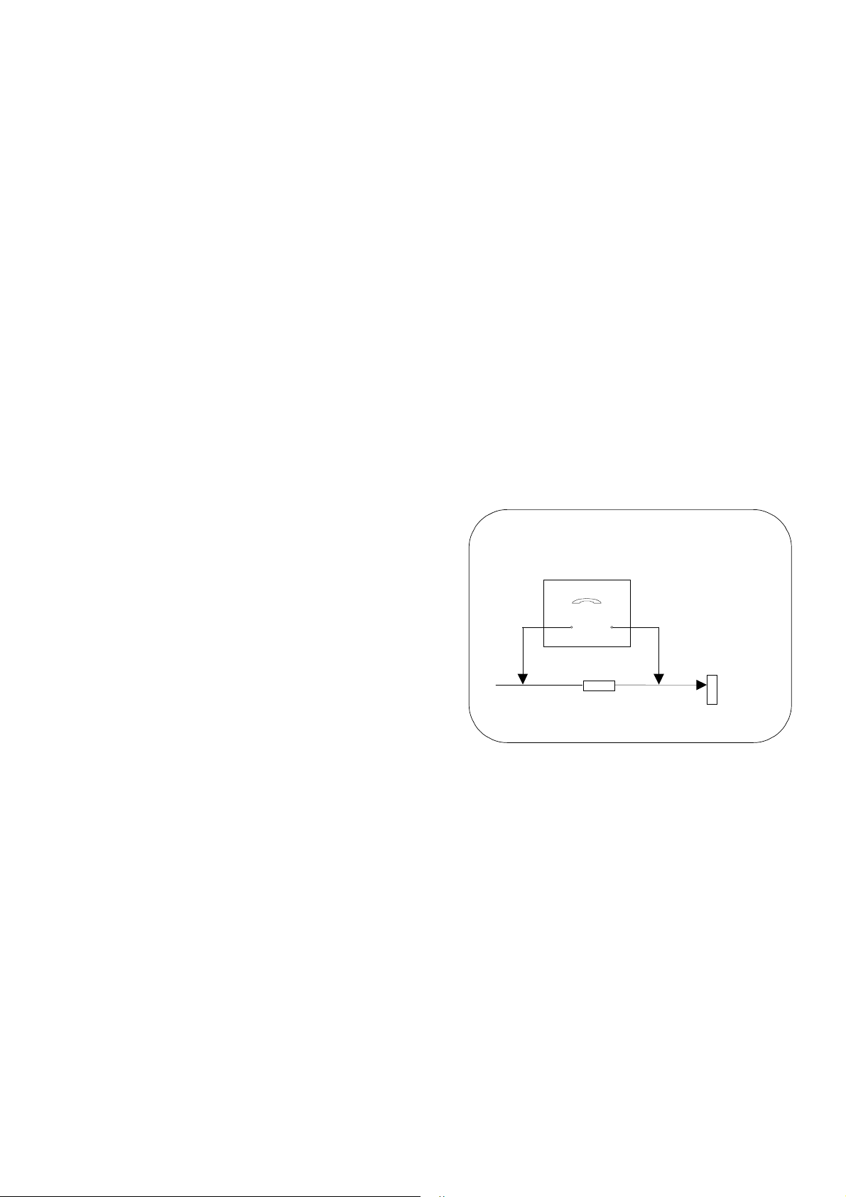
HOT CHECK CIRCUIT
a.c. VOLTMETER
WATER PIPE
(
EARTH)
TO INSTRUMENT'S EXPOSED
METALLIC PARTS
Fig. 1.
2k
Ω
ΩΩ
Ω
10 Watts
2
SERVICE HINTS
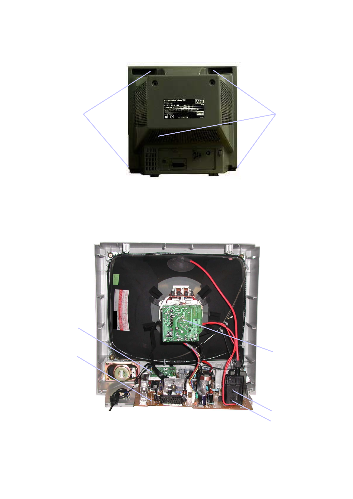
How to remove the rear cover
1. Remove the 5 screws as shown in Fig.2.
LOCATION OF CONTROLS
3
Fig. 2.
SCREWS
SCREWS
Focus
Screen
CRT Board
Main Board
AV Board

ALIGNMENT PROCEDURE AND OPTION SETTING
Entering SERVICE mode
Service mode is entered by selecting the “mute” remote key and local “down” simultaneously with the sharpness DAC set to
Minimum and programme position 99 selected.
Service mode 2 is selected by pressing the Recall remote key while in service mode 1.
Service mode navigation
- Up /Down remote keys :cycle through the service items available.
- -/+ remote keys :Decrement/Increment the values within range.
- TV/AV :Store the current data.
- 0 – 7 digit keys :Toggle bits 0-7 in option byte (service mode 2).
Order
Item
Range
1
Cut off (VG2)
LED ON , LED OFF
2
Vertical slope
0-63
3 Vertical Shift 0-63
4 Vertical amplitude 0-63
5 Horizontal shift 0-63
6 Red Cut 0-63
7 Green Cut 0-63
8 Red Drive 0-63
9 Green Drive 0-63
10 Blue Drive 0-63
11 AGC 0-63
12 Sub-Colour 0-63
13 Sub-Brightness 0-63
Sub-Colour: Set sub-colour to 16.
Sub-Brightness: Set sub-colour to 33.
G2 alignment: Before entering into service mode, recall the nominal picture setting :remote key “N”.
From this setting, increase brightness by 11 steps and reduce sharpness to minimum.
Tune a colour bar signal on Prg 99 and enter into SVC mode. In SVC mode , select “G2” item
and press – or + remote key to control software disable vertical deflection. The user must then
adjust G2 voltage on FBT, to find the point where LED is ON. Press – or + remote key to return
to normal SVC mode.
White balance: - Select a dark picture and adjust Red Cut and Green Cut to the desired colour temperature.
- Select a bright picture, set Blue Drive to 32 and adjust Red Drive, and Green Drive to the
desired colour temperature.
4

SOUND AMP
IC1001
AN7523
6
2
1
3
4
2
6
7
5
1
HEADPHONE_JACK
J1001
SPEAKER
SP351
4
SOUND+B
NC
+
BLOCK DIAGRAM
E-1
E-2
MICON/CHROMA
IC101 TDA9361_401-61
SDA
3
SCL
2
SDA
5
SCL
6
56
54
64
61
58
LED1
3.3V(A)
VDD
Vddp
IR
X_TAL
59
X_TAL
X101
12MHz
D101
1
OS101
7
KEY_IN
STR
FUNCTION
10
UP
DOWN
TU001
V.OUTPUT
IC401 TDA8357J
FB401
7
1
5
4
11
SCL SDA BPL AGC
IF
24
23
6
P.CON+5V
RF_AGC
IF1
IF2
V-
21
2
INB
7
OUTA
J801
6
8
11
F
7
DY
1
F
S
2
3
HV
+B
H.DRV+B
V+
22
1
INA
39
14
Vp1
VCC
P.CON+8V
44
AM-OUT
TV/AV
EEPROM
IC199
S-24C16AFJA-TB-01
J701
2
6
47
46
48
28
35
11
7
15
R_IN
G_IN
B_IN
3
1
AUDIO_OUT
EXT.A.IN
Q601
BUFFER
12
FRONT VIDEO
J702
1
2
FRONT AUDIO
J703
H_OUT
33
Q401
H.OUTPUT
Q405
H.DRIVE
VIDEO AMP
IC801 TDA6107Q
CRT
V801
8
7
9
VOC(3)
VOC(2)
VOC(1)
VI(1)
VI(2)
VI(3)
2
1
3
52
53
51
B_OUT
G_OUT
R_OUT
6
180V
42
CVBS/Yin
-
6VDD
180V
T502
T501
18
17
1
3
5V REG. IC
IC501 KIA7805API
1
3
8V REG. IC
IC502 KIA7808API
14
12
+B
SOUND+B
P.CON+8V
P.CON+5V
AT+5.6V
D501, D502
D503, D504
PELAY
RY501
AC220-240V
50Hz
D529, D532
D533, D534
AT3.5V
AT3.5V
8
8
6
1
4
Q602
BUFFER
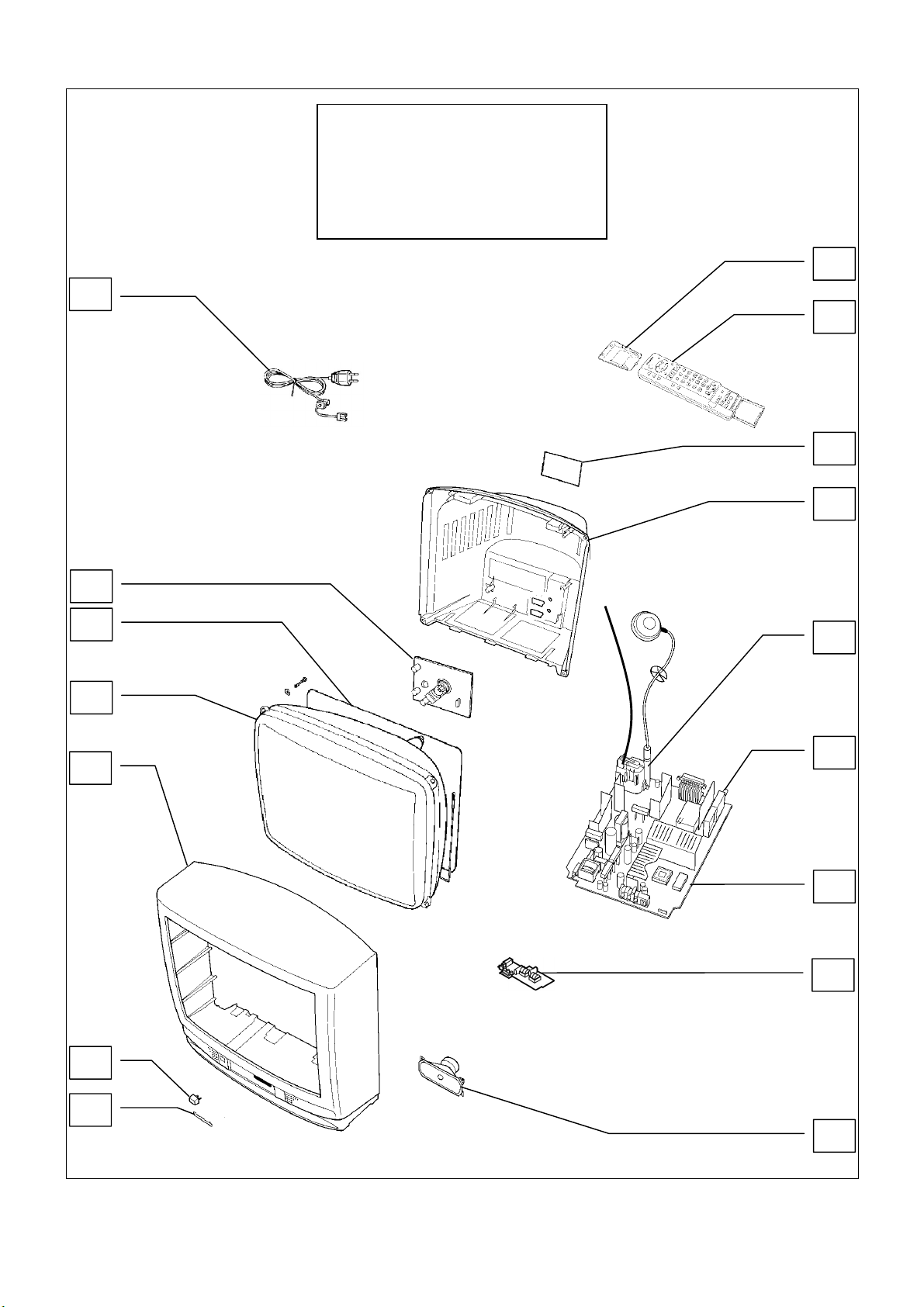
PARTS LOCATION
7
9
1
6
14
16
4
12
7
15
13
5
8
11
NOTE:
The numbers on the exploded view below
refer to the mechanical section of the
Replacement Parts List.
This diagram is used for representative
purposes only.
2
10
3
 Loading...