


SPECIFICATIONS
(Information in brackets{ } refers to model TX-25CK1F) (Information in brackets[ ] refers to model TX-21CK1F)
Power Source: |
220-240V a.c., 50Hz |
||
Power Consumption: |
76W |
{76W} |
[60W] |
Aerial Impedance: |
75Ω unbalanced, Coaxial Type |
||
Standby Power |
|
|
|
Consumption: |
0,9W |
{0,9W} |
[1W] |
Receiving System: |
PAL B/G, PAL-60 |
|
|
|
SECAM B/G, SECAM L, SECAM L’ |
||
|
M.NTSC (AV) |
|
|
Receiving Channels: |
NTSC (AV only) |
|
|
|
|
|
|
VHF E2-E12 |
VHF H1-H2 (ITALY) |
||
VHF A-H (ITALY) |
VHF R1-R2 |
|
|
VHF R3-R5 |
VHF R6-R12 |
|
|
UHF E21-E69 |
CATV (S01-S05) |
|
|
CATV S1-S10 (M1-M10) |
CATV S11-S20 (U1-U10) |
||
CATV S21-S41 (HYPERBAND) |
|
|
|
Intermediate Frequency: |
|
|
|
Video |
38,9MHz, 33,9MHz |
||
Sound |
33,4MHz, 33,16MHz (A2) |
||
|
33,05MHz (NICAM) |
||
|
32,4MHz, 33,05MHz (L NICAM) |
||
|
40,4MHz, 39,75MHz (L’ NICAM) |
||
Colour |
34,47MHz, 34,5MHz, 34,65MHz |
||
|
38,3MHz, 38,15MHz |
||
Video/Audio Terminals: |
|
|
|
AV1 IN |
Video (21 pin) |
1V p-p 75Ω |
|
|
Audio (21 pin) |
500mV rms 10kΩ |
|
|
RGB (21 pin) |
0,7V p-p 75Ω |
|
AV1 OUT |
Video (21 pin) |
1V p-p 75Ω |
|
|
Audio (21 pin) |
500mV rms 1kΩ |
|
AV FRONT |
Video (21 pin) |
1V p-p 75Ω |
|
|
Audio (21 pin) |
500mV rms 10kΩ |
|
High Voltage: |
28kV +0,7kV -1kV {28kV +0,7kV -1kV} |
||
|
[27kV +0,7kV -1kV] |
||
Picture Tube: |
A66ECF50X04 |
63cm |
|
|
{A59ECF50X04 |
59cm} |
|
|
[A51EER35X80 |
51cm] |
|
Audio Output: |
2 x 10W (Music Power) |
||
|
2 x 5W (R.M.S.) |
|
|
|
8Ω Impedance |
|
|
Headphones: |
8Ω Impedance |
|
|
Accessories supplied: |
Remote Control |
|
|
Dimensions: |
2 x R6 (UM3) Batteries |
||
|
|
|
|
Height: |
580mm |
{538mm} |
[476mm] |
Width: |
646mm |
{580mm} |
[512mm] |
Depth: |
471mm |
{442,5mm} [470mm] |
|
Net Weight: |
33kg |
{27kg} |
[20,6kg] |
Specifications are subject to change without notice.
Weights and dimensions shown are approximate. NOTE: This Service Manual should be used in conjunction with the Z8 technical guide.
ORDER No. 99-SM-011
Colour Television
TX-28CK1F
TX-25CK1F
TX-21CK1F
Z8 Chassis
CARACTÉRISTIQUES
(L' information entre parenthéses { } se rapporte au modéle TX-25CK1F suivant)
(L' information entre parenthéses [ ] se rapporte au modéle TX-21CK1F suivant)
Alimentation:
Consommation: Impédance d'antenne: Standby Consommation: Systéme de réception:
Canaux de réception:
VHF E2-E12
VHF A-H (ITALY)
VHF R3-R5
UHF E21-E69
CATV S1-S10 (M1-M10)
CATV S21-S41 (HYPERBAND)
Fréquency Intermédiaire:
Video
Sound
Couleur
Les bornes vidéo/audio:
Entrée AV1 (21 brioches)
Sorties AV1 (21 brioches)
AV FRONT (21 brioches)
Tension d'anode:
Tube image:
Sortie Audio:
Casque d'écoute:
Accessories fournis:
Dimensions: |
|
|
|
Hauteur: |
580mm |
{538mm} |
[476mm] |
Largeur: |
646mm |
{580mm} |
[512mm] |
Profondeur: |
471mm |
{442,5mm} |
[470mm] |
Poids (NET): |
33kg |
{27kg} |
[20,6kg] |
Les caractéristiques techniques sont susceptibles de modification sans Préavis. Le poids et les dimensions indiqués sont approximatifs.
Note: Ce manuel de service doit etre utilise avec le guide technique Z8.
CONTENTS |
|
SAFETY PRECAUTIONS .................................................... |
2 |
SERVICE HINTS ................................................................. |
4 |
SELF CHECK ...................................................................... |
5 |
ADJUSTMENT PROCEDURE ............................................. |
6 |
WAVEFORM PATTERN TABLE .......................................... |
7 |
ALIGNMENT SETTINGS ..................................................... |
8 |
BLOCK DIAGRAMS............................................................. |
10 |
PARTS LOCATION.............................................................. |
13 |
REPLACEMENT PARTS LIST............................................. |
14 |
SCHEMATIC DIAGRAMS.................................................... |
22 |
CONDUCTOR VIEWS ......................................................... |
27 |
SAFETY PRECAUTIONS |
|
GENERAL GUIDE LINES
1.It is advisable to insert an isolation transformer in the a.c. supply before servicing a hot chassis.
2.When servicing, observe the original lead dress in the high voltage circuits. If a short circuit is found, replace all parts which have been overheated or damaged by the short circuit.
3.After servicing, see that all the protective devices such as insulation barriers, insulation papers, shields and isolation R-C combinations are correctly installed.
4.When the receiver is not being used for a long period of time, unplug the power cord from the a.c. outlet.
5.Potentials as high as 28,7kV {28,7kV} [27,7kV] are present when this receiver is in operation. Operation of the receiver without the rear cover involves the danger of a shock hazard from the receiver power supply. Servicing should not be attempted by anyone who is not familiar with the precautions necessary when working on high voltage equipment. Always discharge the anode of the tube.
6.After servicing make the following leakage current checks to prevent the customer from being exposed to shock hazard.
LEAKAGE CURRENT COLD CHECK
1.Unplug the a.c. cord and connect a jumper between the two prongs of the plug.
2.Turn on the receiver’s power switch.
3.Measure the resistance value with an ohmmeter, between the jumpered a.c. plug and each exposed metallic cabinet part on the receiver, such as screw heads, aerials, connectors, control shafts etc. When the exposed metallic part has a return path to the chassis the reading should be between 4M ohm and 20M ohm. When the exposed metal does not have a return path to the chassis the reading must be infinite.
CONTENTS |
|
PRECAUTIONS DE SECURITE .......................................... |
2 |
SUGGESTIONS DE DEPANNAGE ..................................... |
4 |
AUTO TEST ........................................................................ |
5 |
REGLAGES......................................................................... |
6 |
TABLEAU DES OSCILLOGRAMMES.................................. |
7 |
REGLAGES......................................................................... |
9 |
SCHEMA SYNOPTIQUE ..................................................... |
10 |
EMPLACEMENT DES PIÈCES ........................................... |
13 |
LISTE DES PIÈCES DE RECHANGE.................................. |
14 |
DIAGRAMME SCHEMATIQUE............................................ |
22 |
VUE DU CIRCUIT IMPRIMÉ................................................ |
27 |
PRECAUTIONS DE SECURITE |
|
CONSEILS GENERAUX
1.Avant d'effectuer toute révision d'un châssis sous tension il est recommandé d'installer un transformateur d'isolation.
2.Il est important, lors des réparations, de conserver la position initial de tours les fils et faisceaux, surtout dans le circuit de la haute tension. Remplacer toutes les pièces affectées par la chaleur dégagée lors d'un cort-circuit.
3.Aprés les réparations, s'assurer que toutes les pièces protectrices telle que barrières ou papiers isolant, blindages et réseaux d'isolation R-C soient convenablement placées.
4.Il est préférable de débrancher le fil d'alimentation si la télé-couleur ne doit pas être utilisée pendant un certain temps.
5.Une tension élevée, de l'odre de 28,7kV {28,7kV} [27,7kV] est présente en plusieurs edroits lorsque l'appareil est en circuit. Il y a danger de chocs électriques lorsque le contact est établi en absence du panneau arrière. Toute personne qui tente de réparer cet appareil doit d'abord être consciente des précautions à observer avant de travailler sur un circuit à haute tension. Toujours décharger l'anode du tube cathodique au châssis avant de manipuler.
6.Aprés tout réparation, on doit effectuer les tests de courant de fuite dans le but d'éviter tout choc.
VERIFICATION DES COURANTS DE FUITE SANS ALIIMENTATION
1.Débrancher le fil d'alimetation et installer un fil STRAP entre les deux broches de la fiche.
2.Placer l'interrupteur comme pour établir le contact sur l'appareil.
3.Mesurer la résistance entre les branches de la fiche d'alimentation et les pièces métalliques visibles telles que têtes de vis, antennes, arbre des commandes, support des poignées, etc. Certaines de ces pièces sont en contact avec le châssis et la rèsistance measurée devrait se siture entre 4MΩ et 20MΩ. La résistance des pièces qui ne sont pas en contact avec le châssis doit être infinie.
2
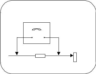
LEAKAGE CURRENT HOT CHECK
1.Plug the a.c. cord directly into the a.c. outlet. Do not use an isolation transformer for this check.
2.Connect a 2kΩ 10W resistor in series with an exposed metallic part on the receiver and an earth, such as a water pipe.
3.Use an a.c. voltmeter with high impedance to measure the potential across the resistor.
4.Check each exposed metallic part and check the voltage at each point.
5.Reverse the a.c. plug at the outlet and repeat each of the above measurements.
6.The potential at any point should not exceed 1,4 V rms. In case a measurement is outside the limits specified, there is a possibility of a shock hazard, and the receiver should be repaired and rechecked before it is returned to the customer.
HOT CHECK CIRCUIT
CIRCUIT DE VERIFICATION A CHAUD
To Instrument's |
a.c. Voltmeter |
|
Voltmetre c.a. |
Vers les parties |
|
exposed |
|
metallique exposees |
metallic parts |
|
de ll'instrument. |
|
|
WATER PIPE (EARTH) |
|
|
CONDUITE D'EAU |
|
2kΩ 10 Watts |
(TERRE) |
|
|
Fig. 1.
X-RADIATION WARNING
1.The potential sources of X-Radiation in TV sets are the high voltage section and the picture tube.
2.When using a picture tube test jig for service, ensure that the jig is capable of handling 28,7kV {28,7kV} [27,7kV] without causing X-Radiation.
NOTE : It is important to use an accurate periodically calibrated high voltage meter.
1.Set the brightness to minimum.
2.Measure the high voltage. The meter should indicate
TX-28,25CK1F |
28kV |
+0,7kV -1kV. |
TX-21CK1F |
27kV |
+0,7kV -1kV. |
If the meter indication is out of tolerance, immediate service and correction is required to prevent the possibility of premature component failure.
3.To prevent any X-Radiation possibility, it is essential to use the specified tube.
VERIFICATION A CHAUD DU
COURANT DE FUITE
1.Brancher le cordon secteur directement à une prise secteur. Ne pas utiliser de transformateur d'isolation pour cette vérification.
2.Raccorder une résistance de 2kΩ, 10W, en série avec une partie métallique exposée du récepteur et une terre comme une conduite d'eau.
3.Utiliser un voltmètre c.a., de type à impédance élevée, pour mesurer le potentiel à travers la résistance.
4.Vérifier toutes les parties métalliques exposées et mesurer la tension à chaque point.
5.Retourner la fiche c.a. dans la prise secteur et répéter toutes les mesures ci-dessus.
6.Le potentiel à tous les points ne doit pas dépasser 1,4 volt RMS. Au cas où une mesure est supérieure à cette limite spécifiée, il y a un risque de décharge électrique et le récepteur doit être réparé et revérifié avant d'être rendu au cliente.
IRRADIATION AUX RAYONS X ATTENTION :
1.Les parties de la haute tension et du tube-cathodique d'une télé-couleur sont des sources possible d'emissions de rayons X.
2.Si un tube cathodique témoin est utilisé pour la réparation, s'assurer que son assemblage pourra supporter 28,7kV {28,7kV} [27,7kV] sans, émettre de radiations.
REMARQUE : Il est important que le multimètre à haute tension utilisé soit étalonné périodiquement.
1.Tourner entièvers la gauche la commande de lumière.
2.Mesurer la haute tension à l'aide du multimètre approprié
TX-28,25CK1F |
28kV |
+0,7kV -1kV. |
TX-21CK1F |
27kV |
+0,7kV -1kV. |
La valeur nominale est de la lecture est hors des tolérances, une réparation immédiate s'impose afin de prévenir toute panne prématurée.
3.Il est essentiel d'utiliser le tube cathodique d'origine pour prévenir toute émission de rayons X.
3

SERVICE HINTS |
SUGGESTIONS DE DEPANNAGE |
HOW TO REMOVE THE REAR COVER |
COMMENT RETIRER LE PENNEAU ARRIÈRE |
1. Remove the 5 screws (A) as shown in Fig.2. |
1. Retirer les 5 vis (A) comme sur la Fig.2. |
|
Screws A |
|
Vis A |
|
Fig.2. |
LOCATION OF CONTROLS |
EMPLACEMENT DES |
|
COMMANDES |
Focus
Screen
E - Board Y - Board
Fig.3.
4

SELF CHECK |
AUTO TEST |
1.Self-check is used to automatically check the bus lines and hexadecimal code of the TV set.
2.To get into the Self-Check mode press the down
(-/v) button on the customer controls at the front of the set,at the same time pressing the STATUS button on the remote control, and the screen will show :-
1.L'auto test est utilísé pour vérifier les BUS et les codes Hexadécimaux du TV.
2.Pour renter dans le mode Auto Test presser le bouton STATUS  de la télécommande et simultanément le bouton (-/v) en face avant du TV. Le menu Auto Test s'affiche :-
OPTION1 |
6D |
{OPTION1 6D} |
[OPTION1 |
4D] |
OPTION2 |
00 |
{OPTION2 00} |
[OPTION2 |
00] |
Service Aids |
Aides Techniques |
To aid in the service of our current chassis there are a number |
Pour faciliter le dépannage des modèles courants il'y-a un |
of Service Aids, which have been made available. |
certain nombres d'outils de service disponibles. |
• LUCI interface kit (Linked Utility Computer Interface)Part |
• Interface LUCI (Linked Utility Computer Interface) |
number: TZS6EZ002 |
Ref: TZS6EZ002 |
This contains interface and cables for connecting TV |
Cette référence contient; L'interface et les cables de |
service connector and a PC as well as diagnostic |
connexion aux TV et PC et également le logiciel de |
software. As new models are introduced upgrade |
diagnostic. ( A l'introduction des nouveaux modèles un |
software will become available. |
logiciel remis à jour sera disponible ). |
• VICI (Visual Interactive Computer Information) |
• VICI (Visual Interactive Computer Information) |
These C.D.'s contain multimedia documentation providing |
Ces céderom contienent des documents multimédias |
quick access to service information. |
donnant acces rapide aux informations de Service. |
Part No. TZS7EZ006, TZS7EZ005 & TZS8EZ001 |
Ref. TZS7EZ006, TZS7EZ005 & TZS8EZ001 |
1. Service Manuals |
1. Les schémas techniques |
2. Instruction Books |
2. Les modes d'emplois |
3. Technical Information |
3. Les informations techniques |
• TASMIN (Technically Advanced System for Multimedia |
• TASMIN (Technically Advanced System for Multimedia |
Interactive Notes) |
Interactive Notes) |
As well as providing a first step towards more interactive |
C'est le premier pas vers un "training" plus interactif, ce |
training this product also achieves quick access to |
produit permet aussi bien un acces rapide aux |
Technical Information. |
informations techniques. |
5
ADJUSTMENT PROCEDURE
|
|
Item/Preparation |
|
|
Adjustments |
|
|
|||
|
|
+B SET-UP |
1. Confirm the following voltages: |
|
|
|
||||
1. |
Receive a Greyscale signal. |
|
|
|
||||||
2. |
Set the controls:- |
+B1 |
3,3 |
± |
0,3V |
+B13 |
-13 |
± |
1V |
|
|
|
|
+B2 |
195 |
± |
10V |
+B14 |
27,5 |
± |
1,5V |
|
Brightness |
Minimum |
|
{195 |
± |
10V} |
|
{27,5 |
± |
1,5V} |
|
|
|
+B3 |
[190 |
± |
10V] |
+B15 |
[27,5 |
± |
1,5V] |
|
Contrast |
Minimum |
13,5 |
± |
1V |
28 |
± |
1,5V |
||
|
|
|
|
{13,5 |
± |
1V} |
|
{28 |
± |
1,5V} |
|
Volume |
Minimum |
+B4 |
[12,5 |
± |
1V] |
+B16 |
[28 |
± |
1,5V] |
|
|
|
10 |
± |
1V |
11,5 |
± |
1V |
||
|
|
|
+B8 |
5 |
± |
0,3V |
|
{11,5 |
± |
1V} |
|
|
|
+B11 147 |
± |
10V |
|
[11,5 |
± |
1V] |
|
|
|
|
|
{147 |
± |
10V} |
+B17 8 |
± |
1V |
|
|
|
|
|
[127 |
± |
10V] |
+B18 |
5 |
± |
0,3V |
|
|
|
|
|
|
|
|
|
|
|
|
Cut-Off / Ug2 Adjustment |
Set Contrast on maximum, set Brightness on centre, |
||||||||
1. |
Receive a Greyscale signal. |
|||||||||
2. |
Degauss the tube externally. |
switch on AV mode. |
|
|
|
|
|
|||
3. |
Set the TV into Service Mode 1. |
Enter Service mode. Set Sub-Brightness to 31. |
||||||||
4. |
Select Ug2 test. |
Select Ug2.Press "+" and adjust screen Vr till sharp vertical |
||||||||
|
|
|
line is visible and LED switches off. Then reduce screen Vr |
|||||||
|
|
|
till LED is just switched on(pin6 of connector E6 must be |
|||||||
|
|
|
connected to GND). |
|
|
|
|
|
||
Note: To set up ”white balance” first set up “Cut off” register to 8. Then set up “high-light” with the help of “drive” registers. Finish setting-up of “Low-light” with the help of ”Cut-off” register.
Carry out setting-up of ”white balance” in available TV systems (PAL, SECAM).
REGLAGES
|
|
Préparation |
|
|
|
Réglages |
|
|
||
|
|
+B Réglages |
1. .Confirmer le réglage: |
|
|
|
|
|||
1. |
Recevoir le signal Greyscale. |
+B1 |
3,3 |
± |
0,3V |
+B13 |
-13 |
± |
1V |
|
2. |
Régler les contrôles suivants |
+B2 |
195 |
± |
10V |
+B14 |
27,5 |
± |
1,5V |
|
|
|
|
|
{195 |
± |
10V} |
|
{27,5 |
± |
1,5V} |
|
Lumière |
Minimum |
+B3 |
[190 |
± |
10V] |
+B15 |
[27,5 |
± |
1,5V] |
|
|
|
13,5 |
± |
1V |
28 |
± |
1,5V |
||
|
Contraste |
Minimum |
|
{13,5 |
± |
1V} |
|
{28 |
± |
1,5V} |
|
|
|
+B4 |
[12,5 |
± |
1V] |
+B16 |
[28 ± |
1,5V] |
|
|
Volume |
Minimum |
10 |
± |
1V |
11,5 |
± |
1V |
||
|
|
|
+B8 |
5 |
± |
0,3V |
|
{11,5 |
± |
1V} |
|
|
|
+B11 147 |
± |
10V |
|
[11,5 |
± |
1V] |
|
|
|
|
|
{147 |
± |
10V} |
+B17 8 |
± |
1V |
|
|
|
|
|
[127 |
± |
10V] |
+B18 |
5 |
± |
0,3V |
|
|
|
|
|||||||
|
|
Cut-Off / Ug2 Adjustment |
Ajuster le contraste au maximum, ajuster la clarté au |
|||||||
1. |
Recevoir le signal Greyscale . |
centre, commuter au "AV" mode. Entrer dans le mode de |
||||||||
2. |
Démagnétiser le tube extérieurement. |
service. Ajuster la sub-brightness á la valeur 31. Choisir |
||||||||
3. |
Mettre le TV en Mode Service 1. |
Ug2. Appuyer "+" et ajuster le screen "Vr" de sorte que la |
||||||||
4. |
Sélectionner le Mode Ug2 Test. |
linge ténue verticale soit nettement visible et que LED |
||||||||
|
|
|
s´arręte. Ensuite diminuer le screeen "Vr" jusq´á ce que |
|||||||
|
|
|
LED s´allume(pin6 du connecteur doit être reliè à la terre). |
|||||||
Note: Pour ajuster “white balance“ ramener tout d´abord le registre “Cut off“ à 8. Puis, à l´aide des registres “drive“ ajuster “high-light“. Terminer la régulation de “Low-Light“ à l´aide du registre “Cut off“.
Effectuer la mise au point de “white balance“ dans les TV systémes abordables (PAL, SECAM).
6
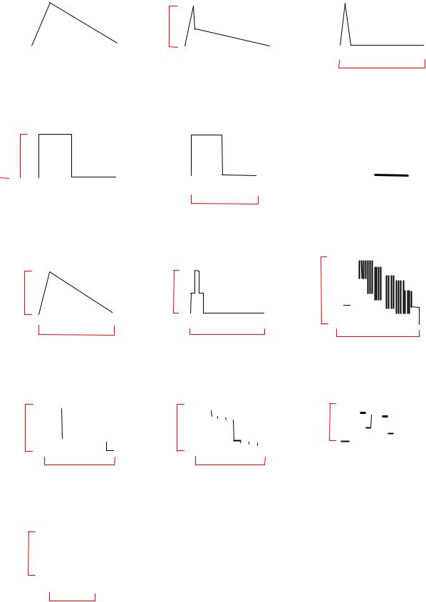
WAVEFORM PATTERN TABLE TABLEAU DES OSCILLOGRAMMES
|
IC 601 |
|
|
|
|
|
|
|
|||
|
|
|
|
VERT - OUT |
|
||||||
|
Pin 21 |
|
|
|
|
||||||
|
|
|
|
|
|
|
|
||||
|
|
|
|
|
|
|
|
|
|
|
|
|
|
|
|
|
|
|
|
|
|
|
|
|
|
|
|
|
|
|
|
|
|
||
|
|
|
|
|
|
|
|
|
|
|
|
|
1V |
|
|
|
|
|
|
|
|
|
|
|
|
|
|
|
|
|
|
|
|||
|
|
|
|
|
|
|
|
|
|
|
|
|
|
|
|
|
|
|
|
|
|
|
|
|
|
|
|
|
|
|
20ms |
|
|
||
|
|
|
|
|
|
|
|
||||
|
|
|
|
|
|
|
|
|
|
|
|
|
|
|
|
|
|
|
|
|
|
|
|
|
|
|
|
|
|
|
|
|
|
|
|
|
|
IC 601 |
|
|
|
|
|
|
|
|
|
H - OUT |
|
|
|||||||||||||||||
|
|
Pin 33 |
|
|
|
|
|
|
|
|
|
|
|
|
|
|
|
|
|
|
|
|
|
|
|
||||||
|
|
3V |
|
|
|
|
|
|
|
|
|
|
|
|
|
|
|
|
|
|
|
|
|
|
|
|
|
|
|
|
|
|
|
|
|
|
|
|
|
|
|
|
|
|
|
|
|
64 s |
|
|
|
|
|
|
|
|
|
|
|
||||
|
|
|
|
|
|
|
|
|
|
|
|
|
|
|
|
|
|
|
|
|
|
|
|
|
|
|
|||||
|
|
|
|
|
|
|
|
|
|
|
|
||||||||||||||||||||
|
|
|
|
|
|
|
|
|
|
|
|
|
|
|
|
|
|
|
|
|
|
|
|
|
|
|
|
|
|
|
|
|
|
|
|
|
|
|
|
|
|
|
|
|
|
|
|
|
|
|
|
|
|
|
|
|
|
|
|
|
|
|
|
|
|
|
|
|
|
|
|
|
|
|
|
|
|
|
|
|
|
|
|
|
|
|
|
|
|
|
|
|
|
|
|
|
|
IC 701 |
|
|
|
|
|
|
|
|
|
|
|
|
|
|
|
|
|
HFLB |
|
||||||||||
|
|
Pin 8 |
|
|
|
|
|
|
|
|
|
|
|
|
|
|
|
|
|
|
|
|
|
|
|
|
|||||
|
|
|
|
|
|
|
|
|
|
|
|
|
|
|
|
|
|
|
|
|
|
|
|
|
|||||||
|
|
|
|
|
|
|
|
|
|
|
|
|
|
|
|
|
|
|
|
|
|
|
|
|
|
|
|
|
|
||
|
|
2V |
|
|
|
|
|
|
|
|
|
|
|
|
|
|
|
|
|
|
|
|
|
|
|
|
|
|
|||
|
|
|
|
|
|
|
|
|
|
|
|
|
|
|
|
|
|
|
|
|
|
|
|
|
|
|
|
|
|||
|
|
|
|
|
|
|
|
|
|
|
|
|
|
|
|
|
|
|
|
|
|
|
|
|
|
|
|
|
|
|
|
|
|
|
|
|
|
|
|
|
|
|
|
|
|
|
|
64 s |
|
|
|
|
|
|
|
|
|||||||
|
|
|
|
|
|
|
|
|
|
|
|
|
|
|
|
|
|
|
|
|
|
|
|
|
|
|
|
|
|
|
|
|
|
|
|
|
|
|
|
|
|
|
|
|
|
|
|
|
|
|
|
|
|
|
|
|
|
|
|
|
|
|
|
|
|
|
|
|
|
|
|
|
|
|
|
|
|
|
|
|
|
|
|
|
|
|
|
|
|||||||
|
|
IC 601 |
|
|
|
|
|
|
|
|
|
|
|
|
|
R - OUT |
|
||||||||||||||
|
|
Pin 51 |
|
|
|
|
|
|
|
|
|
|
|
|
|
|
|
|
|
|
|
|
|
|
|
|
|||||
|
|
|
|
|
|
|
|
|
|
|
|
|
|
|
|
|
|
|
|
|
|
|
|
|
|||||||
|
|
|
|
|
|
|
|
|
|
|
|
|
|
|
|
|
|
|
|
|
|
|
|
|
|
|
|
||||
|
|
|
|
|
|
|
|
|
|
|
|
|
|
|
|
|
|
|
|
|
|
|
|
|
|
|
|||||
|
|
2,7V |
|
|
|
|
|
|
|
|
|
|
|
|
|
|
|
|
|
|
|
|
|
|
|
|
|
|
|
|
|
|
|
|
|
|
|
|
|
|
|
|
|
|
|
|
|
|
|
|
|
|
|
|
|
|
|
|
|
|
|
||
|
|
|
|
|
|
|
|
|
|
|
|
|
|
|
|
|
|
|
|
|
|
|
|
|
|
|
|
||||
|
|
|
|
|
|
|
|
|
|
|
|
|
|
|
|
|
|
|
|
|
|
|
|
|
|
|
|
|
|
|
|
|
|
|
|
|
|
|
|
|
|
|
|
|
|
|
64 s |
|
|
|
|
||||||||||||
|
|
|
|
|
|
|
|
|
|
|
|
|
|
|
|
|
|
|
|||||||||||||
|
|
|
|
|
|
|
|
|
|
|
|
|
|
|
|
|
|
|
|
|
|
|
|
|
|
|
|
|
|
|
|
|
|
|
|
|
|
|
|
|
|
|
|
|
|
|
|
|
|
|
|
|
|
|
|
|
|
|
|
|
|
|
|
IC 451 |
|
|
|
|
|
|
|
|
|
|
|
|
VERT - DRIVE |
|
|||||
Pin 2 |
|
|
|
|
|
|
|
|
|
|
|
|
|
|
|
|
|
|
|
|
|
|
|
|
|
|
|
|
|
50V |
|
|
|
|
|
|
|
|
|
|
|
|
|
|
|
|
|
|
|
|
|
|
|
|
|
|
|
|
|
|
|
|
|
|
20ms |
|
|
|
|
|
|
|
|
|
|
|
|||
|
|
|
|
|
|
|
|
|
|
|
|
|
|
|
|
|
|
|
|
|
|
|
|
|
|
|
|
|
|
|
IC 701 |
|
|
|
|
|
|
|
|||
|
|
|
|
EW - OUT |
|
||||||
|
Pin 5 |
|
|
|
|
|
|
|
|||
|
|
|
|
|
|
||||||
|
|
|
|
|
|
|
|
|
|
|
|
|
|
|
|
|
|
|
|
|
|
|
|
|
20V |
|
|
|
|
|
|
|
|
|
|
|
|
|
|
|
|
||||||
|
|
|
|
|
|
|
|
|
|||
|
|
|
|
|
|
|
|
|
|
|
|
|
|
|
|
|
|
|
|
|
|
|
|
|
|
|
|
|
|
|
64 s |
|
|
||
|
|
|
|
|
|
|
|
|
|
|
|
|
|
|
|
|
|
|
|
|
|
|
|
|
|
|
|
|
|
|
|
|
|
IC 601 |
|
|
FBI/SCO |
||
|
|
Pin 34 |
|
|
|
|
|
|
|
|
|
||||
|
|
|
|
|
|
|
|
|
|
|
|
|
|
|
|
|
|
5,7V |
|
|
|
|
|
|
|
|
|
|
|
||
|
|
|
|
|
|
|
|
|
|
|
|
|
64 s |
|
|
|
|
|
|
|
|
|
|
|
|
|
|
|
|
|
|
|
|
|
|
|
|
|
|
|
|
|
|
|
|
|
|
|
|
|
|
|
|
|
IC 601 |
|
|
|
|
|
|
|
|
|
|
G - OUT |
|||||||||
|
Pin 52 |
|
|
|
|
|
|
|
|
|
|
|
|
|
|
|
|
|
|
|
|
|
|
|
|
|
|
|
|
|
|
|
|
|
|
|
|
|
|
|
|||
|
|
|
|
|
|
|
|
|
|
|
|
|
|
|
|
|
|
|
|
|
|
|
|
|
|
|
|
|
|
|
|
|
|
|
|
|
|
|
|
|
|
|
|
|
2,7V |
|
|
|
|
|
|
|
|
|
|
|
|
|
|
|
|
|
|
|
|
|
|
|
|
|
|
|
|
|
|
|
|
|
|
|
|
|
|
|
|
|
|
|
|
|
|
|
|
|
|
|
|
|
|
|
|
|
|
|
|
|
|
||
|
|
|
|
|
|
|
|
|
|
|
|
|
|
|
|
|
|
|
|
|
|
|
|
|
|
|
|
|
|
|
|
64 s |
|
|
|
|
|
|
|
||||
|
|
|
|
|
|
|
|
|
|
|
|
|
|
|
|
|
|
|
|
|
|
|
|
|
|
|
|
|
|
|
|
|
|
|
|
|
|
|
|
|
|
|
|
|
|
|
|
|
|
|
|
|
|
|
|
|
IC 451 |
|
|
|
|
|
|||
|
|
|
|
VFLB |
|
|||||
|
|
Pin 3 |
|
|
|
|
|
|||
|
|
|
|
|
|
|||||
|
|
|
|
|
|
|
|
|
|
|
|
|
|
|
|
|
|
|
|
|
|
|
|
|
|
|
|
|
|
|
|
|
|
|
28,4V |
|
|
|
|
|
|
|
|
|
|
|
|
|
|
|
|
|
||
|
|
|
|
|
|
|
|
|
|
|
|
|
|
|
|
|
|
|
|
|
|
|
|
|
|
|
|
|
20ms |
|
|
|
|
|
|
|
|
|
|
|
|
|
|
|
|
|
|
|
|
|
|
|
|
|
|
|
|
|
|
|
|
|
|
|
|
|
|
|
|
|
|
|
|
|
|
|
|
|
|
|
|
|
|
|
|
|
|
|
|
Base Q501 |
|
|
|
|
|
|
|
|
|
|
H - PULSE |
|
|
|||||||||||||||||
|
|
|
|
|
|
|
|
|
|
|
|
|
|
|
|
|
|
|
|
|
|
|
|
|
|
|
|
|
|
|
|
|
|
|
|
|
|
|
|
|
|
|
|
|
|
|
|
|
|
|
|
|
|
|
|
|
|
|
|
|
|
|
|
|
|
|
|
|
|
|
|
|
|
|
|
|
|
|
|
|
|
|
|
|
|
|
|
|
|
|
|
|
|
|
|
|
|
|
|
|
|
|
|
|
|
|
|
|
|
|
|
|
|
|
|
|
|
|
|
|
|
|
|
|
|
|
|
|
|
|
|
|
|
|
1,4V |
|
|
|
|
|
|
|
|
|
|
|
|
|
|
|
|
|
|
|
|
|
|
|
|
|
|
|
|
|
|
|
|
|
|
|
|
|
|
|
|
|
|
|
|
|
|
|
|
|
|
|
|
|
|
|
|
|
|
|
|
|
|
|
|
|
|
|
|
|
|
|
|
|
|
|
|
|
|
|
|
|
|
|
|
|
|
|
|
|
|
|
|
|
|
|
|
|
|
|
|
|
|
|
|
|
|
|
|
|
|
|
|
|
|
|
|
|
|
|
|
|
|
|
|
|
|
|
|
|
|
|
|
|
|
|
|
|
|
|
|
|
|
64 s |
|
|
|
|
|
|
|
|
|
|
|
|
||||||
|
|
|
|
|
|
|
|
|
|
|||||||||||||||||||||||
|
|
|
|
|
|
|
|
|
|
|
|
|
|
|
|
|
|
|
|
|
|
|
|
|
|
|
|
|
|
|
|
|
|
|
|
|
|
|
|
|
|
|
|
|
|
|
|
|
|
|
|
|
|
|
|
|
|
|
|
|
|
|
|
|
|
|
|
|
|
|
|
|
|
|
|
|
|
|
|
|
|
|
|
|
|
|
|
|
|
|
|
|
|
|
|
|
|
|
|
|
|
|
|
|
|
|
|
|
|
|
|
|
|
|
|
|
|
|
|||||||||||||
|
|
IC601 |
|
|
|
|
|
|
|
|
|
|
VIDEO OUT |
|
||||||||||||||||||
|
|
Pin 38 |
|
|
|
|
|
|
|
|
|
|
|
|
|
|
|
|
|
|
|
|
|
|
|
|
|
|||||
|
|
|
|
|
|
|
|
|
|
|
|
|
|
|
|
|
|
|
|
|
|
|
|
|
|
|
|
|
|
|||
|
|
|
2,7 V |
|
|
|
|
|
|
|
|
|
|
|
|
|
|
|
|
|
|
|
|
|
|
|
|
|
|
|
||
|
|
|
|
|
|
|
|
|
|
|
|
|
|
|
|
|
|
|
|
|
|
|
|
|
|
|
|
|
|
|||
|
|
|
|
|
|
|
|
|
|
|
|
|
|
|
|
|
|
|
|
|
|
|
|
|
|
|
|
|
|
|||
|
|
|
|
|
|
|
|
|
|
|
|
|
|
|
|
|
|
|
|
|
|
|
|
|
|
|
|
|
|
|||
|
|
|
|
|
|
|
|
|
|
|
|
|
|
|
|
|
|
|
|
|
|
|
|
|
|
|
|
|
||||
|
|
|
|
|
|
|
|
|
|
|
|
|
|
|
|
|
|
|
||||||||||||||
|
|
|
|
|
|
|
|
|
|
|
|
|
|
|
|
|
|
|
||||||||||||||
|
|
|
|
|
|
|
|
|
|
|
|
|
|
|
|
|
|
|
|
|
|
|
|
|
|
|
|
|
|
|
|
|
|
|
|
|
|
|
|
|
|
|
|
|
|
|
|||||||||||||||||||
|
|
|
|
|
|
|
|
|
|
|
|
|
64 s |
|
|
|||||||||||||||||
|
|
|
|
|
|
|
|
|
|
|
|
|
|
|
|
|
|
|
|
|
|
|
|
|
|
|
|
|
||||
|
|
|
|
|
|
|
|
|
|
|
|
|
|
|
|
|
|
|
|
|
|
|
|
|
|
|
|
|
|
|
|
|
|
|
|
IC 601 |
|
|
|
|
|
|
|
|
|
|
|
|
B - OUT |
|
|||||||||||||||
|
|
|
Pin 53 |
|
|
|
|
|
|
|
|
|
|
|
|
|
|
|
|
|
|
|
|
|
|
|
|
|||||
|
|
|
|
|
|
|
|
|
|
|
|
|
|
|
|
|
|
|
|
|
|
|
|
|
|
|||||||
|
|
|
|
|
|
|
|
|
|
|
|
|
|
|
|
|
|
|
|
|
|
|
|
|
|
|
|
|
|
|
||
|
|
|
|
|
|
|
|
|
|
|
|
|
|
|
|
|
|
|
|
|
|
|
|
|
|
|
|
|
|
|
||
|
|
|
2,7V |
|
|
|
|
|
|
|
|
|
|
|
|
|
|
|
|
|
|
|
|
|
|
|
|
|
|
|
|
|
|
|
|
|
|
|
|
|
|
|
|
|
|
|
|
|
|
|
|
|
|
|
|
|
|
|
|
|
|
|
|||
|
|
|
|
|
|
|
|
|
|
|
|
|
|
|
|
|
|
|
|
|
|
|
|
|
|
|
|
|
|
|||
|
|
|
|
|
|
|
|
|
|
|
|
|
|
|
|
|
|
|
|
|
|
|
|
|
|
|||||||
|
|
|
|
|
|
|
|
|
|
|
|
|
|
|
|
|
|
|
|
|
|
|
|
|
|
|||||||
|
|
|
|
|
|
|
|
|
|
|
|
|
|
|
|
|
|
|
|
|
|
|
|
|
|
|
|
|
||||
|
|
|
|
|
|
|
|
|
|
|
|
|
|
|
|
|
|
|
|
|
|
|
|
|
|
|
|
|
|
|
|
|
|
|
|
|
|
|
|
|
|
|
|
|
|
|
|
|
|
|
|
|
|
|
|
|
|
|
|
|
|
|
|
|
|
|
|
|
|
|
|
|
|
|
|
|
|
|
|
|
|
|
|
|
|
|
|
|
|
|
|
|
|
|
|
|
|
|
|
|
|
|
|
|
|
|
|
|
|
|
|
|
64 s |
|
|
|
|
|
|
|
|
||||||||||
|
|
|
|
|
|
|
|
|
|
|
|
|
|
|
||||||||||||||||||
|
|
|
|
|
|
|
|
|
|
|
|
|
|
|
|
|
|
|
|
|
|
|
|
|
|
|
|
|
|
|
|
|
|
|
|
|
|
|
|
|
|
|
|
|
|
|
|
|
|
|
|
|
|
|
|
|
|
|
|
|
|
|
|
|
|
|
|
|
|
|
|
|
|
|
|
|
|
|
IC 601 |
|
|
|
|
|
|
SCL |
|
||
|
Pin 2 |
|
|
|
|
|
|
|
|
||
|
|
|
|
|
|
|
|
||||
|
|
|
|
|
|
|
|
|
|
|
|
|
|
|
|
|
|
|
|
|
|
|
|
|
|
5V |
|
|
|
|
|
|
|
|
|
|
|
|
|
|
|
|
|
|
|
||
|
|
|
|
|
|
|
|
|
|
|
|
|
|
|
|
|
|
|
|||||
|
|
|
|
|
|
47 s |
|
||||
|
|
|
|
|
|
|
|
|
|
|
|
|
|
|
|
|
|
|
|
|
|
|
|
7
ALIGNMENT SETTINGS:
Enter in service mode:
By imputing remote code "FA" followed by key "0" (19 hex) or press "MUTE" on remote control and "V" on TV set, when the sharpness is set on minimum and programme position is on 99.
Use |
/ remote buttons to cycle through the service items. |
|
||
Use |
+ / − remote keys to decrement / increment the values within range. |
|
||
STR lokal key stores the current data. |
|
|
||
To exit the Service Mode, press the "N" button. |
|
|||
|
|
|
|
|
|
Alignment Function |
|
Settings indications |
Settings / Special features |
|
|
Note:All setting values are approximate |
||
|
|
|
|
|
|
1. Cut off (Ug2) |
|
LED On/Off |
LED to be just On. |
|
|
(pin6 of connector E6 to the GND) |
||
|
|
|
|
|
|
2. Vertical Slope |
|
V-SLO 32 |
Optimum setting. |
|
3. Vertical Shift |
|
V-POS 43 |
Optimum setting. |
|
4. Vertical Amplitude |
|
V-AMP 60 |
Optimum setting. |
|
5. Horizontal Shift |
|
H-CTR 31 |
Optimum setting. |
6. Horizontal parallelogram |
|
H-PAR 034 {034} [-] |
Optimum setting. |
|
|
7. Horizontal bow |
|
H-BOW 031 {031} [-] |
Optimum setting. |
|
8. R - Cut |
|
R-CUT 8 |
Optimum setting. |
|
9. B - Cut |
|
B- CUT 8 |
Optimum setting. |
|
10. R - Drive |
|
R-DRV 31 |
Optimum setting. |
|
11. G - Drive |
|
G-DRV 31 |
Optimum setting. |
|
12. B - Drive |
|
B-DRV 31 |
Optimum setting. |
|
13. AGC |
|
AGC 01 |
Optimum setting. |
|
14. Sub Color |
|
S - COL 20 |
Optimum setting. |
|
15. Sub Brightness |
|
S - BRI 31 |
Optimum setting. |
For models TX-25CK1F and TX-28CK1F only:
Alignment Function |
Settings indications |
Settings / Special features |
|
Note:All setting values are approximate |
|||
|
|
||
16. Horizontal Width |
EW – WD 34 |
Optimum setting. |
|
17. EW parabola |
EW – PR 32 |
Optimum setting. |
|
18. EW Upper corners |
EW – UC 32 |
Optimum setting. |
|
19. EW Lower corners |
EW – LC 33 |
Optimum setting. |
|
20. EW Trapezoid |
EW – TP 36 |
Optimum setting. |
Input remote code "FA" followed by key 5 (14 hex) or press "V" on remote control:
Option Byte - 1 |
Option Byte Table |
|
|||
Bit No. |
Value |
Function |
|
|
|
0 |
1 |
French model |
|
0 |
NO |
|
1 |
YES |
|||
|
|
|
|
||
1 |
0 |
Irish model |
|
0 |
NO |
|
1 |
YES |
|||
|
|
|
|
||
2 |
1 |
NICAM enabled |
|
0 |
NO |
|
1 |
YES |
|||
|
|
|
|
||
3 |
1 |
A2 stereo enabled |
|
0 |
NO |
|
1 |
YES |
|||
|
|
|
|
||
4 |
0 |
Tuner manufacturer |
|
0 |
MACO |
|
1 |
ALPS |
|||
|
|
|
|
||
5 |
1 [0] |
CRT |
|
0 |
21" |
|
1 |
25",28" |
|||
|
|
|
|
||
6 |
1 |
Q -link enabled |
|
0 |
NO |
|
1 |
YES |
|||
|
|
|
|
||
Option Byte - 2 |
Option Byte Table |
|
Bit No. |
Value |
Function |
0 |
0 |
|
|
|
|
1 |
0 |
|
|
|
|
2 |
0 |
|
|
|
|
3 |
0 |
|
|
|
|
4 |
0 |
|
|
|
|
5 |
0 |
|
|
|
|
6 |
0 |
|
|
|
|
8
 Loading...