


LP-Z Series
Table of contents
 Loading...
Panasonic LP-Z Series, LP-M200-S-CHN, LP-M200-S, LP-S Series, LP-M500 Serial Communication Manual
...
Laser Marker
Serial Communication Guide
LP-M series
LP-S series
LP-Z series
ME-LPMSZ-SR-9 No.9000-0063-59V
2019. 3
panasonic.net/id/pidsx/global

Preface
DANGER
WARNING
CAUTION
ME-LPMSZ-SR-9
Thank you for purchasing our product.
For full use of this product safely and properly, please read this document carefully.
This product has been strictly checked and tested prior to its delivery. However, please make sure that this product
operates properly before using it. In case that the product becomes damaged or does not operate as specied in this
document, contact the dealer you purchased from or our sales ofce.
General terms and conditions of this document
1. Before using this product, or before every starting operation, please conrm the correct functioning and performance
of this product.
2. Contents of this document could be changed without notice.
3. This document must not be partially or totally copied or revised.
4. All efforts have been made to ensure the accuracy of all information in this document. If there are any questions,
mistakes, or comments in this document, please notify us.
5. Please remind that we assume no liability for any results arising out of operations regardless of the above clauses.
Disclaimer
The applications described in this document are all intended for examples only. The purchase of our products described in
this document shall not be regarded as granting of a license to use our products in the described applications. We do NOT
warrant that we have obtained some intellectual properties, such as patent rights, with respect to such applications, or that
the described application may not infringe any intellectual property rights, such as patent rights, of a third party.
Trademark
• Windows is a registered trademark or trademark of Microsoft Corporation in the United States and/or other countries.
• QR Code is a registered trademarks of DENSO WAVE INCORPORATED.
• Adobe, the Adobe logo, Acrobat, and Reader are either registered trademarks or trademarks of Adobe Systems
Incorporated in the United States and/or other countries.
• All other product names and companies provided in this document are trademarks or registered trademarks of their
respective companies.
ALWAYS FOLLOW THESE IMPORTANT
Cautions in Handling
To reduce the risk of injury, loss of life, electric shock, re, malfunction, and damage to equipment or property, always
observe the following safety precautions.
The following symbols are used to classify and describe the level of hazard, injury, and property damage caused when the
denotation is disregarded and improper use is performed.
Denotes a potential hazard that will result in serious injury or death.
Denotes a potential hazard that could result in serious injury or death.
Denotes a hazard that could result in minor injury.
The following symbols are used to classify and describe the type of instructions to be observed.
This symbol is used to alert users to a specic operating procedure that must not be performed.
This symbols is used to alert users to a specic operating procedure that must be followed in order to
operate the unit safely.
SAFETY PRECAUTIONS!
2
This symbols is used to alert users to a specic operating procedure that must be performed carefully.

This laser marker falls into Class 4 laser (marking laser) and Class 2 laser (guide laser) based on the classications of
DANGER
WARNING
ME-LPMSZ-SR-9
the Safety of laser products (JIS C 6802) / FDA standards 21 CFR 1040.10 and 1040.11/IEC60825-1. Perform the safety
protection measure before using the system. Refer to Safety / Setup / Maintenance Guide for details.
Never look at laser beam directly, through lens or through any other optical components.
Laser beam radiation into the eye causes blindness or serious damage to the eye.
Not only the direct beam of laser, but also diffused reected beam is harmful.
Never touch laser beam and avoid human skin, clothing and any other ammable object from laser beam
exposure directly.
Burning into deep skin might result and there is a risk of re.
Never disassemble the product.
Doing so may cause exposure to the laser beam or electric shock.
Take laser protection measures required to use Class 4 laser products subject to the local laws and
regulations of the country or region in which the laser marker is used.
Refer to Safety / Setup / Maintenance Guide for details.
To protect the operators’ eyes, make it mandatory to wear goggles against laser beam within the laser
controlled area. The protective goggles can momentarily protect the eyes against the scattered beam. Never
look at the direct beam or reected beam even when you are wearing the protective goggles.
In order to prevent unexpected exposures from object to be marked or its peripherals, set protective enclosure
with proper reectance, durability and thermal resistance to enclose the laser radiation area.
Construct an interlock systems such as a function to stop laser radiation for the maintenance door of the
protective enclosure.
Read all packaged guides and manuals thoroughly, and do not operate, install and connect the laser marker
with any other methods except the instructions provided in the manuals.
If the product is used in a manner not specied by the instruction, the safety protection and functions provided
by the device may be impaired and it may cause injury, electrical shock or exposure of laser beam.
Remove the dust and/or gas which may be generated during the laser radiation with dust collector or
exhauster. Use an appropriate dust collector or exhauster for dust or gas generated.
Depending on the material of the objects, harmful dust and/or gas to the human body and the laser marker
may be generated.
Prior to wiring, cable connecting and/or maintenance work, ensure that all the power switches are turned off.
Otherwise, electrical shock may result.
Connect ground wire before using.
A failure or leak that occurs when the unit is not properly grounded may result in electric shock.
3
How to Read this Document
ME-LPMSZ-SR-9
Target laser marker
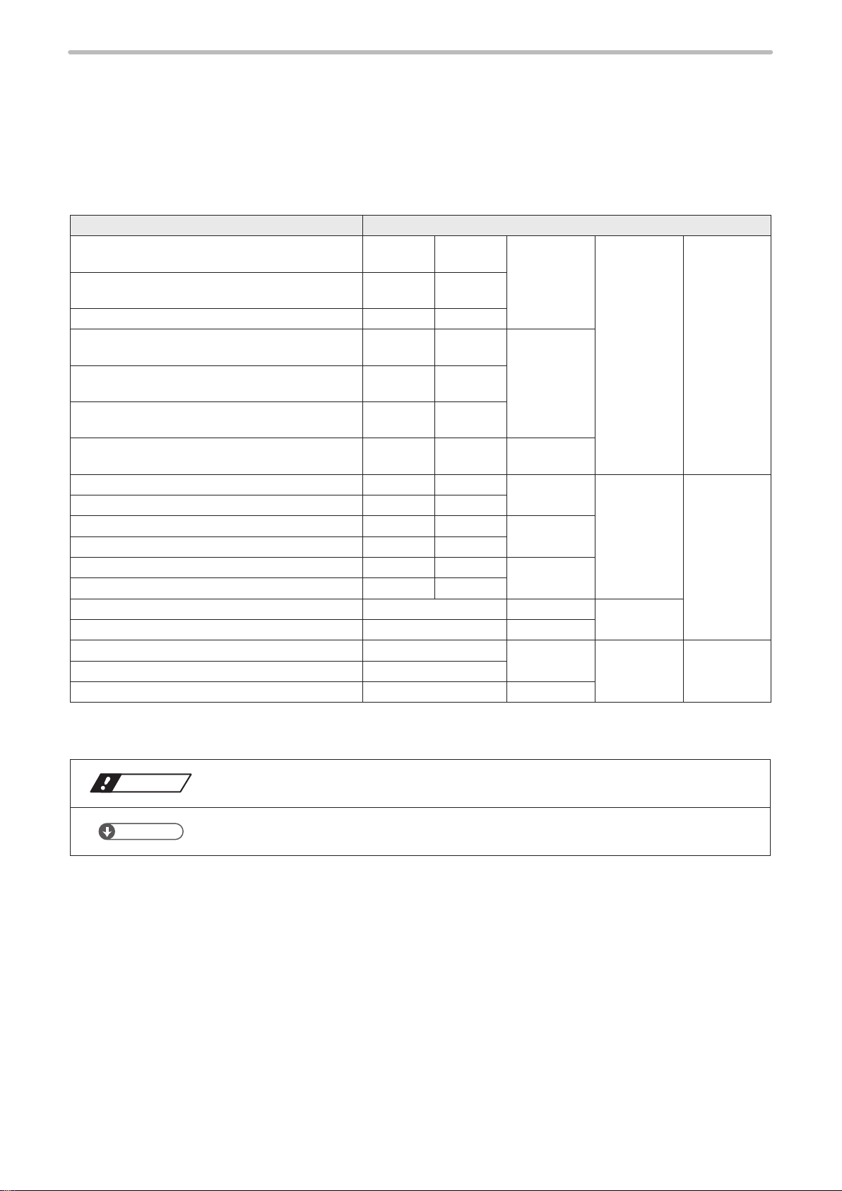
This document is subject to the following Laser Marker models.
If the setting contents or specications vary by models, the target models are specied in the text.
In the text, multiple models may be described collectively, as shown in the table below.
Note that the illustration and screen image may vary with model.
Target model Description in the text
LP-M200, LP-M200-CHN, LP-M200-S,
LP-M200-S-CHN
LP-M500, LP-M500-CHN, LP-M500-S,
LP-M500-S-CHN
LP-MA00, LP-MA00-CHN LP-MA00 LP-MAxx
LP-M205, LP-M205-CHN, LP-M205-S,
LP-M205-S-CHN
LP-M505, LP-M505-CHN, LP-M505-S,
LP-M505-S-CHN
LP-MA05, LP-MA05 -CHN, LP-MA05 -S,
LP-MA05-S-CHN
LP-MA06, LP-MA06-CHN, LP-MA06-S,
LP-MA06-S-CHN
LP-S200, LP-S200-CHN, LP-S200-SF LP-S200 LP-S2xx LP-Sxx0 LP-Sxxx
LP-S500, LP-S500-CHN, LP-S500-SF LP-S500 LP-S5xx
LP-S202, LP-S202-CHN, LP-S202-SF LP-S202 LP-S2xx LP-Sxx2
LP-S502, LP-S502-CHN, LP-S502-SF LP-S502 LP-S5xx
LP-S205, LP-S205-CHN, LP-S205-SF LP-S205 LP-S2xx LP-Sxx5
LP-S505, LP-S505-CHN, LP-S505-SF LP-S505 LP-S5xx
LP-S500W, LP-S500W-CHN LP-S500W LP-Sxx0(W) LP-SxxxW
LP-S505W, LP-S505W-CHN LP-S505W LP-Sxx5(W)
LP-Z130, LP-Z130-CHN LP-Z130 LP-Zxx0 LP-Zxxx LP-Z Series
LP-Z250, LP-Z250-CHN LP-Z250
LP-Z256, LP-Z256-CHN LP-Z256 LP-Zxx6
LP-M200 LP-M2xx LP-Mxx0 LP-Mxxx
LP-Mxxx-S
LP-M500 LP-M5xx
LP-M205 LP-M2xx LP-Mxx5
LP-M505 LP-M5xx
LP-MA05 LP-MAxx
LP-MA06 LP-MAxx LP-Mxx6
LP-Sxxx-SF
LP-M Series
LP-S Sries
LP-Sxxx(W)
Symbol indications
Notice
Reference
• “Notice” denotes any instructions or precautions for using this product. To prevent the
damage or malfunction of the product, observe these precautions fully.
• “Reference” denotes any hints for operation, detail explanations, or references.
4

Type of manuals
ME-LPMSZ-SR-9
For this product, the following manuals are prepared. Read each manuals and operate this product correctly and safely.
Save the manuals for future use.
Safety / Setup / Maintenance Guide
This manual describes the safety precautions and the items required for the introduction, installation and maintenance of
the laser marker.
• Precautions and safety measures: All users shall be required for reading this part.
• Specications and outer dimensions
• Setup and connecting method
• I/O control method (signal layout, I/O rating, timing chart etc.)
• Maintenance
• Troubleshooting
Operation Manual
This manual describes how to operate the laser marker and set the marking data using touch panel console or monitor
and mouse.
Laser Marker NAVI plus Operation Manual
This manual describes how to operate the laser marker and set the marking data using PC setting software “Laser
Marker NAVI plus”.
Serial Communication Guide
This manual describes the communication commands to control the laser marker externally using the serial
communication (RS-232C/Ethernet). It describes the communication conditions, communication data formats,
communication commands, and the control samples.
Mainly the machine builder and system integrator shall be required for reading this manual.
Reference
• PDF data of each manual are included on an attached CD-ROM “Laser Marker Utility”.
• To read the PDF manual, Adobe Reader (Version X or later) of Adobe Systems Incorporated is required.
5

Contents
ME-LPMSZ-SR-9
Preface ……………………………………………………………………………… 2
Cautions in Handling
How to Read this Document
………………………………………………………………… 2
……………………………………………………… 4
1 Before External Control …………………………………………… 8
1-1 Operation by External Devices ……………………………………………… 9
1-1-1 Operation method using external control device …………………………… 9
1-1-2 Operation procedure with external control ………………………………… 10
1-2 Before External Control ………………………………………………………… 11
1-2-1 DIP switch setting …………………………………………………………… 12
1-2-2 Communication condition setting …………………………………………… 14
1-2-3 Shift to remote mode ………………………………………………………… 15
2 Basics of Serial Communication (RS-232/Ethernet) ……………16
2-1 Preparation of Command Control ……………………………………………17
2-1-1 RS-232C ……………………………………………………………………… 17
2-1-2 Ethernet ……………………………………………………………………… 20
2-2 Command Reception Condition ………………………………………………22
2-3 Connection Check ………………………………………………………………23
2-4 Control Sample …………………………………………………………………24
2-5 Communication Data Format …………………………………………………28
2-5-1 Command data ……………………………………………………………… 28
2-5-2 Response data ……………………………………………………………… 29
2-6 Communication Sequence ……………………………………………………32
3 Communication Command and Function ……………………… 34
3-1 Command at standard mode …………………………………………………35
3-1-1 Command list ………………………………………………………………… 35
3-1-2 Command description ……………………………………………………… 39
3-2 LP-F10/F10W Mode ………………………………………………………… 116
3-2-1 Selecting DIP switch ………………………………………………………… 116
3-2-2 LP-F10/F10W mode command list ………………………………………… 117
3-2-3 Each command description in LP-F10/F10W mode ……………………… 120
6
Troubleshooting ……………………………………………………… 165
Troubleshooting …………………………………………………………………… 166
Error Indication
Alarm ………………………………………………………………………………… 178
…………………………………………………………………… 178

Warning ……………………………………………………………………………… 181
ME-LPMSZ-SR-9
Character Code Table ……………………………………………… 186
ASCII Code ………………………………………………………………………… 187
Shift-JIS Code
…………………………………………………………………… 188
Index ………………………………………………………………… 199
Index ……………………………………………………………………………… 200
7

1 Before External Control
ME-LPMSZ-SR-9
1-1 Operation by External Devices
ME-LPMSZ-SR-9
1-1-1 Operation method using external control device
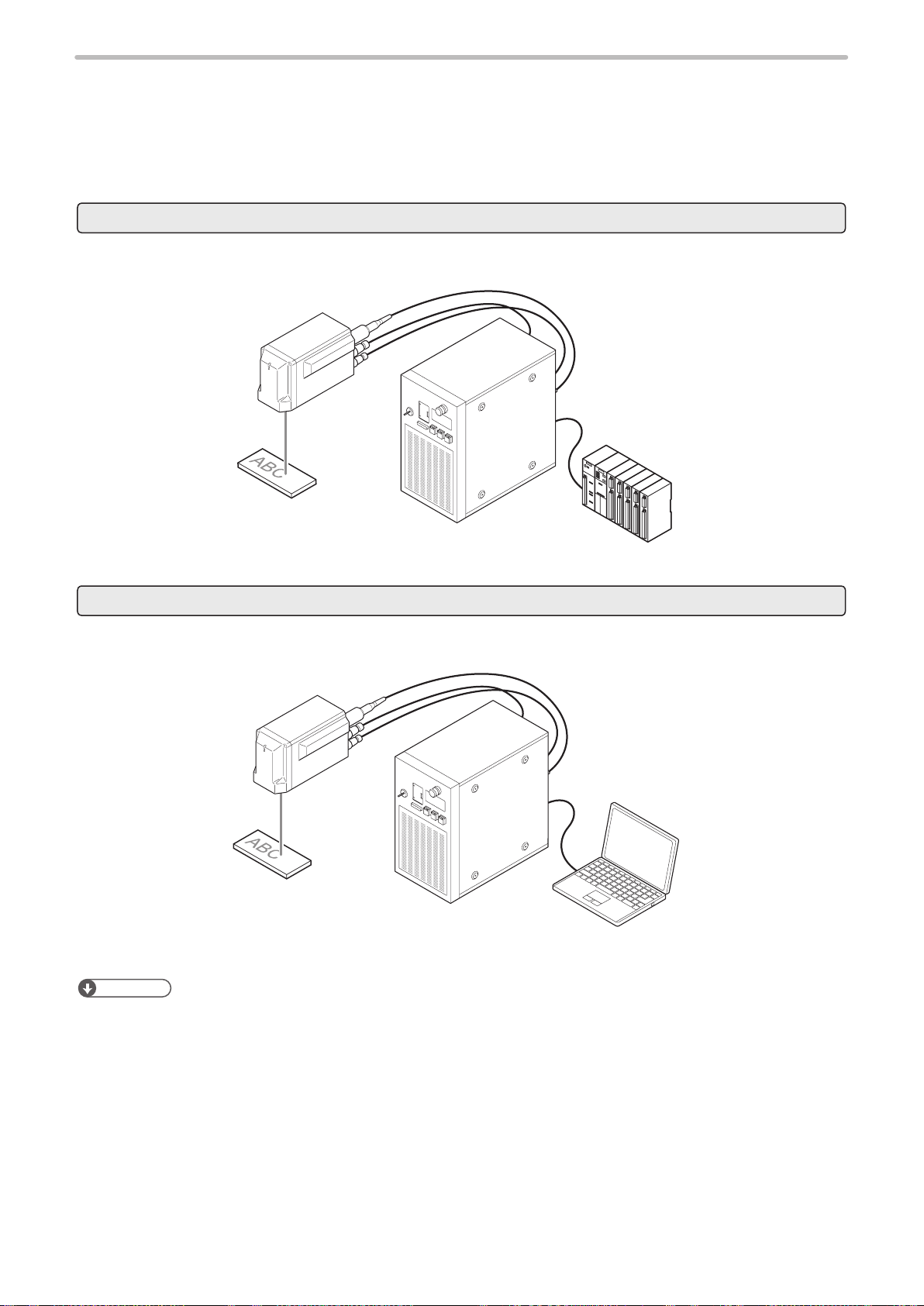
To control the laser marker with the external control device, the following connecting methods are applicable:
External control using I/O : Remote mode operation
Controls the laser marker from external devices such as PLC using various I/O signals loaded into the laser marker.
For details, refer to “Safety / Setup / Maintenance Guide”.
I/O terminal block
I/O connector
PLC, etc.
External control by serial communication commands (RS-232C/Ethernet) : Remote mode operation
Controls the laser marker from external devices such as PLC using communication commands via RS-232C or Ethernet.
For details, refer to “2 Basics of Serial Communication (RS-232/Ethernet)” (P.16).
Ethernet or
RS-232C
External control device
Reference
• It is available to combine I/O and the serial communication for external control.
• To input marking trigger with I/O and congure other settings with a screen operation manually, use Run mode. For
details, refer to “Safety / Setup / Maintenance Guide”.
9
1-1-2 Operation procedure with external control
ME-LPMSZ-SR-9
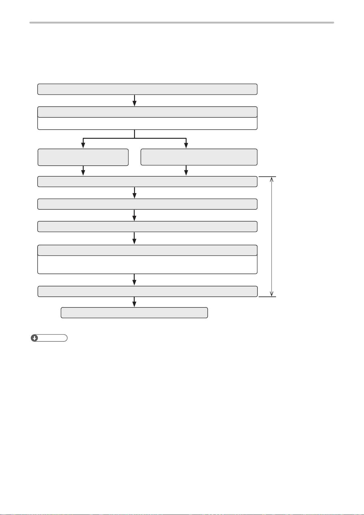
■ Operation example when controlling the laser marker from external control
devices such as PLC
Turn ON key switch of laser marker controller
Remote mode ON
Refer to “1-2-3 Shift to remote mode” (P.15).
I/O control
Select le
Laser pumping ON
Open shutter
READY output ON
The device is ready for receiving the marking starting signal (trigger).
For LP-Mxxx-S type, open the laser gate to turn ON the ready signal.
Marking trigger input ON
Marking (Laser radiation)
Control by serial communication commands
about 15 to 20 seconds
Control by using I/O
or communication
commands
10
Reference
• It is available to combine I/O and the serial communication for external control.
• Congure the environment setting in advance before using external control. Refer to “1-2 Before External Control” (P.11).
1-2 Before External Control
ME-LPMSZ-SR-9
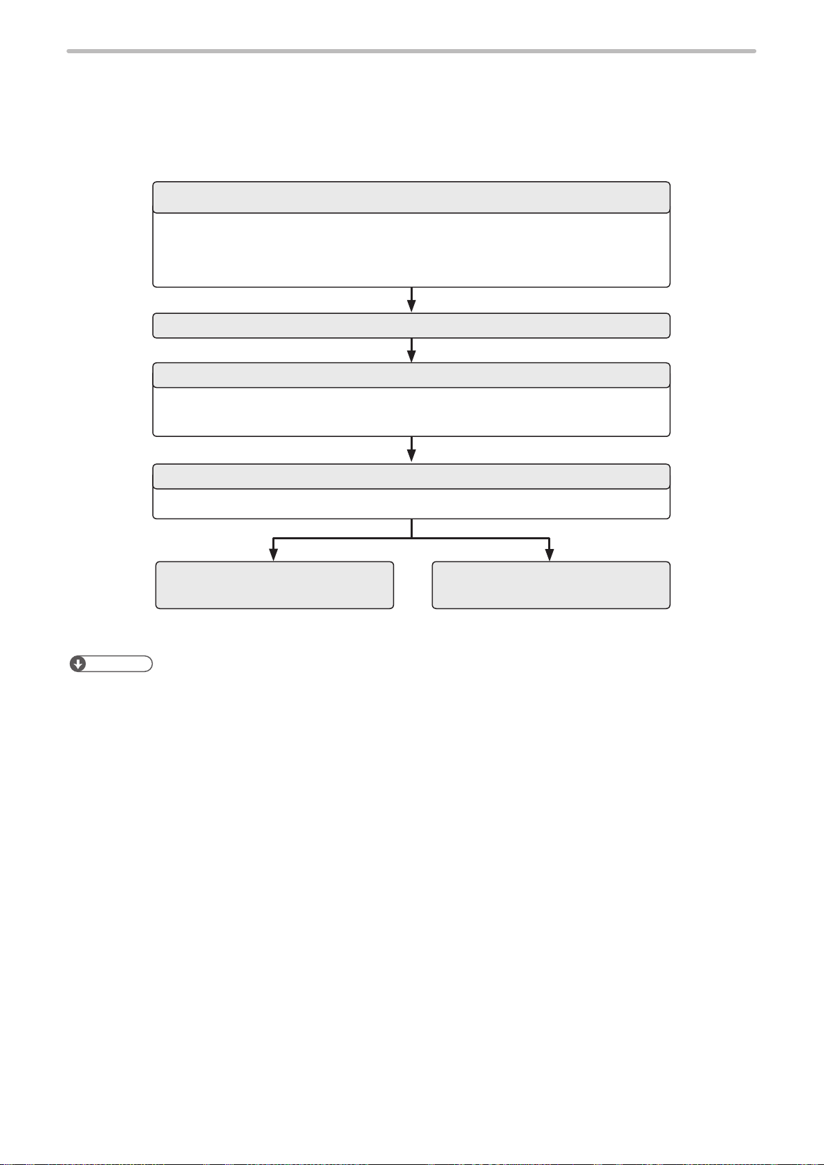
The following settings are required before the external control by using I/O or communication commands.
■ Setting ow to start external control
DIP switch setting
• DIP switch No. 2: Select control method, I/O or command for some specic operations.
• DIP switch No. 5 and No. 6: Select setting method of remote mode.
• DIP switch No. 7 and No. 8: Select compatible mode for the previous models.
Refer to “1-2-1 DIP switch setting” (P.12).
Turn ON laser marker
Communication environment setting
Set I/O and communication conditions in the environment setting screen.
Refer to “1-2-2 Communication condition setting” (P.14).
Remote mode ON
Refer to “1-2-3 Shift to remote mode” (P.15).
I/O control
Reference
• For the installation and the setup of the laser marker, refer to “Safety / Setup / Maintenance Guide”.
Control by serial communication
commands
11

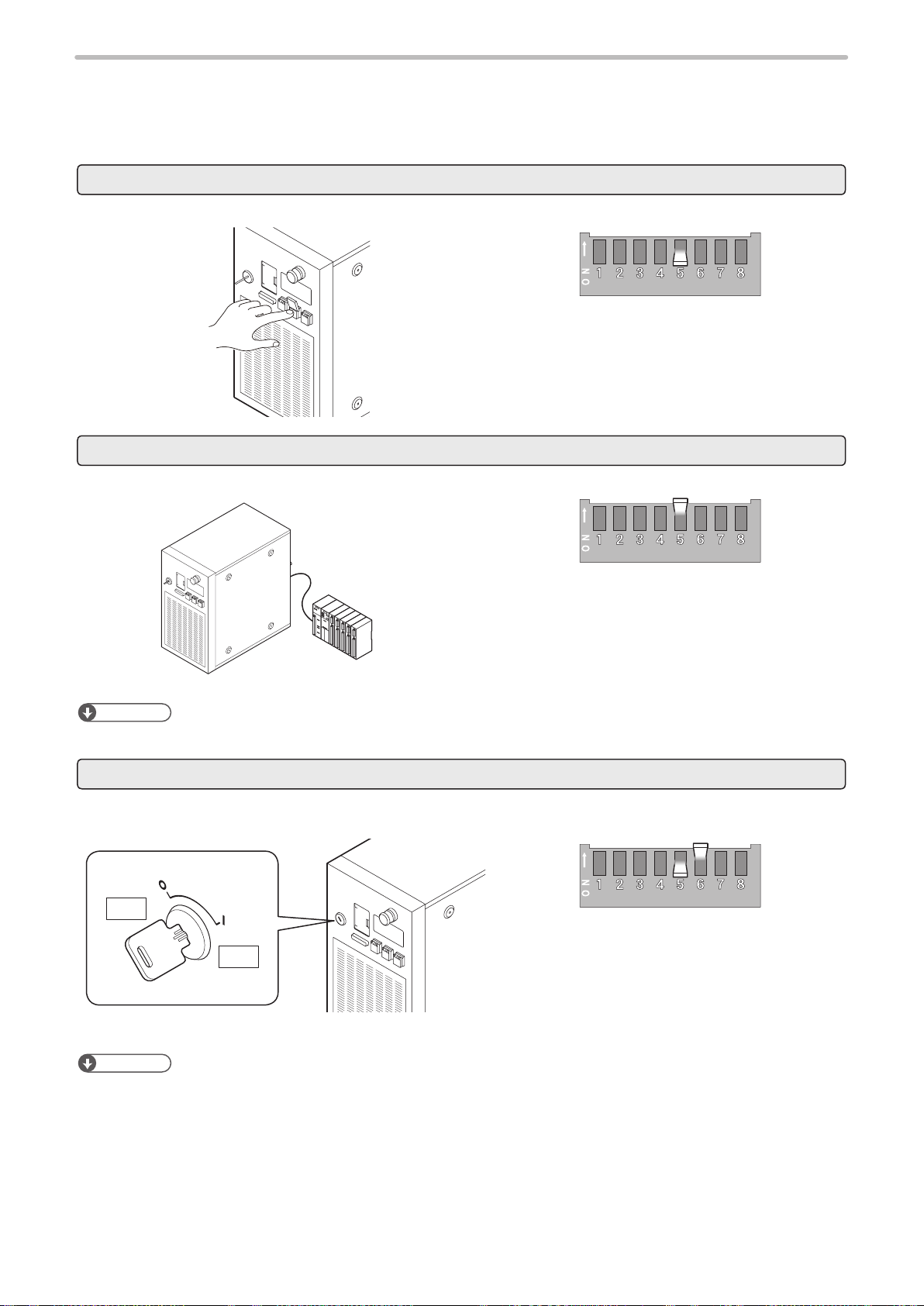
1-2-1 DIP switch setting
ME-LPMSZ-SR-9
Set the operational options for the external control with the DIP switch equipped on the controller rear side.
Reference
• The initial setting of all DIP switches is OFF.
• Turn OFF the power at DIP switch setting.
• For the details on DIP switch, refer to “Safety / Setup / Maintenance Guide”.
Turn OFF the power of laser marker.
1.
Remove the DIP switch cover on the rear of the controller.
2.
ON
OFF
DIP switch
Rear of controller
With DIP switch No. 2, select the control method, I/O or command
3.
for some specic operations.
DIP switch No. 2 Control method for specic operations
ON Control by serial communication commands for the
following operations
• Laser pumping (LSR)
• Shutter control (SHT)
• Guide laser (GID)
• Laser check radiation (SPT)
• Laser power measurement (PWM)
• Power check (PWR)
• Test marking (TST)
OFF (initial setting) Control by I/O for the following operations
• Laser pumping
• Shutter control
• Guide laser
Reference
• “Laser check radiation”, “Laser power measurement”, “Power check” and “Test marking” cannot be controlled by I/O.
They can be controlled only by using serial communication in the remote mode.
12

With DIP switch No. 5, select the setting method of the remote
CAUTION
ME-LPMSZ-SR-9
4.
mode.
DIP switch No. 5 Setting method of remote mode
ON Use the input signal of REMOTE IN (X5) on I/O terminal.
OFF(initial setting) Use the remote switch on the front of the controller.
Reference
• When DIP switch No. 5 is ON, the remote switch on the controller is not available.
When DIP switch No. 5 is OFF, select the remote mode state at
5.
powered ON with DIP switch No. 6.
DIP switch No. 6 Remote mode state at powered ON
ON Starts up with remote mode ON
OFF (initial setting) Starts up with remote mode OFF
Reference
• When DIP switch No. 5 is ON, keep DIP switch No. 6 OFF.
• When DIP switch No. 6 is ON, “X5: REMOTE IN” signal on I/O terminal is not available.
• If the DIP switch No. 5 or No. 6 are used while turned on, construct a system
for re-pumping the laser manually as safety protection measures after the stop
of the laser radiation due to an emergency stop or an interlock.
If you want to use the command format compatible with the former models of LP-F10/LP-F10W
6.
series, select the command mode using DIP switch No. 7 and No. 8.
Standard Mode LP-F10 Mode LP-F10W Mode
No. 7: OFF
No. 8: OFF
Notice
• Even with the use of LP-F10/F10W mode, there is a difference in communication processing time and I/O operation
timing between older model of LP-F10/LP-F10W and LP-M/LP-S/LP-Z series.
Install the DIP switch cover to the controller.
7.
Notice
• A plastic cover is installed on the DIP switch. Install this cover always to avoid the dust penetration to the controller.
Turn ON the power of laser marker.
8.
No. 7: ON
No. 8: OFF
No. 7: OFF
No. 8: ON
13
1-2-2 Communication condition setting
ME-LPMSZ-SR-9
To control the laser marker by using I/O or communication commands, congure the following items in advance on the
environment setting screen.
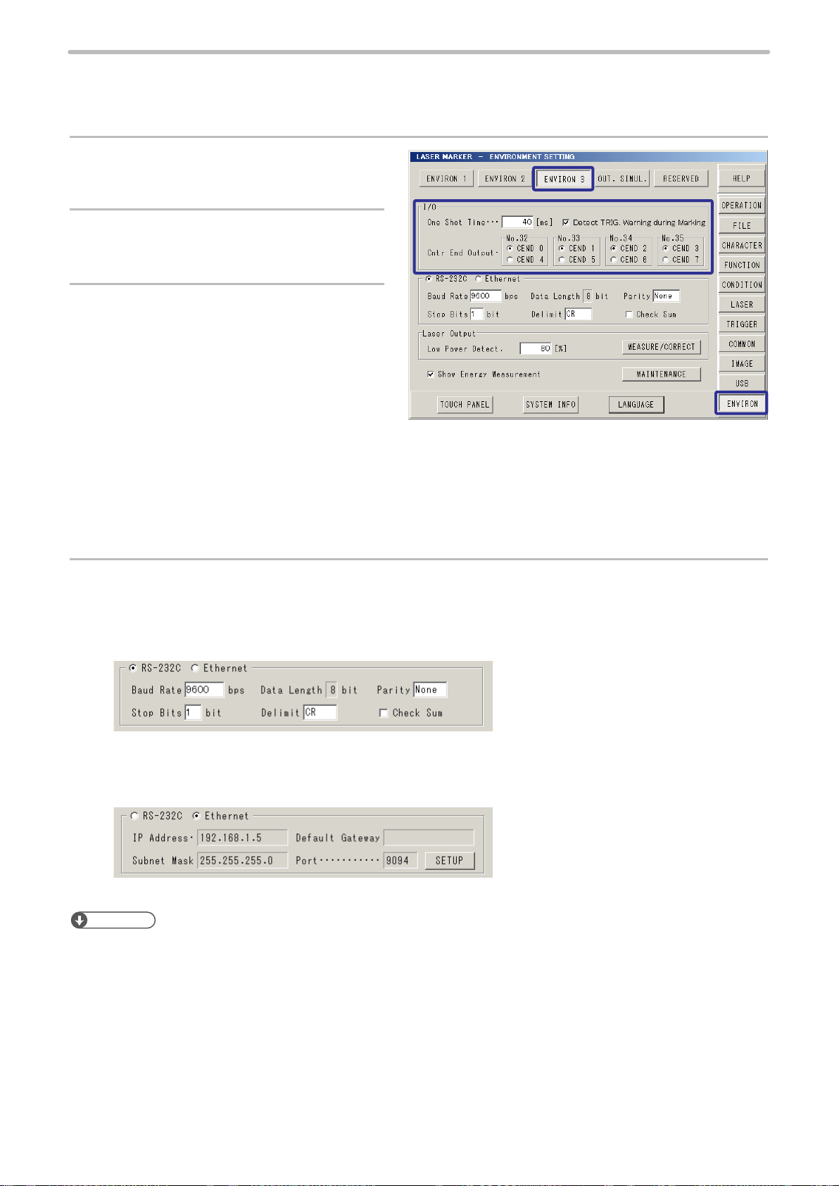
Select “ENVIRON” on the right menu.
1.
Select “ENVIRON 3”.
2.
To use I/O signals, congure the following
3.
output conditions:
• One-shot time:
Sets the output duration for some signals such
as MARK END OUT and SET OK OUT.
Setting range: 2 ms to 510 ms (initial value is 40
ms)
• Detect TRIG. Warning during Marking
Congure if you will output (ON) or will not output (OFF) the warning for the invalid trigger. With enabling this setting,
the warning is output when the marking trigger that cannot be accepted was input while the shutter is opened.
• Counter end output
Assign the counter No. from 0 to 7 to the counter end output signals in I/O connector pin No. 32 to 35 respectively.
To use the serial communication commands, set communication conditions for Ethernet or RS-
4.
232C.
• For RS-232C:
Congure the communication conditions of the laser marker corresponding to the external control device.
Default settings are as follows:
• Baud Rate: 9600 bps
• Parity: None
• Stop Bits: 1 bit
• Delimit: CR
• Check sum: None
• For Ethernet:
Congure the communication conditions according to the network environment.
Default settings are as follows:
• IP Address: 192.168.1.5
• Subnet Mask: 255.255.255.0
• Default Gateway: None
• Port: 9094
14
Reference
• The laser marker can be controlled by I/O and communication commands combined.
• RS-232C and Ethernet cannot be used at the same time.
• The parameters on the environment setting screen are applied to the laser marker directly without saving.
• When using RS-232C, specify the “Flow control” to “None” at the communication port settings of the external control
device.
1-2-3 Shift to remote mode
ME-LPMSZ-SR-9
To control the laser marker externally using I/O or serial communication commands, set the operation mode to the remote
mode in one of the following methods.
Select the method to switch to the remote mode by setting the DIP switch on the rear side of the controller.
Use the remote switch on the front of the controller.
Turn ON the remote mode switch on the front of the controller.
Turn OFF the DIP switch No. 5.
Refer to “1-2-1 DIP switch setting” (P.12).
Use input signal of X5 “REMOTE IN” on I/O terminal.
Turn ON the remote mode input (X5) of the I/O terminal on the rear of the controller.
X5: REMOTE IN
Turn ON the DIP switch No. 5.
Refer to “1-2-1 DIP switch setting” (P.12).
Reference
• When DIP switch No. 5 is ON, the remote switch on the controller is not available.
Start the laser marker in the remote mode
The laser marker starts up always in the remote mode state. Use the remote mode switch button of the controller for
releasing and resetting the remote mode.
ヱヰヸユン
OFF
ON
Turn OFF the DIP switch No. 5 and turn ON the DIP
switch No. 6.
Refer to “1-2-1 DIP switch setting” (P.12).
Reference
• When DIP switch No. 6 is ON, “X5: REMOTE IN” signal on I/O terminal is not available.
• The remote switch on the controller is available when DIP switch No. 6 is ON.
15

2 Basics of Serial Communication
ME-LPMSZ-SR-9
(RS-232/Ethernet)
2-1 Preparation of Command Control
ME-LPMSZ-SR-9
This product has RS-232C port and Ethernet port as the serial communication interfaces on the rear side of the controller.
Before using serial communication control, congure the DIP switch and the environment settings. Refer to “1-2 Before
External Control” (P.11).
Reference
• For communication with external devices, select either RS-232C or Ethernet port. (They cannot be used at the same
time, or switched.) The port selected in the environment setting screen indicates the valid communication port. For
details of the environment setting screen, please refer to the Operation Manual.
• If Ethernet is not used for the external control, connect nothing to the Ethernet port.
■ Combined control by serial communication and I/O
• The control method for “Laser Control”, “Shutter Control”, and “Guide Laser Control” should be selected from either the
serial communication or I/O. Turn the No. 2 DIP switch on the back surface of controller before turning on the power to
select the control (serial communication or I/O).
• Those commands can be used only when the DIP switch No. 2 is set to ON:
Laser pumping (LSR), Shutter (SHT), Guide LD indication (GID), Laser check radiation (SPT), Test marking (TST), Laser
power measurement (PWM), Power check (PWR)
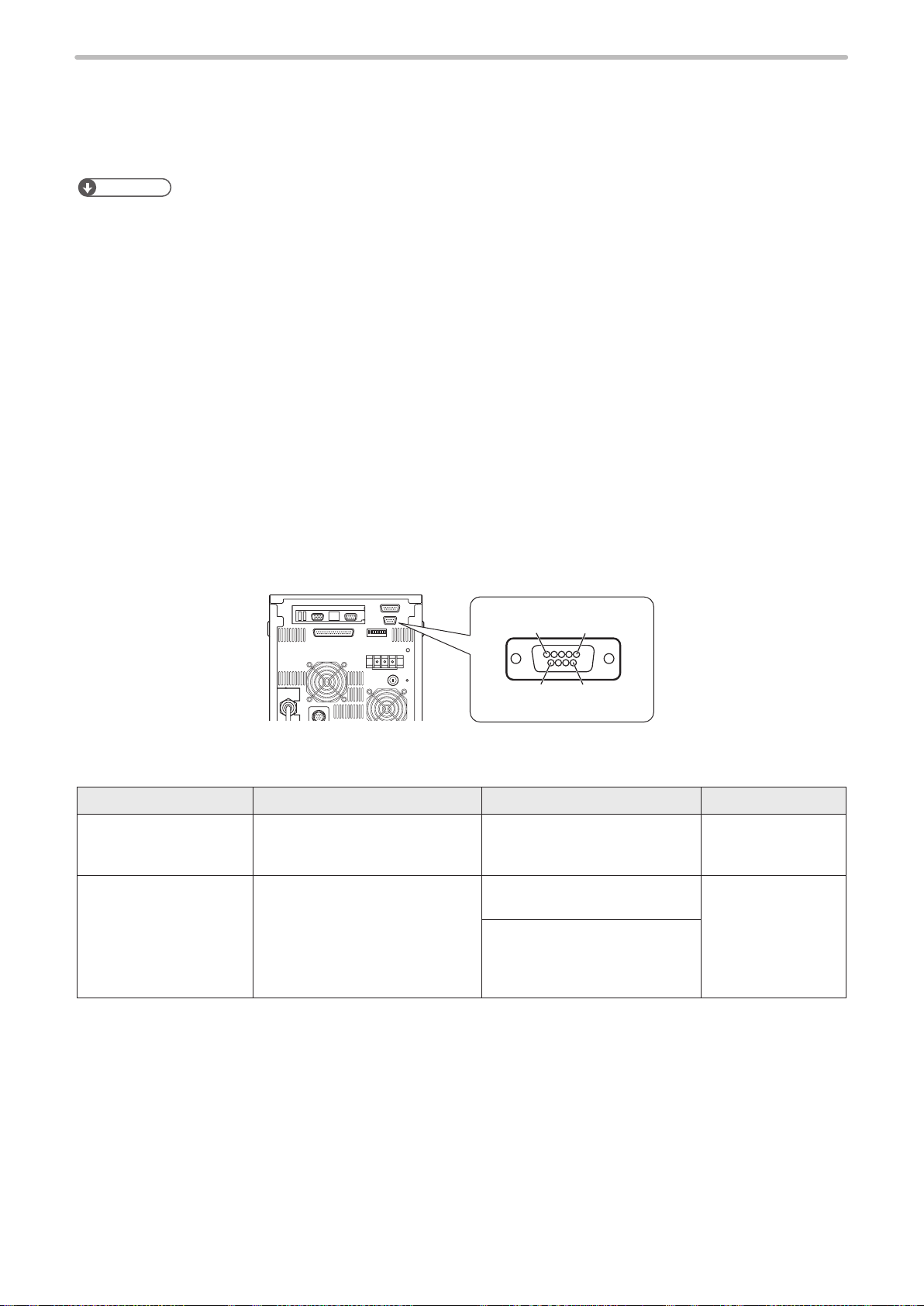
2-1-1 RS-232C
■ Interface specications and connection
To control laser marker by communication command with RS-232C, connect the RS-232C port on the rear of the controller
to the external control device.
51
6
Rear of controller
Connector position Connector specications Model Manufacturer name
On the laser marker side D-sub 9-pin, male
Screw type: No. 4-40UNC inch
screw, female
User side D-sub 9 -pin, female
Screw type: No. 4-40UNC inch
screw, male
Laser marker controller side
RS-232C por t (male)
- -
Recommended connector
17JE-13090-02(D1)A
Recommended connector cover
17JE-09H-1C4-CF
or
17JE-09H-1C-CF
9
DDK Ltd.
17

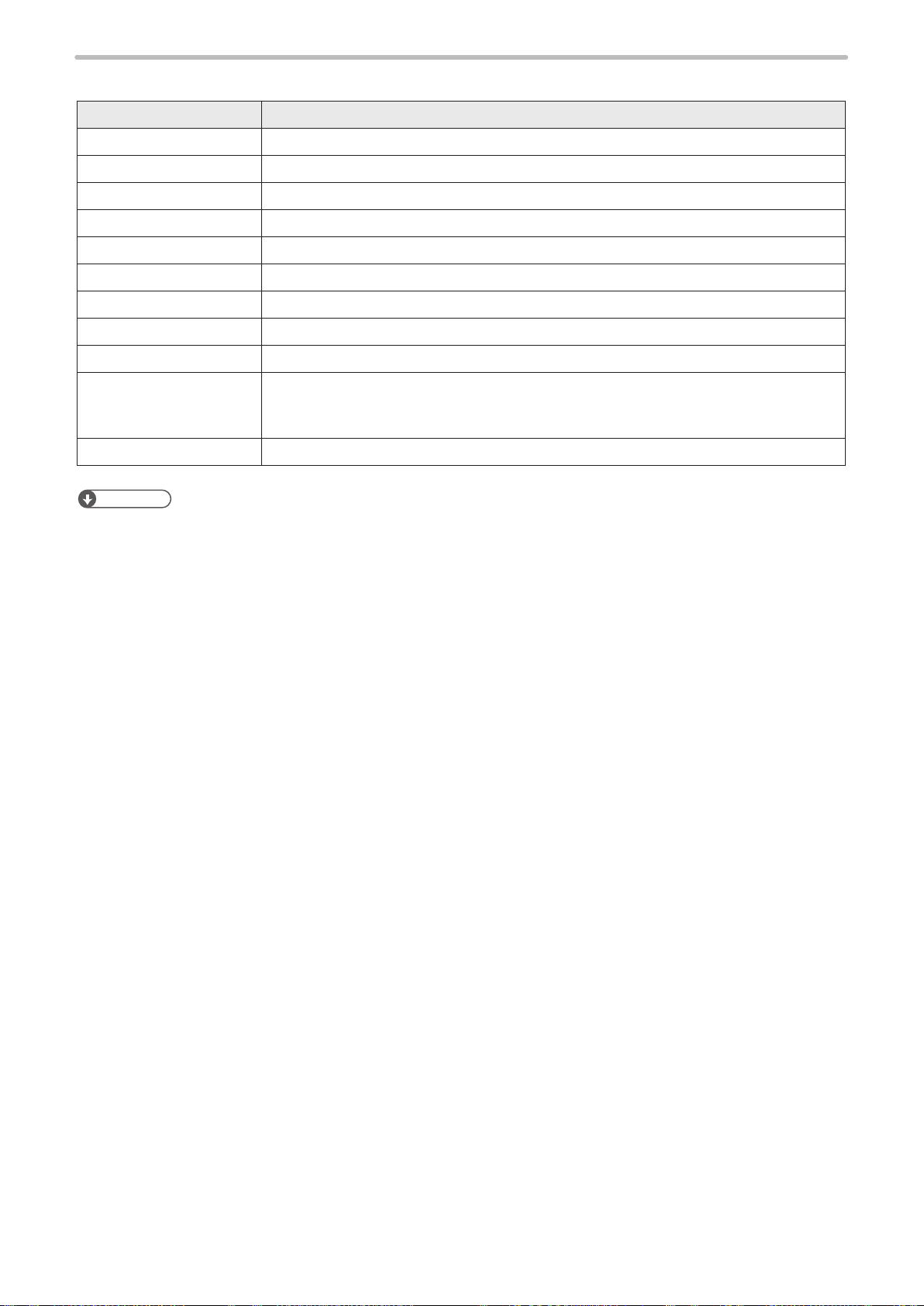
■ Signals of RS-232C connector
ME-LPMSZ-SR-9
Terminal No. Signal Function
1 Reserve Do not use this terminal.
2 RxD (RD) Receiving data: Connect TxD (SD) of the external control device.
3 TxD (SD) Transmission data: Connect RxD (RD) of the external control device.
4 Reserve Do not use this terminal.
5 GND (SG) Signal ground: Connect GND (SG) of the external control device.
6 Reserve Do not use this terminal.
7
8
9
■ Connecting to external control devices
• To connect the laser marker to the PC for control, use a commercially available RS-232C cross cable (9-pin).
• In case of connecting to PLC, a type of the cable (straight or cross) differs depending on a manufacturer or a model.
Please follow the PLC manual.
• To connect RS-232C terminal without using a commercially available RS-232C cable, connect only 3 signals of RxD,
TxD and GND and do not use other signals on the laser marker side.
• The external controller may need a signal line connection (loop back line) other than RxD, TxD, or GND on the external
control device side depending on the specications of the external control device. Read the instruction manual of the
external control device and connect it to the laser marker appropriately.
Connection example
RS-232C connector
(Laser marker)
Terminal No.
2
3
5
Signal
RxD
TxD
GND
Cross cable
*
* The loop back wiring on the external control device side shown in the above gure is just an example. The wiring
method varies depending on the specications of each external control device. Read the instruction manual of the
external control device and connect it to the laser marker appropriately.
External controller
RxD
TxD
DTR
RTS
CTS
Terminal No.
2
3
5
1
4
6
7
8
Signal
GND
DCD
DSR
18
■ RS-232C communication conditions
ME-LPMSZ-SR-9
Item RS-232C communication conditions
Synchro system Start-stop method
Communication Full-duplex transmission
Baud Rate 1200 / 2400 / 4800 / 9600 / 19200 / 38400 bps (initial setting: 9600 bps)
Data length 8-bit xed
Parity None / Even / Odd (initial setting: None)
Stop Bits 1-bit / 2-bit (initial setting: 1-bit)
Flow control None
Check sum OFF / ON (initial setting: OFF)
Delimiter CR / CR + LF (initial setting: CR)
Start Code
Reception timer Timeout monitoring ON (10 sec.)
Reference
• For the details of the setting method of communication conditions, refer to “1-2-2 Communication condition setting” (P.14).
• Setting request, Reading request, Reading response: STX
• Normal response: ACK
• Abnormal response: NAK
19
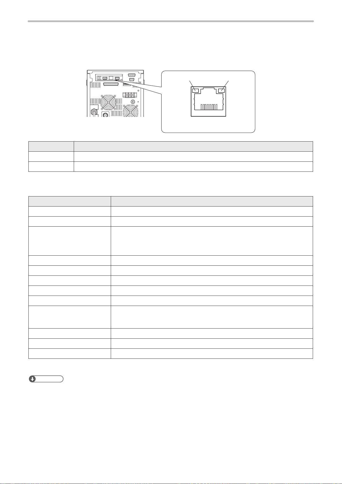
2-1-2 Ethernet
ME-LPMSZ-SR-9
■ Port specications
When Ethernet perform communication control of the laser marker, use an Ethernet port.
Green LED
Rear of controller
Light color Description
Green Lights up while 1000 BASE-T Management port is in link-up state.
Orange Blinks while there is activity on this port.
RJ-45 8-pole connector
Orange LED
■ Ethernet communication conditions
Item Ethernet communication conditions
Communication protocol TCP/IP
Standards IEEE802.3ab (1000BASE-T) / IEEE802.3u (100BASE-TX) / IEEE802.3 (10BASE-T)
Applicable cable Category 5e or higher
• To connect an external device and one laser marker: Cross cable
• To connect an external device and two or more laser markers through a HUB or a
router: Straight cable
Applicable HUB (or rooter) 1000BASE-T / 100BASE-TX / 10BASE-T compatible
IP Address 1.0.0.0 to 223.255.255.255 *1 / Initial value : 192.168.1.5
Subnet Mask 128.0.0.0 to 255.255.255.254 / Initial value : 255.255.255.0
Default Gateway 1.0.0.0 to 223.255.255.255 *1 / Initial value : Unspecied (0.0.0.0)
Port 5001 to 65534, except 9090 and 9091 / Initial value: 9094
Start Code
Check sum OFF
Delimiter CR xed
Reception timer Timeout monitoring ON (10 sec.)
*1 : Do not use “127” in the rst octet.
Reference
• Although the cable length between the devices is specied as 100 m at maximum in the Ethernet standard, use of cable
length below 10 m is recommended to avoid communication failure caused by noise and device malfunction.
• The communication control of the laser marker through the Ethernet should be performed in a secure network
environment.
• Depending on the combination, there are cases where IP Address and Subnet Mask values cannot be set even if they
are within the setting range.
• Make sure that the IP address for the laser marker on the network is not overlapping the IP address for the PC.
• If Ethernet is not used for the external control, connect nothing to the Ethernet port.
• For the details of the setting method of communication conditions, refer to “1-2-2 Communication condition setting” (P.14).
• Setting request, Reading request, Reading response: STX
• Normal response: ACK
• Abnormal response: NAK
20
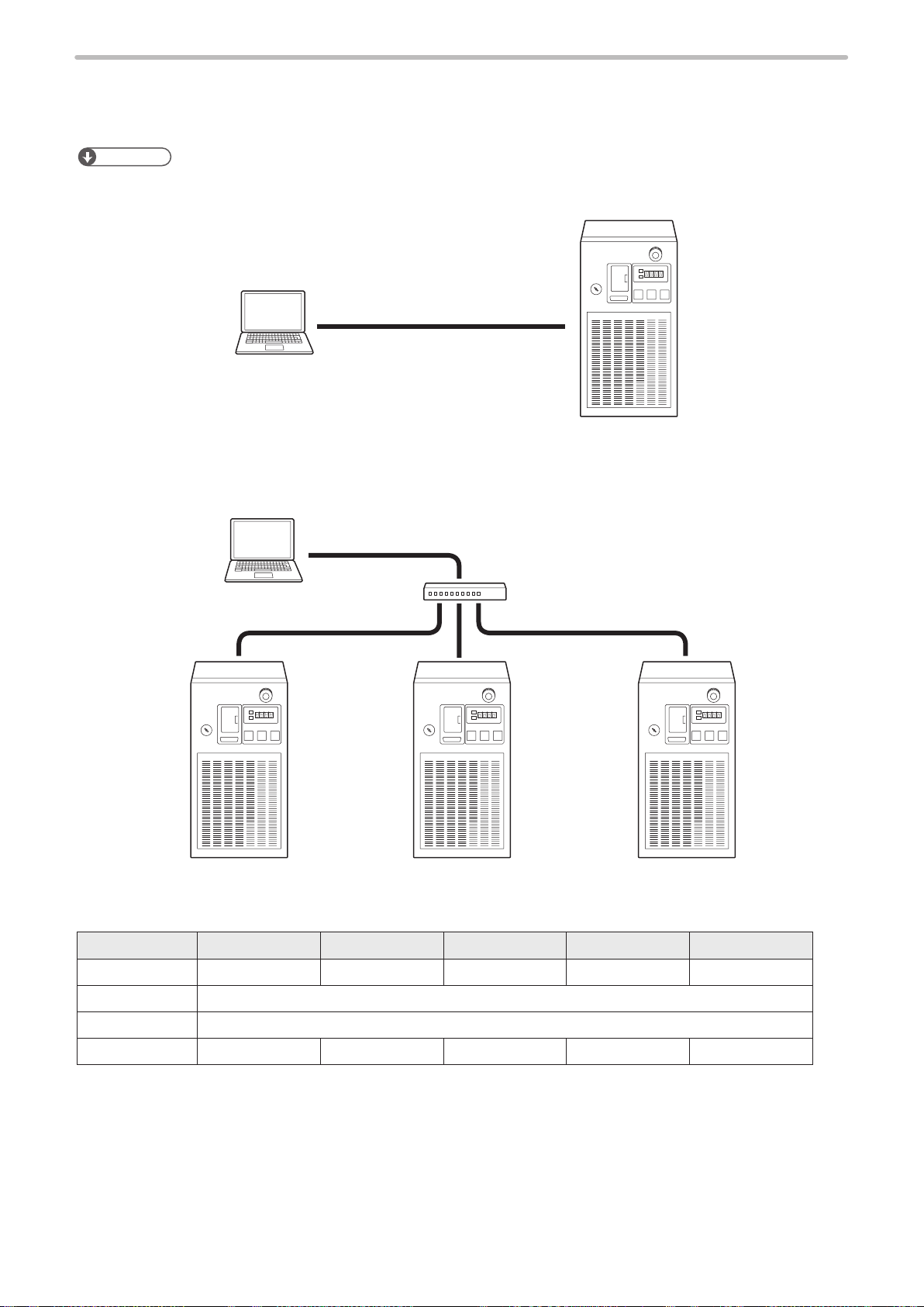
■ Connecting to external control devices
ME-LPMSZ-SR-9
• To connect an external device and the laser marker directly one to one:
Use a Category 5e or higher cross cable for connection.
Reference
• If the external control device has the AutoMDI/MDI-X function, either a straight cable or a crossed cable can be
connected to the laser marker.
Cross cable
External control device
(PC, etc.)
Laser marker controller
• To connect an external device and the laser marker one to many through a HUB or a router:
Use a HUB (or a router) that supports 1000BASE-T/100BASE-TX/10BASE-T and Category 5e or higher straight cables
for connection.
External control device
(PC, etc.)
Straight cable
Laser marker controllers
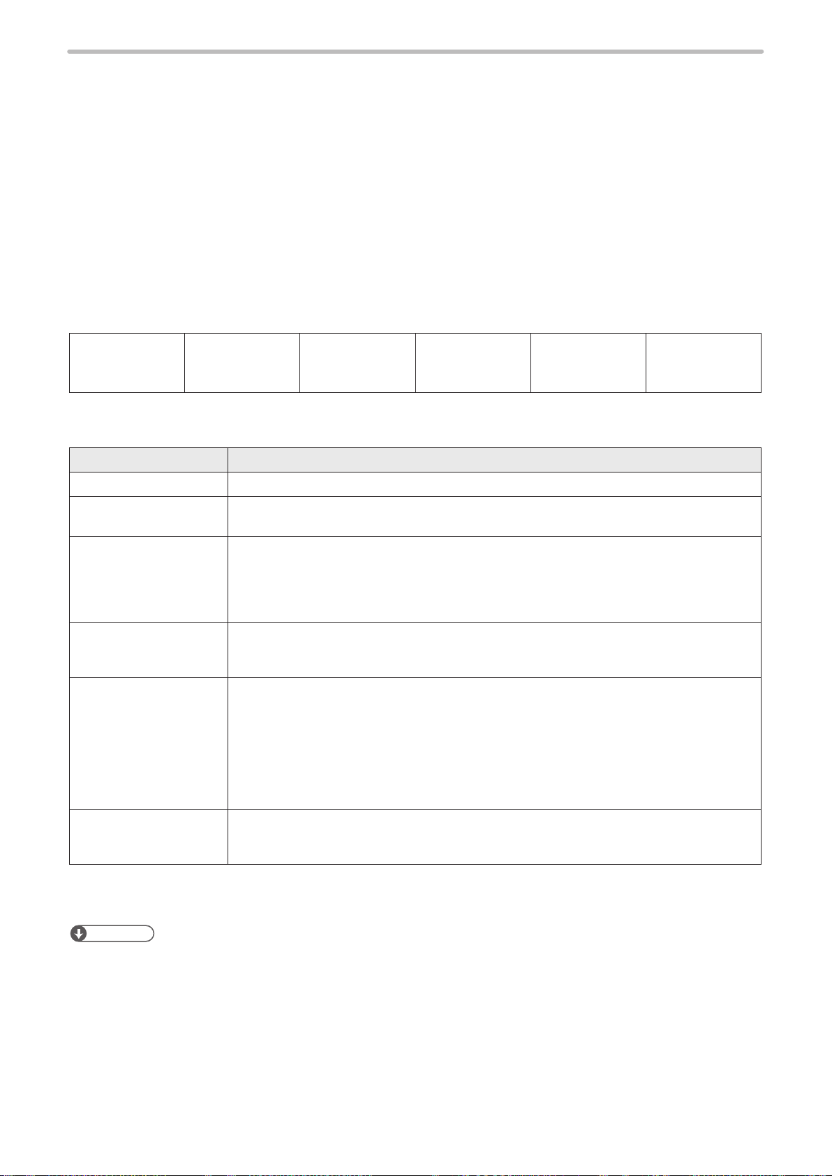
Example of communication environment setting:
Make sure that the IP address for the laser marker on the network is not overlapping the IP address for the PC.
PC Laser Marker A Laser Marker B Laser Marker C Laser Marker D
IP Address
Subnet Mask
Default Gateway
Port
192.168.1.10 192.168.1.5 192.168.1.6 192.168.1.7 192.168.1.8
255.255.255.0
- 9094 9094 9094 9094
HUB (or router)
None
21

2-2 Command Reception Condition
ME-LPMSZ-SR-9
■ Command reception permission
When transmitting the communication command including an action to update the laser marker data, commands are
refused in the marking ready ON status or the shutter open. If “reception mode ON” is set for “command reception
permission (MKM command)” before transmitting a command, marking ready is set to OFF and commands get acceptable.
Set “reception mode OFF” for “command reception permission (MKM command)” to set marking ready ON before marking.
Reference
• Commands are acceptable by closing the shutter instead of “command reception permission (MKM command)”.
However, it is recommended to use the “command reception permission (MKM command)” when the number of open
and close of the shutter is a lot.
• The command reception permission (MKM command) does not include actual opening/closing operation of the shutter.
■ Commands acceptable only with shutter closed
(Unacceptable commands when “reception mode ON” is set for command reception permission (MKM command))
• Laser power measurement (PWM)
• Power check (PWR)
• Test marking (TST)
■ Commands that do not need the command reception permission (MKM command)
The following commands can be transmitted while the shutter is opened.
(There is no need to set “reception mode ON” for “command reception permission (MKM command)”.
• File change (specied with a number) (FNO)
• File change (specied with a comment) (FNN)
• Shutter (close only) (SHT)
• Command reception permission (MKM)
• Laser pumping (LSR)
• Counter reset (CTR)
• Status request (STS)
• Marking trigger (MRK)
• Serial offset (SEO)
• Serial data input (SIN)
• Error code (ECR)
■ Commands acceptable during warning/alarm occurrence
The laser marker accepts only the following commands while an alarm or warning occurs.
Alarm
• Status request (STS)
• Error code (ECR)
Warning
• Status request (STS)
• Error code (ECR)
• Shutter (close only) (SHT)
• Command reception permission (MKM) (reception mode ON and reception mode readout)
Reference
• The laser marker should be in the remote status when controlling it by serial communication.
• The Shutter (SHT) command is not acceptable when the No. 2 DIP switch on the back surface of controller is turned to
OFF.
• To release the warning (except error codes E800 to E811) by serial communication control, close the internal shutter
by Shutter (SHT) command or set the “command reception mode ON” by Command reception permission (MKM)
command, and remove the cause of warning.
• An alarm can not be released by serial communication control.
22
2-3 Connection Check
ME-LPMSZ-SR-9
Check the connection between laser marker and external control device if they are correctly connected.
1. Turn ON the power of the external control device
2. Turn ON the key switch of laser marker.
3. Coordinate the communication conditions between laser marker and external control device
Refer to “1-2-2 Communication condition setting” (P.14).
4. Set the laser marker to the remote mode
Refer to “1-2-3 Shift to remote mode” (P.15).
5. Change the le number of the laser marker (transmit the FNO command)
Start code
STX
02 46 4E 4F 53 32 30 34 37 30 35 0D (HEX)
The transmission data above is just a sample. Check sum ON/OFF and delimiter content vary depending on the
communication environment settings.
*1 : For the command above, calculate the check sum value as follows:
Convert the data from the start code to those before the check sum into the hexadecimal values according to the
ASCII code table and add them all together. Check sum is the value calculated by converting the lower two digits of
the total value into two characters in the ASCII code.
• 02(HEX) + 46(HEX) + 4E(HEX) + 4F(HEX) + 53(HEX) + 32(HEX) + 30(HEX) + 34(HEX) + 37(HEX) = 205(HEX)
• 30 35 (HEX) is the value converted the lower two digits character (lower one-byte) 05 (HEX) into two characters
in the ASCII code
6. Check the response from the laser marker
When the connection and communication condition settings are appropriate, the laser marker returns response data.
Example of response data for normal communication
Start code
ACK
06 30 30 36 36 0D (HEX)
Example of response data for abnormal communication
Command
“FNO”
“00” Check sum Delimiter
Sub command
“S”
Data:
File No.
“2047”
Check sum*1
Delimiter
CR
Start code
NAK
15 30 36 37 42 0D (HEX)
Reference
• To use Ethernet, the delimiter is [CR] xed. To use RS-232C, select either [CR] or [CR] [LF].
• Check sum cannot be added with Ethernet communication.
“06” Check sum Delimiter
23
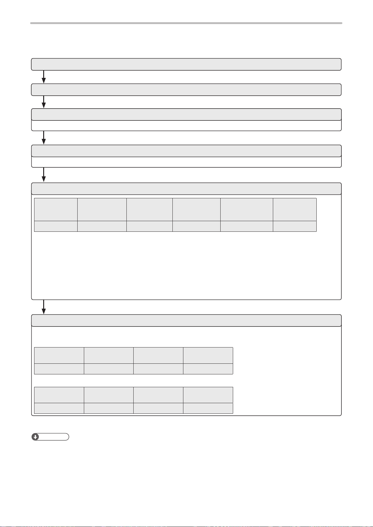
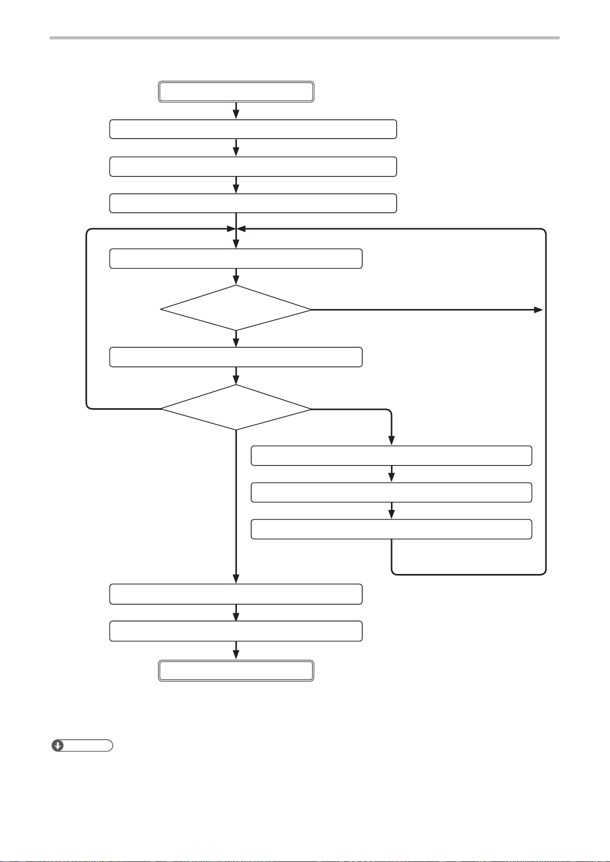
2-4 Control Sample
ME-LPMSZ-SR-9
This paragraph gives the sample of ow chart for control of laser marker by serial communication.
Remote mode ON
1. Laser pumping (ON) LSR command
2. Marking character string setting
3. General condition setting ALC command
4. Character condition setting STC command
5. Laser power setting LPW command
6. Scan speed setting SSP command
7. Shutter (open) setting SHT command
8. Status request STS command
“READY”: ON
Yes
MCS command or STR command
Send STS command
No.
again after a while.
The interval between “1
Laser pumping ON” and
“9 Marking trigger” should
be about 20 seconds or
more with the LP-Mxxx /
LP-Sxxx / LP-Zxxx type,
and about 15 seconds or
more with the LP-SxxxW
type.
9. Marking trigger MRM command
Change setting contents
To nish the marking
13. Shutter setting (close) SHT command
14. Laser pumping (OFF) LSR command
Remote mode OFF
Reference
10.
Command reception mode ON
11. Various conditions setting LSR command
12.
Command reception mode OFF
To change the settings
MKM command
MRK command
When “10. Command reception
mode ON” is transmitted, the
commands unacceptable during
shutter open become settable
and various conditions can be set.
After setting various conditions,
set marking ready ON by “12.
Command reception mode OFF”.
24
• For LP-Mxxx-S type, open the laser gate to turn ON the ready signal.
Laser gate can be controlled with any timing regardless of the command sequence by the external signal input.
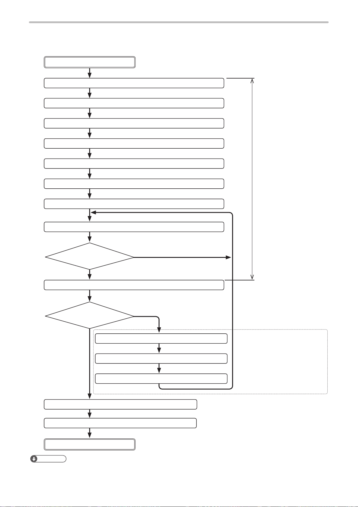
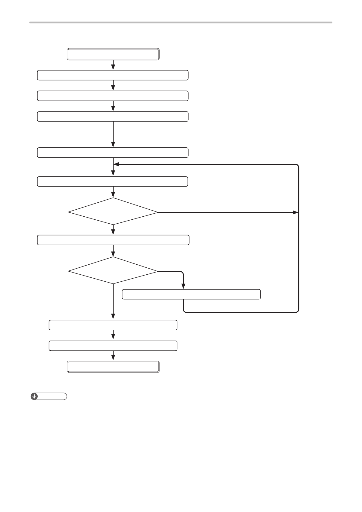
■ Control sample 1-1 : Changing the marking characters
ME-LPMSZ-SR-9
Remote mode ON
1. Laser pumping (ON) LSR command
2. Marking character string setting MCS command or STR command
3. Shutter setting (open)
4. Status request STS command
5. Marking trigger
Mark the same
character.
SHT command
“READY”: ON
Yes
MRK command
Change the character
to be marked
To nish the
marking
6. Command reception mode ON
Send the character
to be marked.
No.
Send STS command
again after a while.
Change the character.
MKM command
7. Marking character string setting MCS command or STR command
8. Command reception mode OFF
9. Shutter setting (close) SHT command
10. Laser pumping (OFF) LSR command
Remote mode OFF
Reference
• Other than STR and MCS command, SIN command can be used for changing character of marking command. SIN
command is recommended to use in case faster processing is required.
• For LP-Mxxx-S type, open the laser gate to turn ON the ready signal.
Laser gate can be controlled with any timing regardless of the command sequence by the external signal input.
MKM command
* To memorize the last marked
character into the laser marker,
save it with “File Overwriting
Registration (FOR)”.
25
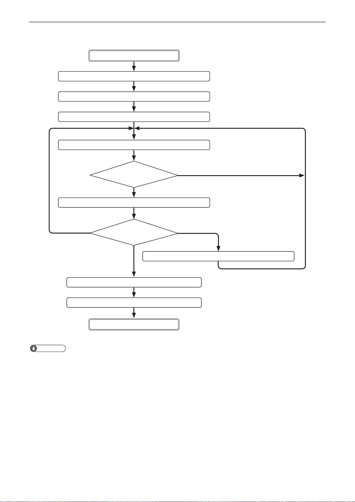
■ Control sample 1-2: Changing the marking characters for each marking
ME-LPMSZ-SR-9
Remote mode ON
1. Laser pumping (ON) LSR command
2. Select le No. FNO command
3. Shutter setting (open) SHT command
* Before sending SIN data, keep 20 sec. (LP-Mxxx / LP-Sxxx / LP-Zxxx) or 15 sec. (LP-SxxxW)
after turning ON the laser pumping, and 1 sec. after the opening shutter.
4. Serial data input SIN command
5. Status request STS command
“READY”: ON
* “READY” will turn ON after the SIN command reception.
Yes
6. Marking trigger MRK command
Change the character.
“READY”: OFF
No.
Select the le set “Command (SIN)
specied character”
Send the character data to be marked.
Send STS command
again after a while.
To nish the
marking
8. Shutter setting (close) SHT command
9. Laser pumping (OFF) LSR command
Remote mode OFF
Reference
• For using this command, set “serial data” of function characters at setting screen beforehand.
• When using this function (serial data), transmit this command by every marking. Otherwise it does not become marking
ready condition, and marking is not available.
• Only when the internal shutter is opened during the remote mode, the serial data can be transmitted to the laser marker.
• When transmit this command without any data, marking ready become ON, then nothing to be marked with serial data
input.
• For resetting the data, set the “reception mode ON” for command reception permission (MKM command) or close the
shutter.
• For LP-Mxxx-S type, open the laser gate to turn ON the ready signal.
Laser gate can be controlled with any timing regardless of the command sequence by the external signal input.
7. Serial data input SIN command
26
■ Control sample 2 : Changing the marking les
ME-LPMSZ-SR-9
Remote mode ON
1. Laser pumping (ON) LSR command
2. File switching (File No. specied) FNO
3. Shutter setting (open) SHT command
4. Status request STS command
“READY”: ON
Yes
5. Marking trigger
Change the le
Mark the same le.
to be marked
To nish the
marking
6. Change File No. FNO command
command
No.
MRK
command
Change the le.
Send STS command
again after a while.
7. Shutter setting (close) SHT command
8. Laser pumping (OFF) LSR command
Remote mode OFF
Reference
• For LP-Mxxx-S type, open the laser gate to turn ON the ready signal.
Laser gate can be controlled with any timing regardless of the command sequence by the external signal input.
27
2-5 Communication Data Format
ME-LPMSZ-SR-9
Use the ASCII code basically and the shift-JIS code partially as characters for communication when controlling the laser
marker by external device.
The characters (or character strings) enclosed with double quotation marks (“ ”) in the description below indicates that
they uses the ASCII code.
When using the shift-JIS code, it is described in each case.
2-5-1 Command data
The word “command” means the instruction which is sent to the laser marker from external device. Command data is
created with the specied format. Remote control of laser marker or execution of specied procedures are possible by
sending the command data to laser marker.
■ Command data format
Start code
Single character
Head End
Code Description
Start code A start code is a code to identify the data head. STX: 02 (HEX) xed.
Command A command is specied with three characters. Refer to “3 Communication Command and
Sub command A sub command is an instruction of setting/readout complementary added to a command.
Data Data specied per command
Check sum
*1
Command
Three characters
Function” (P.34)
Species one of the characters below.
“S”: Data setting or operation (Set)
“R”: Readout of setting data (Read)
(Note) “S” or “R” cannot be selected for some commands.
The content to be specied varies per command. Refer to “3 Communication Command and
Function” (P.34)
Check sum indicates the lower 1-byte of adding result of value (binary) from the start code
to the last data by converting it to two characters by ASCII code.
Where the command is “ABC”, sub command is “S” and data is “000”
02(HEX)+41(HEX)+42(HEX)+43(HEX)+53(HEX)+30(HEX)+30(HEX)+30(HEX)=1AB(HEX)
AB(HEX), the lower 1-byte of 1AB(HEX) is converted to 41(HEX)+42(HEX) to two
characters by ASCII code.
ON/OFF of check sum can be selected on the environment setting of laser marker.
Refer to Operation Manual for the details.
Sub command
Single character
Data
Variable length
Check sum
Two characters
Delimiter
Two characters/
Single character
28
Delimiter
*1 : A check sum can be added in case of RS-232C.
*2 : You can select [CR] or [CR+LF] for a delimiter in case of RS-232C. [CR] is xed in case of Ethernet.
Reference
• The laser marker recognizes the data from the start code (STX) to the delimiter (CR or CR+LF) as one command data.
If there exists an unnecessary character string before the start code or after the delimiter, it is ignored (neither an
abnormal response data is returned).
• When using the external device set by 2-byte, NUL (00 (HEX)) can be used.
• Add to NUL before STX or after delimiter.
*2
Delimiter is a code to identify the end of data.
CR+LF (0D (HEX) 0A (HEX)) or CR(0D (HEX)).
Selects CR+LF or CR on the console. Refer to Operation Manual for the details.

2-5-2 Response data
ME-LPMSZ-SR-9
Response data is data which is returned from the laser marker for the command sent by an external device and consists of
the following three types.
1. Response data for normal receiving
The data starts with the start code “ACK”. It returns when the command transmitted is normal or the command
processing has been completed normally.
2. Response data for abnormal receiving
The data starts with the start code “NAK”. It returns when the command transmitted is abnormal or the command
processing has been completed abnormally.
3. Readout data
The data starts with the start code “STX”. It returns when the command transmitted is normal and the sub command
is specied to “R”.
■ Response data format for normal receiving
Start code
Single character
Head End
Code Description
Start code ACK: 06 (HEX) xed. A start code is a code to identify the data head and to indicate that the
Response code Two characters “00” is returned if the start code is ACK.
Check sum
Delimiter
*1 : A check sum can be added in case of RS-232C.
*2 : You can select [CR] or [CR+LF] for a delimiter in case of RS-232C. [CR] is xed in case of Ethernet.
*1
*2
Response code
Two characters
data is a response data for normal receiving.
Check sum indicates the lower 1-byte of adding result of value (binary) from the start code
to the response code by converting it to two characters by ASCII code.
(ex): 06 (HEX)+30 (HEX)+30 (HEX)=66 (HEX)
66 (HEX) is converted to 36 (HEX)+36 (HEX), to two characters by ASCII code.
ON/OFF of check sum can be selected on the environment setting of laser marker.
Refer to Operation Manual for the details.
Delimiter is a code to identify the end of data.
CR+LF (0D (HEX) 0A (HEX)) or CR(0D (HEX)).
Selects CR+LF or CR on the console. Refer to Operation Manual for the details.
Check sum
Two characters
Delimiter
Two characters/
Single character
29

■ Response data format for abnormal receiving
ME-LPMSZ-SR-9
Start code
Single character
Head End
Code Description
Start code NAK: 15 (HEX) xed. A start code is a code to identify the data head and to indicate that the
Response code Two characters is returned if the start code is NAK.
Response code
Two characters
data is a response data for abnormal receiving.
“01”: Inappropriate STX has been received.
“02”: Inappropriate delimiter has been received.
“03”: Unacceptable command because the shutter is opened or “command reception mode
ON” is not set for the MKM command
“04”: No applicable command
“05”: Incorrect check sum
“06”: Incorrect length of receiving data
“07”: Unacceptable command due to priority of input terminal
“08”: Incorrect sub command
“09”: Incorrect receiving data
“10”: Alarm or warning occurs
“11”: SIN or SEO command is not acceptable because of following conditions.
• Internal shutter status is closed.
• No setting of Serial data input on character string (When SIN command is used)
• No setting of Serial data on external offset condition (When SEO command is used)
“12”: The le cannot be saved due to lack of capacity in the ash disk
“14”: This command is not supported with the LP-F10/LP-F10W mode.
“15”: This function or setting value is not supported with the LP-F10/LP-F10W mode.
“99”: Others
Check sum
Two characters
Delimiter
Two characters/
Single character
Check sum *1 Check sum indicates the lower 1-byte of adding result of value (binary) from the start code
to the response code by converting it to two characters by ASCII code.
(ex): where the response code is “20”,
15 (HEX)+32 (HEX)+30 (HEX)=77 (HEX)
77 (HEX) is converted to 37 (HEX)+37 (HEX), to two characters by ASCII code.
ON/OFF of check sum can be selected on the environment setting of laser marker.
Refer to Operation Manual for the details.
Delimiter *2 Delimiter is a code to identify the end of data.
CR+LF (0D (HEX) 0A (HEX)) or CR(0D (HEX)).
Selects CR+LF or CR on the console. Refer to Operation Manual for the details.
*1 : A check sum can be added in case of RS-232C.
*2 : You can select [CR] or [CR+LF] for a delimiter in case of RS-232C. [CR] is xed in case of Ethernet.
30
Loading...