


LP-V Series
Table of contents
 Loading...
Panasonic LP-V Series, LP-430 Series, LP-431 Series, LP-421 Series, LP-425 Series External Control Manual
...
Laser Marker
External Control Manual
LP-400 series
LP-V series
LP-W series
ME-LP400V-EX-6 No. 9000-0062-17V
2018.7
panasonic.net/id/pidsx/global

Preface
ME-LP400V-EX-6
Thank you for purchasing our product.
For full use of this product safely and properly, please read this document carefully.
This product has been strictly checked and tested prior to its delivery. However, please make sure that this product
operates properly before using it. In case that the product becomes damaged or does not operate as specied in this
document, contact the dealer you purchased from or our sales ofce.
General terms and conditions of this document
1. Before using this product, or before every starting operation, please conrm the correct functioning and performance
of this product.
2. Contents of this document could be changed without notice.
3. This document must not be partially or totally copied or revised.
4. All efforts have been made to ensure the accuracy of all information in this document. If there are any questions,
mistakes, or comments in this document, please notify us.
5. Please remind that we assume no liability for any results arising out of operations regardless of the above clauses.
Disclaimer
The applications described in this document are all intended for examples only. The purchase of our products described in
this document shall not be regarded as granting of a license to use our products in the described applications. We do NOT
warrant that we have obtained some intellectual properties, such as patent rights, with respect to such applications, or that
the described application may not infringe any intellectual property rights, such as patent rights, of a third party.
Trademark
• Windows is a registered trademark or trademark of Microsoft Corporation in the United States and/or other countries.
• QR Code is a registered trademarks of DENSO WAVE INCORPORATED.
• Adobe, the Adobe logo, Acrobat, and Reader are either registered trademarks or trademarks of Adobe Systems
Incorporated in the United States and/or other countries.
• All other product names and companies provided in this document are trademarks or registered trademarks of their
respective companies.
2
Cautions in Handling
WARNING
CAUTION
ME-LP400V-EX-6
To reduce the risk of injury, loss of life, electric shock, re, malfunction, and damage to equipment or property, always
observe the following safety precautions.
The following symbols are used to classify and describe the level of hazard, injury, and property damage caused when the
denotation is disregarded and improper use is performed.
ALWAYS FOLLOW THESE IMPORTANT
SAFETY PRECAUTIONS!
DANGER
The following symbols are used to classify and describe the type of instructions to be observed.
This symbol is used to alert users to a specic operating procedure that must not be performed.
This symbols is used to alert users to a specic operating procedure that must be followed in order to
operate the unit safely.
This symbols is used to alert users to a specic operating procedure that must be performed carefully.
Denotes a potential hazard that will result in serious injury or death.
Denotes a potential hazard that could result in serious injury or death.
Denotes a hazard that could result in minor injury.
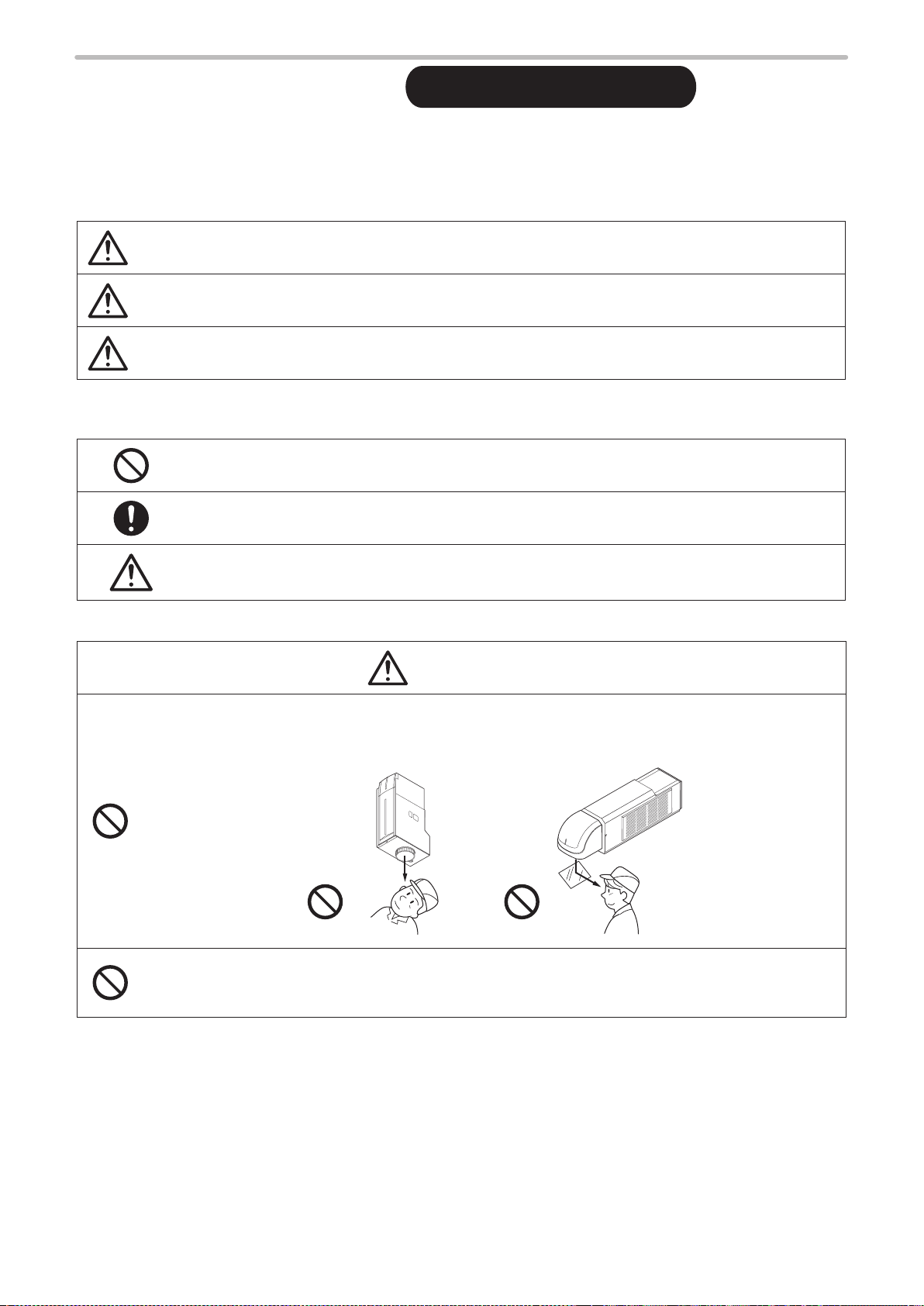
DANGER
• Never look at laser beam directly, through lens or through any other optical components. Laser beam
radiation into the eye causes blindness or serious damage to the eye.
Not only the direct beam of laser, but also diffused reected beam is harmful.
• Never touch laser beam and avoid human skin, clothing and any other ammable object from laser beam
exposure directly.
Burning into deep skin might result and there is a risk of re.
3

WARNING
• Do not use this product anywhere where re is strictly prohibited, near inammable gas, objects or organic
ME-LP400V-EX-6
solvents such as thinner or gasoline, or in dusty place. There is a risk of re.
• Do not use this product in wet place. In addition, never conduct wiring or maintenance work with wet hands
or when the product surface is wet. Otherwise, electric shock and/or malfunction may result.
• Never disassemble the product.
Doing so may cause exposure to the laser beam or electric shock.
• Do not insert hands or objects between the gaps of the exhaust port or inspiratory port.
There is a risk of electrical shock or injury.
• For LP-V / LP-W series, be careful neither to give strong power to the ber cable nor to nip it for installation.
Do not install the product to the systems that give excessive load acts on the ber cable, such as head
movement unit.
If the ber cable is damaged, laser beam comes out from the cable and it may cause laser exposures.
• Take laser protection measures required to use Class 4 laser products subject to the local laws and
regulations of the country or region in which this laser product is used.
• To protect the operators’ eyes, make it mandatory to wear goggles against laser beam
within the laser controlled area. The protective goggles can momentarily protect the
eyes against the scattered beam. Never look at the direct beam or reected beam
even when you are wearing the protective goggles.
• Construct an interlock systems such as a function to stop laser radiation for the maintenance door of the
protective enclosure.
• Set protective enclosure with proper reectance, durability and thermal resistance to enclose the laser
radiation area without leakage.
• After power supply of laser marker is turned off, laser safety manager must remove the key and keep it.
• Be sure to connect the head to the exclusive controller. It will cause exposure of laser beam and a failure if it
connects with any equipment other than the exclusive controller.
• Read all packaged guides and manuals thoroughly, and do not operate, install and connect the laser marker
with any other methods except the instructions provided in the manuals. Inappropriate use might cause
injury, electrical shock or exposure of laser beam.
4
WARNING
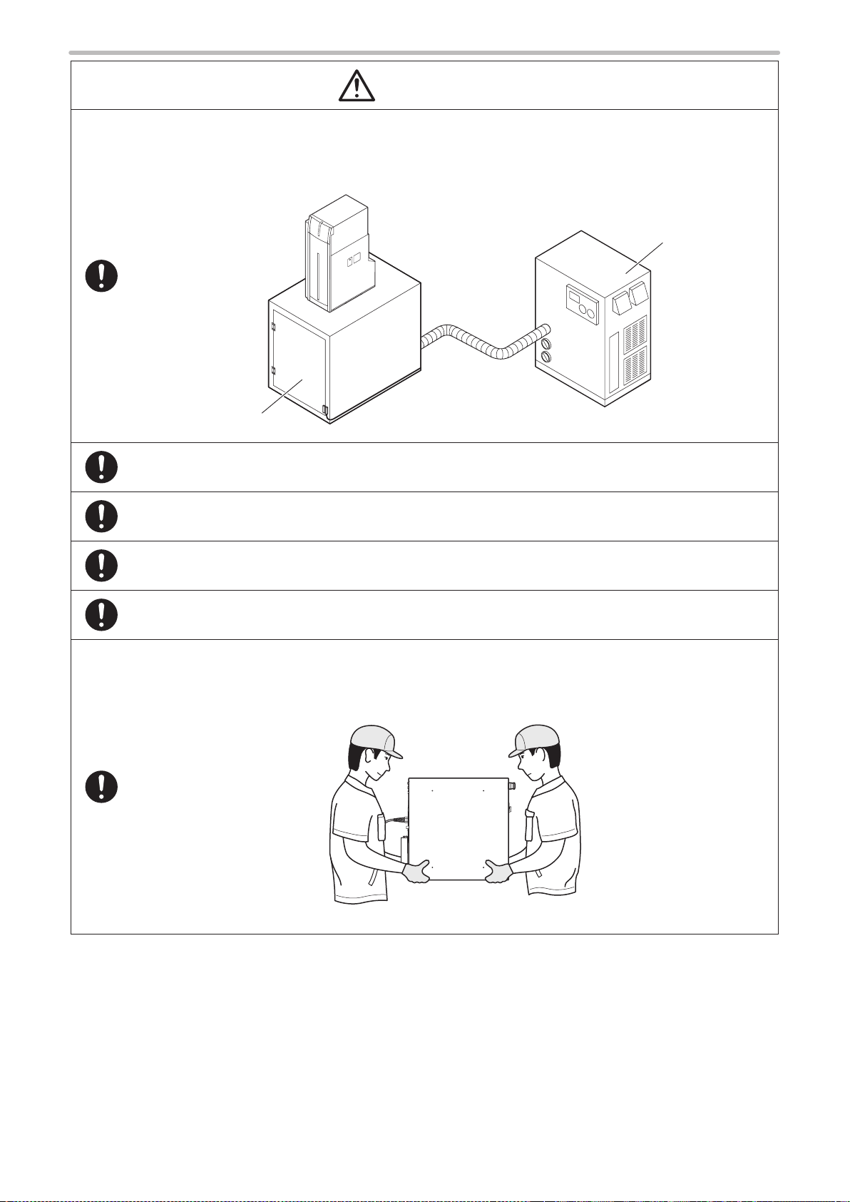
• Remove the dust and/or gas which may be generated during the laser radiation with dust collector or
ME-LP400V-EX-6
exhauster. Use an appropriate dust collector or exhauster for dust or gas generated.
Depending on the material of the objects, harmful dust and/or gas to the human body and the laser marker
may be generated.
Dust collector
Protective enclosure
• When using the assist gas for laser processing, take safety precautions to protect operators from exposure,
ignition, toxic effect, excess or lack of oxygen.
• Prior to wiring, cable connecting, and/or maintenance work, ensure that all the power switches are turned
off. Otherwise, electrical shock may result.
• The wiring and maintenance must be conducted by the electrical engineers or under their supervision.
Incorrect work may cause electrical shock.
• Connect ground wire before using. A failure or electrical leakage that occurs when the unit is not properly
grounded may result in electric shock.
• To carry this product, wear the non-slip gloves and safety shoes, hold the bottom of the unit as shown below
gure. Carry the controller unit with two persons.
• Install this product in the stable place without vibration and shock.
• In case it falls down, it may cause injury.
Controller
5

For the Proper Use of Product
ME-LP400V-EX-6
• Be sure to observe the following matters to prevent a failure or a malfunction of this product and to maintain
the product performance properly.
Usage environment
• Do not use the product in a place with frequent vibrations or shocks. Moreover, please do not drop this product. It
may affect the precision component and optical component inside, which could impair the performance or result in a
failure.
• Do not use the system outdoors.
• The product is air-cooled. Please install not to bar the ow of air cooling. Avoid placing heat sources near the product.
• Be sure to use the product within the ambient temperature and humidity dened in the specications.
• Be careful not to have water, oil, ngerprints, dust, or dirt attached to the laser emission port of the head. This could
degrade the lasing performance and may result in a failure. If the laser emission port becomes dirty, use a dry soft
cloth to clean the port.
• If the air lter becomes dirt, clean the lter. Failure to do so may hinder the air ow, resulting in failure of this product.
Replace air lter periodically.
• Ensure that the dust or gas are removed by placing the intake duct of the dust collector or exhauster near the source
of dust or gas. Any dust or gas contamination on the laser emission port may cause failure or decrease the laser
marking or processing quality. In addition, when the laser beam is blocked by dust or gas, it may cause decrease in
laser marking or processing quality.
Installation and mounting
• Do not hold the cables and connectors at carrying this product.
• Do not touch the laser emission port on the bottom of the head. They may affect the laser marking quality badly.
• For LP-V / LP-W series, do not grasp the ber unit when carrying the head part.
• Carry the head as shown in the gure below.
LP-400 series
OK
LP-V/LP-W series
OK
• Do not install the product to the systems that give excessive load acts on the head and cables, such as head
movement unit. Failure to do so may damage the head precision parts or disconnect the cables, resulting in a failure.
• Be careful neither to give strong power to the cables nor to nip it for installation.
• Verify the minimum bend radius of each cable and install them without excess forces being applied.
• Do not hit the device with a tool such as a hammer at the installation. Do not use excessive force while tightening the
screws (nuts). It may cause a failure.
• Do not insert any objects between the gaps of the exhaust port or inspiratory port.
• Use anti-reection material (ex. black paint for metal) for an external shutter or a protective enclosure in a path of
laser beam. It may cause a failure of the components inside the laser marker head.
• If any other devices such as a sensor or a camera are installed near the laser marker, make sure that these devices
are installed in the place where laser beam and its reected beam do not damage to them.
NG
NG
Fiber cable
Laser emission port
Laser pointer emission port
6

For the Proper Use of Product
ME-LP400V-EX-6
• Be sure to observe the following matters to prevent a failure or a malfunction of this product and to maintain
the product performance properly.
Wiring
• Verify that the cables are wired correctly before powering on.
• For the connection of this product, use the dedicated cables attached to the product or the specied optional cables.
• Check the voltage uctuations of the power supply. Do not input the power supply exceeding the rating.
• If a surge occurs in the power supplied, connect a surge absorber to a source of the surge to absorb it.
• Be sure to take measures against surge before connecting any induction load such as DC relay to the load.
• The output has no protection function for short-circuit, therefore, do not connect the power supply or capacitive load
directly.
• Make sure to ground the frame ground terminal of this product.
• Install such that the controller housing and the head housing are at the same electric potential.
• Each connecting cable should not be used in the same raceway or connected in parallel to any device that generates
high-tension wires, power lines, large switching surge or the like. There is a risk of malfunction caused by induction.
• USB cable should not be connected in parallel with the controller power cable or the motor power cable.
• Make the wiring as short as possible to prevent a malfunction by the noise.
Operation
• Do not turn off the power supply until completing the system start.
• In case of turning ON the power supply after turning OFF, leave the interval at least 5 seconds between ON and OFF.
• The following items, Date, Lot, and Expiry Date are marked based on the internal clock of the laser marker. The
internal clock might be deviated due to error of the internal parts or degree of the battery drain, ambient temperature
and humidity. Therefore, be sure to check the time of the internal clock before the operation.
• Do not remove the USB media nor turn off the power during the data writing and reading operation.
Others
• Be sure to delete all registered data when transferring or discarding this product. Retained data might result in illegal
read out and leaking of information by a third-party with malicious intent.
7
How to Read this Document
ME-LP400V-EX-6
Target laser marker
⿎
This document is subject to the following Laser Marker models.
In this document, “laser marker” means this product.
If the setting contents or specications vary by models, the target models are specied in the text. (The target models are
not specied for items which are common to all models.) In the text, multiple models may be described collectively, as
shown in the table below.
Note that the illustration and the screen images may vary with model.
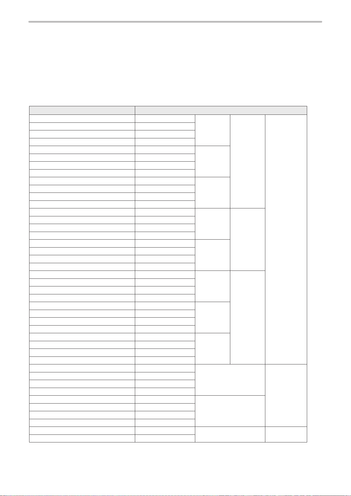
Target model Description in the text
LP-430U, LP-430TU LP-4xx(T)U LP-430 LP-4x0 LP-400 Series
LP-430U-A, LP- 430TU-A LP-4xx(T)U-A
LP-430U-C, LP-430TU-C LP-4xx(T)U- C
LP-430U-CHN, LP-430TU-CHN LP-4xx(T)U-CHN
LP-420S9U, LP-420S9TU LP-4xxS9(T)U LP-420
LP-420S9U-A, LP-420S9TU-A LP-4xxS9(T)U-A
LP-420S9U-C, LP-420S9TU- C LP-4xxS9(T)U-C
LP-420S9U-CHN, LP- 420S9TU-CHN LP-4xxS9(T)U-CHN
LP-410U, LP-410TU LP-4xx(T)U LP-410
LP-410U-A, LP-410TU-A LP-4xx(T)U-A
LP-410U-C, LP-410TU-C LP-4xx(T)U-C
LP-410U-CHN, LP-410TU-CHN LP-4xx(T)U-CHN
LP-435U, LP-435TU LP-4xx(T)U LP-435 LP-4x5
LP-435U-A, LP-435TU-A LP-4xx(T)U-A
LP-435U-C, LP-435TU-C LP-4xx(T)U- C
LP-435U-CHN, LP- 435TU-CHN LP-4xx(T)U-CHN
LP-425S9U, LP-425S9TU LP-4xxS9(T)U LP-425
LP-425S9U-A, LP-425S9TU-A LP-4xxS9(T)U-A
LP-425S9U-C, LP-425S9TU-C LP-4xxS9(T)U-C
LP-425S9U-CHN, LP- 425S9TU-CHN LP-4xxS9(T)U-CHN
LP-431U, LP-431TU LP-4xx(T)U LP-431 LP-4x1
LP-431U-A, LP-431TU-A LP-4xx(T)U-A
LP-431U-C, LP-431TU-C LP-4xx(T)U- C
LP-431U-CHN, LP-431TU-CHN LP-4xx(T)U-CHN
LP-421S9U, LP-421S9TU LP-4xxS9(T)U LP-421
LP-421S9U-A, LP-421S9TU-A LP-4xxS9(T)U-A
LP-421S9U-C, LP-421S9TU-C LP-4xxS9(T)U-C
LP-421S9U-CHN, LP- 421S9TU-CHN LP-4xxS9(T)U-CHN
LP-411U, LP-411TU LP-4xx(T)U LP-411
LP-411U-A, LP-411TU-A LP-4xx(T)U-A
LP-411U-C, LP- 411TU-C LP-4xx(T)U-C
LP-411U-CHN, LP-411TU-CHN LP-4xx(T)U-CHN
LP-V10U LP-VxxU LP-V10 LP-V Series
LP-V10U-A LP-VxxU-A
LP-V10U-C LP-VxxU-C
LP-V10U-CHN LP-VxxU-CHN
LP-V15U LP-VxxU LP-V15
LP-V15U-A LP-VxxU-A
LP-V15U-C LP-VxxU-C
LP-V15U-CHN LP-VxxU-CHN
LP-W052U LP-W052U LP-W052 LP-W Series
LP-W052U-A LP-W052U-A
8

Symbol indications
ME-LP400V-EX-6
⿎
Notice
Reference
Type of manuals
⿎
For this product the following manuals are prepared. Read each manuals and operate this product correctly and safely.
Save the manuals for future use.
• “Notice” denotes any instructions or precautions for using this product. To prevent the
damage or malfunction of the product, observe these precautions fully.
• “Reference” denotes any hints for operation, detail explanations, or references.
Operation/Maintenance Manual
This manual describes the safety precautions and the items required for the installation, operation and maintenance of
the laser marker.
• Precautions and safety measures: All users shall be required for reading this part.
• Specications and outer dimensions
• Setup and connecting method
• How to operate the laser marker and set the marking data using touch panel console or monitor and mouse.
• Maintenance
• Troubleshooting
External Control Manual
This manual describes how to control this product externally using I/O signals and serial communication (RS-232C/
Ethernet) commands.
Mainly the machine builder and system integrator shall be required for reading this manual.
• I/O control method (interfaces, signal layout, I/O rating, timing chart etc.)
• Command control method (serial communication interfaces, communication settings, command data formats etc.)
Laser Maker NAVI Operation Manual
This manual describes how to operate the laser marker and set the marking data using PC setting software “Laser
Marker NAVI”.
Reference
• The PDF data of each manual are included on an attached CD-ROM “Laser Marker Driver & Utility”.
• To read the PDF manual, Adobe Reader (Version 7 or later) of Adobe Systems Incorporated is required.
9

Contents
ME-LP400V-EX-6
Preface ……………………………………………………………………………… 2
Cautions in Handling
How to Read this Document
………………………………………………………………… 3
……………………………………………………… 8
1 Before External Control …………………………………………… 12
1-1 Operation Method for Laser Marker …………………………………………13
1-1-1 Operation procedure of test marking and run mode …………………… 14
1-1-2 Test marking and run mode operation …………………………………… 15
1-2 Operation by External Devices ………………………………………………16
1-2-1 Operation method using external control device ………………………… 16
1-2-2 Operation procedure with external control ………………………………… 17
1-3 Before External Control ………………………………………………………18
1-3-1 DIP switch setting …………………………………………………………… 19
1-3-2 Communication condition setting ………………………………………… 21
1-3-3 Shift to remote mode ………………………………………………………… 23
2 Control by I/O ……………………………………………………… 24
2-1 I/O Interface Specication ……………………………………………………25
2-1-1 I/O terminal block …………………………………………………………… 26
2-1-2 I/O connector ………………………………………………………………… 26
2-1-3 Signals and details of I/O terminal block ………………………………… 27
2-1-4 Signals and details of I/O connector ……………………………………… 33
2-2 Input/Output Rating ……………………………………………………………40
2-2-1 Input rating and input circuit ………………………………………………… 40
2-2-2 Output rating and output circuit …………………………………………… 41
2-3 Connecting I/O Terminal Block ………………………………………………42
2-3-1 Connecting samples (Independent operation of laser marker) ………… 42
2-3-2 Connecting sample with external devices ………………………………… 44
2-4 Timing Chart ……………………………………………………………………46
2-4-1 Basic input/output …………………………………………………………… 46
2-4-2 Marking trigger input ………………………………………………………… 47
2-4-3 Equidistant marking (Flying object marking) ……………………………… 47
2-4-4 Select le ……………………………………………………………………… 48
2-4-5 Time hold ……………………………………………………………………… 49
2-4-6 Counter end ………………………………………………………………… 49
2-4-7 Count-up/Count-down value correction …………………………………… 50
2-4-8 Counter reset ………………………………………………………………… 51
2-4-9 Rank/Offset marking ………………………………………………………… 52
2-4-10 Laser stop input …………………………………………………………… 53
2-4-11 Emergency stop input ……………………………………………………… 54
10

3 Control by Serial Communication (RS-232/Ethernet) ………… 56
ME-LP400V-EX-6
3-1 Preparation of Command Control ……………………………………………57
3-1-1 RS-232C ……………………………………………………………………… 57
3-1-2 Ethernet ……………………………………………………………………… 60
3-2 Command Reception Condition ………………………………………………62
3-3 Connection Check ………………………………………………………………63
3-4 Control Sample …………………………………………………………………64
3-5 Communication Data Format …………………………………………………68
3-5-1 Command data ……………………………………………………………… 68
3-5-2 Response data ……………………………………………………………… 69
3-5-3 Communication sequence ………………………………………………… 72
3-6 Communication Command List ………………………………………………74
3-7 Command Description …………………………………………………………78
Troubleshooting …………………………………………………… 141
Troubleshooting …………………………………………………………………… 142
Error Indication
Alarm ………………………………………………………………………………… 151
Warning
…………………………………………………………………… 151
……………………………………………………………………………… 154
Character Code Table ……………………………………………… 158
ASCII Code………………………………………………………………………… 159
Original Font
JIS Level-1 Font…………………………………………………………………… 161
JIS Level-2 Font…………………………………………………………………… 167
User Registration Character Font
……………………………………………………………………… 160
……………………………………………… 175
Index ………………………………………………………………… 176
Index ……………………………………………………………………………… 177
11

1 Before External Control
ME-LP400V-EX-6

1-1 Operation Method for Laser Marker
CAUTION
ME-LP400V-EX-6
• It is obligated by IEC/FDA/JIS that laser products shall incorporate a keyactuated master control. Actuation of this product is basically controlled by
the key switch located on the front of the controller. However, in considering
situations when the laser marker is operating as a part of a larger system, the
laser marker turns on if the key switch is already in ON position, and power is
supplied. In this case, be sure that the external system controls the operation
of the laser marker with a key-actuated master control.
The laser marker can be controlled by the following method:
Control by the manually screen operation
To irradiate the laser by the screen operation, select the control methods from the followings:
• Test marking
Test marking executes the laser radiation manually with the selected
le.
Use Test marking when you want to check the marking results while
changing the setting parameters, such as during the testing to nd
the appropriate parameters or the maintenance work.
ABCI
• Run mode operation
Run mode is an operation method to congure the settings of the
laser marker by manual screen operation and to control the marking
start signal from the external devices such as switches or sensors
connected to I/O terminal.
Use this operation mode to congure the laser marker without using the
external control devices as PLC.
Reference
• Refer to “1-1-2 Test marking and run mode operation” (P.15).
• For the setting details, refer to Operation/Maintenance manual.
Control by external devices (remote control mode)
The operation method for automatic control.
I/O or communication commands control the operations such as
laser pumping and marking by connecting the laser marker to the
external control device as PLC.
The following external control methods are available. These
controls can be combined.
• I/O control
• Communication command control (RS-232C/Ethernet)
Touch panel console
or monitor and mouse
ABC
ABCD
Sensor for the
marking trigger
ABC
• For details on the external control, refer to “1-2 Operation by
Reference
External Devices” (P.16).
External control
device such as PLC
13

1-1-1 Operation procedure of test marking and run mode
ME-LP400V-EX-6
This section describes the basic operation procedures with the display operation connected to the controller.
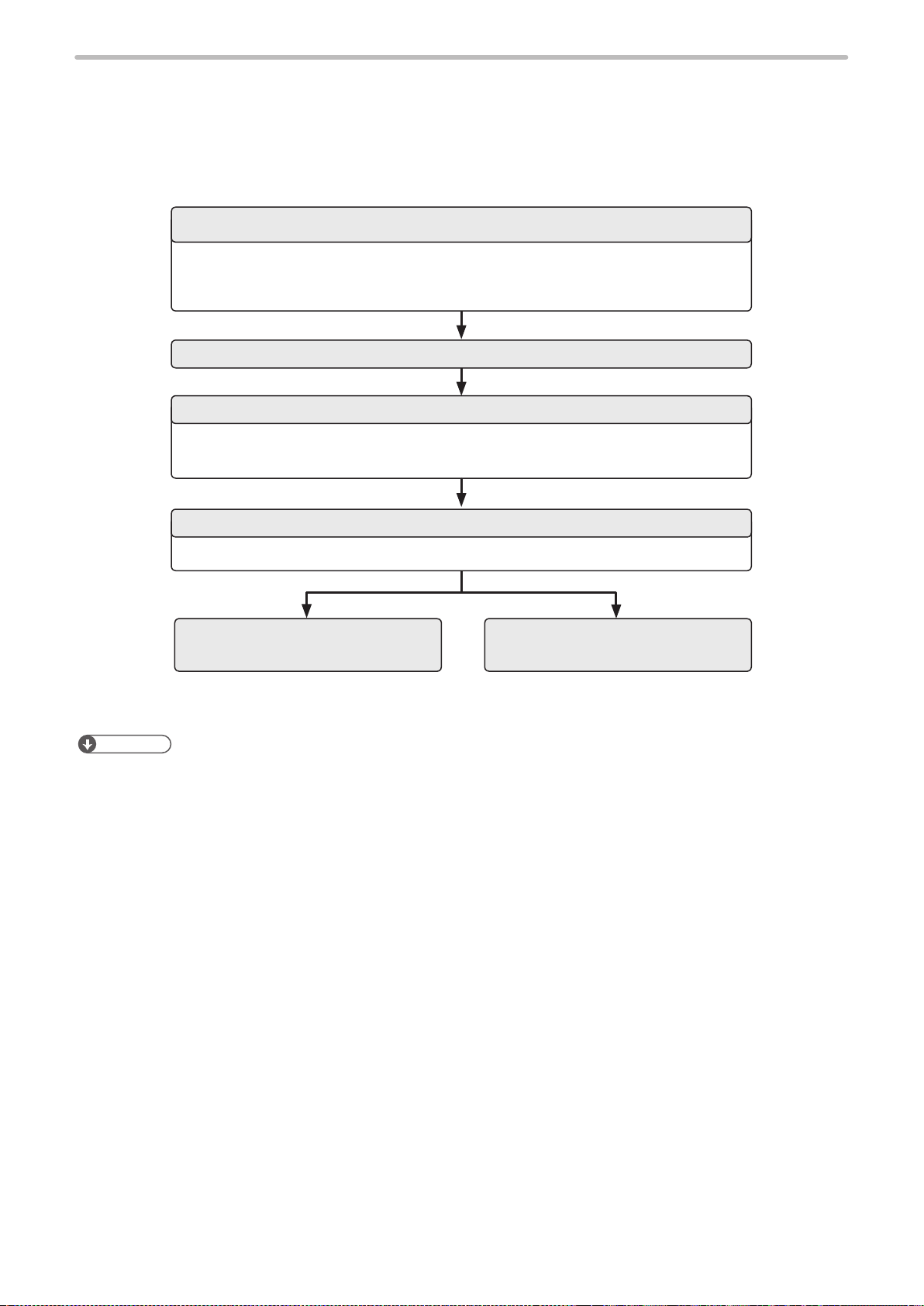
Flow chart
⿎
Turn on power with key switch on controller.
For test marking For run mode operation
File selection
Edit the le
Turn on laser pumping. (Complete in 15 to 20 sec.)
Start test marking
Open internal shutter. (Self-opening)
Marking (Laser radiation)
Edit and overwrite the le
Select le to use in run operation.
Start run operation.
Marking trigger input
Input TRIG. IN (A4) on I/O terminal to start marking.
14
Save the le.
Turn off laser pumping.
Turn off power.
1-1-2 Test marking and run mode operation
ME-LP400V-EX-6
To irradiate the laser by the screen operation, operate the laser marker in test marking or run mode operation.
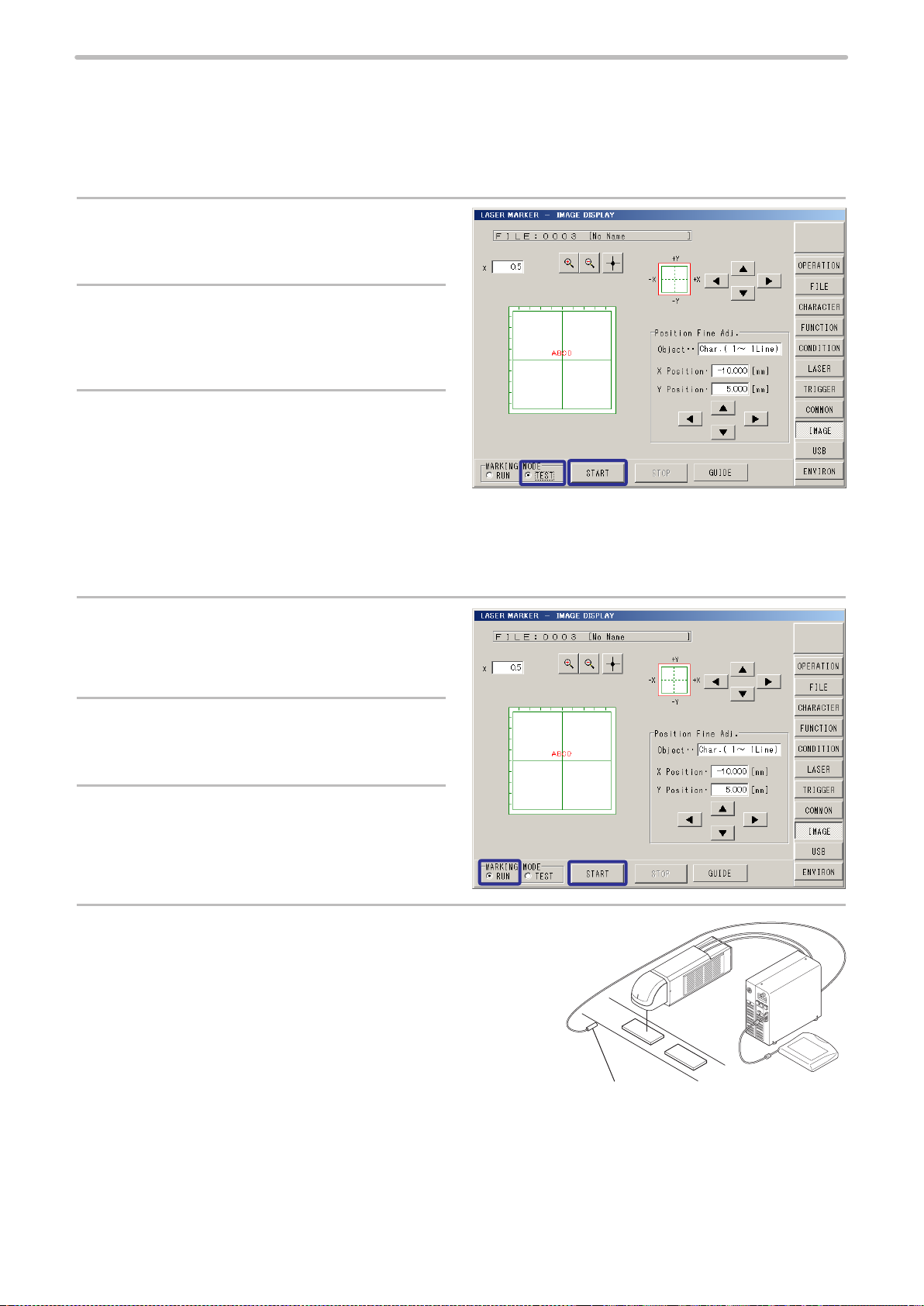
Test marking procedure
⿎
Test marking executes the laser radiation manually with the selected le.
Select “TEST” of the marking mode in the
1.
lower part of the screen.
Turn ON the laser pumping switch on the
2.
controller to start laser pumping.
To start marking, click “START”.
3.
Run mode procedure
⿎
Run mode is an operation method to congure the settings of the laser marker by manual screen operation and to control
the marking start signal from the external devices such as switches or sensors connected to I/O terminal.
Set the marking mode to “RUN”.
1.
Turn ON the laser pumping switch on the
2.
controller to start laser pumping.
Click “START”.
3.
Under the RUN mode operation, the laser marker is in
the standby status for the marking start signal from I/O
terminal A4: TRIG. IN.
Laser radiation starts by inputting the marking trigger on
4.
the I/O terminal.
Connect a switch or sensor to A4: TRIG. IN. on the I/O terminal as
the input method of the marking start signal (trigger).
ABC
ABCD
Sensor for the
marking trigger
15

1-2 Operation by External Devices
ME-LP400V-EX-6
1-2-1 Operation method using external control device
To control the laser marker with the external control device, the following connecting methods are applicable:
External control using I/O : Remote mode operation
Controls the laser marker from external devices such as PLC using various I/O signals loaded into the laser marker.
For details, refer to “2 Control by I/O” (P.24).
I/O terminal block
I/O connector
ABC
PLC, etc.
External control by serial communication commands (RS-232C/Ethernet) : Remote mode operation
Controls the laser marker from external devices such as PLC using communication commands via RS-232C or Ethernet.
For details, refer to “3 Control by Serial Communication (RS-232/Ethernet)” (P.56).
Ethernet or
RS-232C
ABC
External control device
16
Reference
• It is available to the external control combining I/O, and serial communication commands.
• To input marking trigger with I/O and congure other settings with a screen operation manually, use Run mode. For
details, refer to “1-1-2 Test marking and run mode operation” (P.15).

1-2-2 Operation procedure with external control
ME-LP400V-EX-6
Operation example when controlling the laser marker from external control devices such as
⿎
PLC
Turn ON key switch of laser marker controller
Remote mode ON
Refer to “1-3-3 Shift to remote mode” (P.23).
I/O control
Select le
Laser pumping ON
Open shutter
READY output ON
The device is ready for receiving the marking starting signal (trigger).
Marking trigger input ON
Marking (Laser radiation)
Reference
Control by serial communication commands
about 15 to 20 seconds
Control by using I/O
or communication
commands
• It is available to the external control combining I/O, and serial communication commands.
• Congure the environment setting on the I/O communication in advance before using external control. Refer to “1-3
Before External Control” (P.18).
17
1-3 Before External Control
ME-LP400V-EX-6
The following settings are required before the external control by using I/O or communication commands.
Setting ow to start external control
⿎
DIP switch setting
• DIP switch No. 2: Select control method, I/O or command for some specic operations.
• DIP switch No. 5 and No. 6: Select setting method of remote mode.
Refer to “1-3-1 DIP switch setting” (P.19).
Turn ON laser marker
Communication environment setting
Set I/O and communication conditions in the environment setting screen.
Refer to “1-3-2 Communication condition setting” (P.21).
Remote mode ON
Refer to “1-3-3 Shift to remote mode” (P.23).
I/O control
Reference
• For the installation and the setup of the laser marker, refer to Operation/Maintenance manual.
Control by serial communication
commands
18
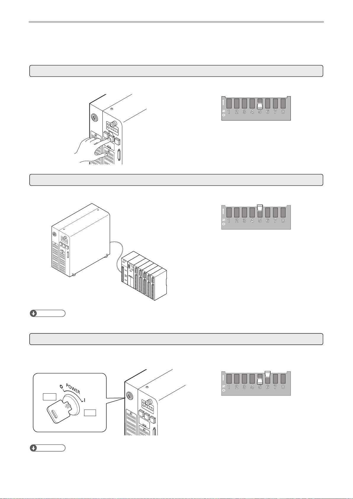
1-3-1 DIP switch setting
ME-LP400V-EX-6
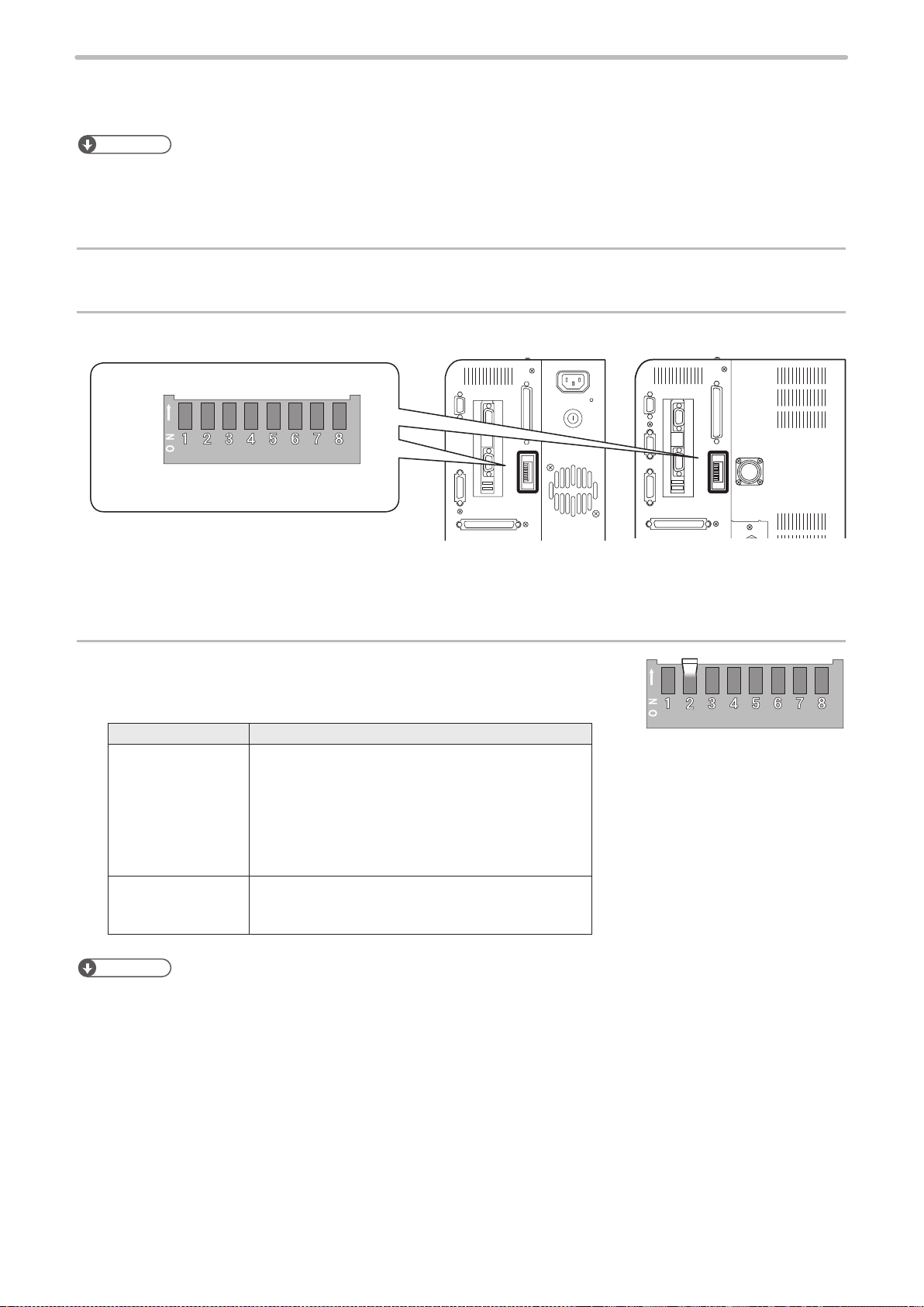
Set the operational options for the external control with the DIP switch equipped on the controller rear side.
Reference
• The initial setting of all DIP switches is OFF.
• Turn OFF the power at DIP switch setting.
• For the details on DIP switch, refer to Operation/Maintenance manual.
Turn OFF the power of laser marker.
1.
Remove the DIP switch cover on the rear of the controller.
2.
ON
OFF
DIP switch
LP-400 series LP-V/LP-W series
Rear of controller
With DIP switch No. 2, select the control method, I/O or command
3.
for some specic operations.
DIP switch No. 2 Control method for specic operations
ON Control by serial communication commands for the
following operations
• Laser pumping (LSR)
• Shutter control (SHT)
• Guide laser (GID)
• Laser check radiation (SPT)
• Power check (PWR) (LP-V/LP-W series only)
OFF (initial setting) Control by I/O for the following operations
• Laser pumping
• Shutter control
Reference
• “Guide Laser Control”, “Laser Check Radiation” and “Power Check” cannot be controlled by I/O. They can be controlled
only by using serial communication in the remote mode.
19
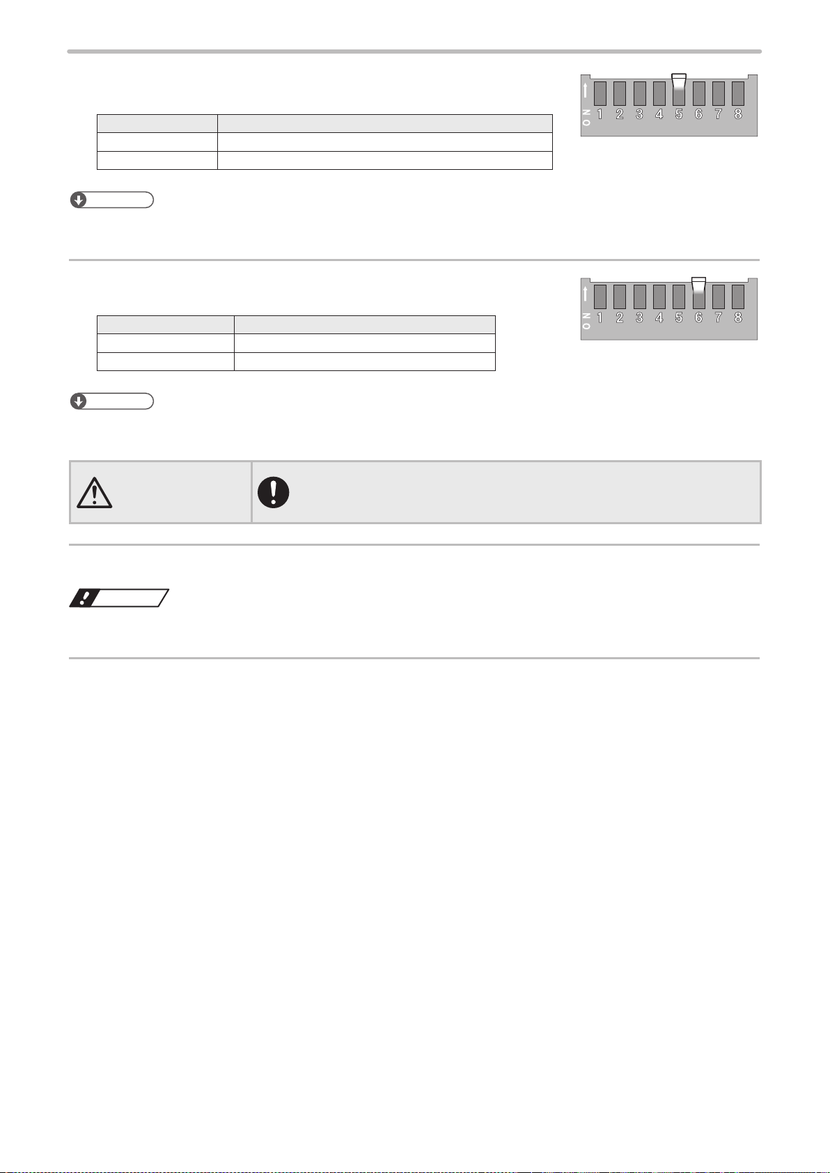
With DIP switch No. 5, select the setting method of the remote
CAUTION
ME-LP400V-EX-6
4.
mode.
DIP switch No. 5 Setting method of remote mode
ON Use the input signal of REMOTE IN (A3) on I/O terminal.
OFF(initial setting) Use the remote switch on the front of the controller.
Reference
• When DIP switch No. 5 is ON, the remote switch on the controller is not available.
When DIP switch No. 5 is OFF, select the remote mode state at
5.
powered ON with DIP switch No. 6.
DIP switch No. 6 Remote mode state at powered ON
ON Starts up with remote mode ON
OFF (initial setting) Starts up with remote mode OFF
Reference
• When DIP switch No. 5 is ON, keep DIP switch No. 6 OFF.
• When DIP switch No. 6 is ON, “X5: REMOTE IN” signal on I/O terminal is not available.
• If the DIP switch No. 5 or No. 6 are used while turned on, construct a system
for re-pumping the laser manually as safety protection measures after the stop
of the laser radiation due to an emergency stop or an interlock.
Install the DIP switch cover to the controller.
6.
Notice
• A plastic cover is installed on the DIP switch. Install this cover always to avoid the dust penetration to the controller.
Turn ON the power of laser marker.
7.
20
1-3-2 Communication condition setting
ME-LP400V-EX-6
To control the laser marker by using I/O or communication commands, congure the following items in advance on the
environment setting screen.
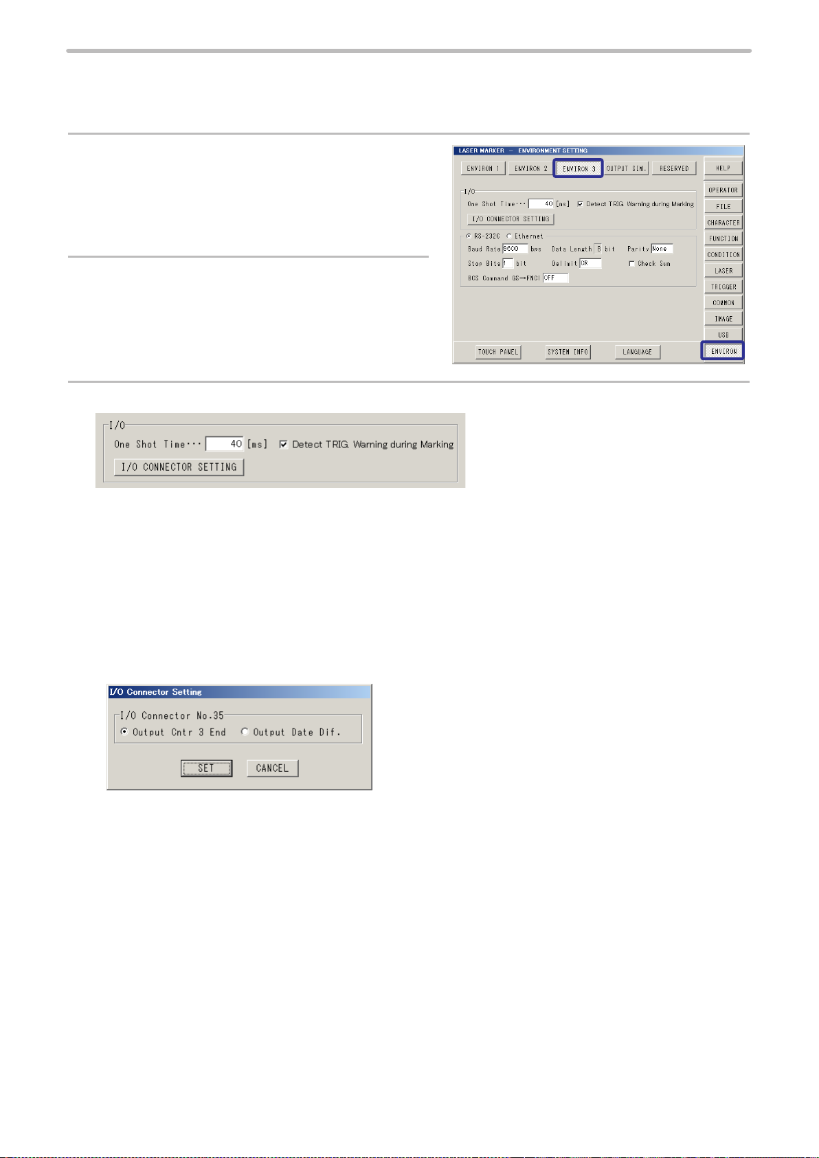
Select “ENVIRON” on the right menu.
1.
Select “ENVIRON 3”.
2.
To use I/O signals, congure the following output conditions:
3.
• One-shot time:
Sets the output duration for some signals such as MARK END OUT and SET OK OUT.
Setting range: 2 ms to 510 ms (initial value is 40 ms)
• Detect TRIG. Warning during Marking
Congure if you will output (ON) or will not output (OFF) the warning for the invalid trigger. With enabling this setting,
the warning is output when the marking trigger that cannot be accepted was input while the shutter is opened.
• I/O Connector Setting
Select the operation of I/O connector signal No. 35 from “Output Counter 3 End” or “Output Date Difference”.
21
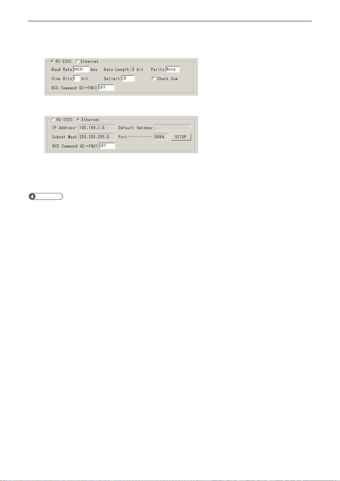
To use the serial communication commands, set communication conditions for Ethernet or RS-
ME-LP400V-EX-6
4.
232C.
• For RS-232C:
Congure the communication conditions of the laser marker corresponding to the external control device.
• For Ethernet:
Congure the communication conditions according to the network environment.
• BCS Command GS to FNC1
This setting is available only when the barcode “GS1 Data Matrix” is used. To set the barcode character by using
serial communication command “BCS”, select either “GS” (OFF) or “FNC1” (ON) as the separator of AI data with the
variable length.
Reference
• The laser marker can be controlled by I/O and communication commands combined.
• RS-232C and Ethernet cannot be used at the same time.
• The parameters on the environment setting screen are applied to the laser marker directly without saving.
• When using RS-232C, specify the “Flow control” to “None” at the communication port settings of the external control
device.
22
1-3-3 Shift to remote mode
ME-LP400V-EX-6
To control the laser marker externally using I/O or serial communication commands, set the operation mode to the remote
mode in one of the following methods.
Select the method to switch to the remote mode by setting the DIP switch on the rear side of the controller.
Use the remote switch on the front of the controller.
Turn ON the remote mode switch on the front of the controller.
Check that DIP switch No. 5 is OFF.
Refer to “1-3-1 DIP switch setting” (P.19).
Use input signal of X5 “REMOTE IN” on I/O terminal.
Turn ON the REMOTE IN (A3) of the I/O terminal on the rear of the controller.
A3: REMOTE IN
Check that DIP switch No. 5 is ON.
Refer to “1-3-1 DIP switch setting” (P.19).
Reference
• When DIP switch No. 5 is ON, the remote switch on the controller is not available.
Start the laser marker in the remote mode.
The laser marker starts up always in the remote mode state. Use the remote mode switch button of the controller for
releasing and resetting the remote mode.
OFF
ON
Reference
• When DIP switch No. 6 is ON, “X5: REMOTE IN” signal on I/O terminal is not available.
• The remote switch on the controller is available when DIP switch No. 6 is ON.
Check that DIP switch No. 5 is OFF, and No. 6 is ON.
Refer to “1-3-1 DIP switch setting” (P.19).
23

2 Control by I/O
ME-LP400V-EX-6

2-1 I/O Interface Specication
ME-LP400V-EX-6
The I/O terminal block and the I/O connector are available as the external control I/O interface of this product.
• I/O terminal block: Loaded with the basic input/output to control the laser marker.
• I/O connector: Loaded with the input/output for data conguration such as selecting a le number and the input/output
for the specic functions.
Reference
• Before using I/O, congure the DIP switch and the environment settings. Refer to “1-3 Before External Control” (P.18).
• I/O terminal block is removable from the controller at the wiring.
Rear of controller
LP-400 series LP-V/LP-W series
Laser marker side
I/O connector (female)
A12
A11
A2
A1
I/O terminal block
B12
B11
B2
B1
When terminal block is detached
1
2
12
13
Laser marker side
D-sub 25 pin connector (female)
14
15
24
25
25
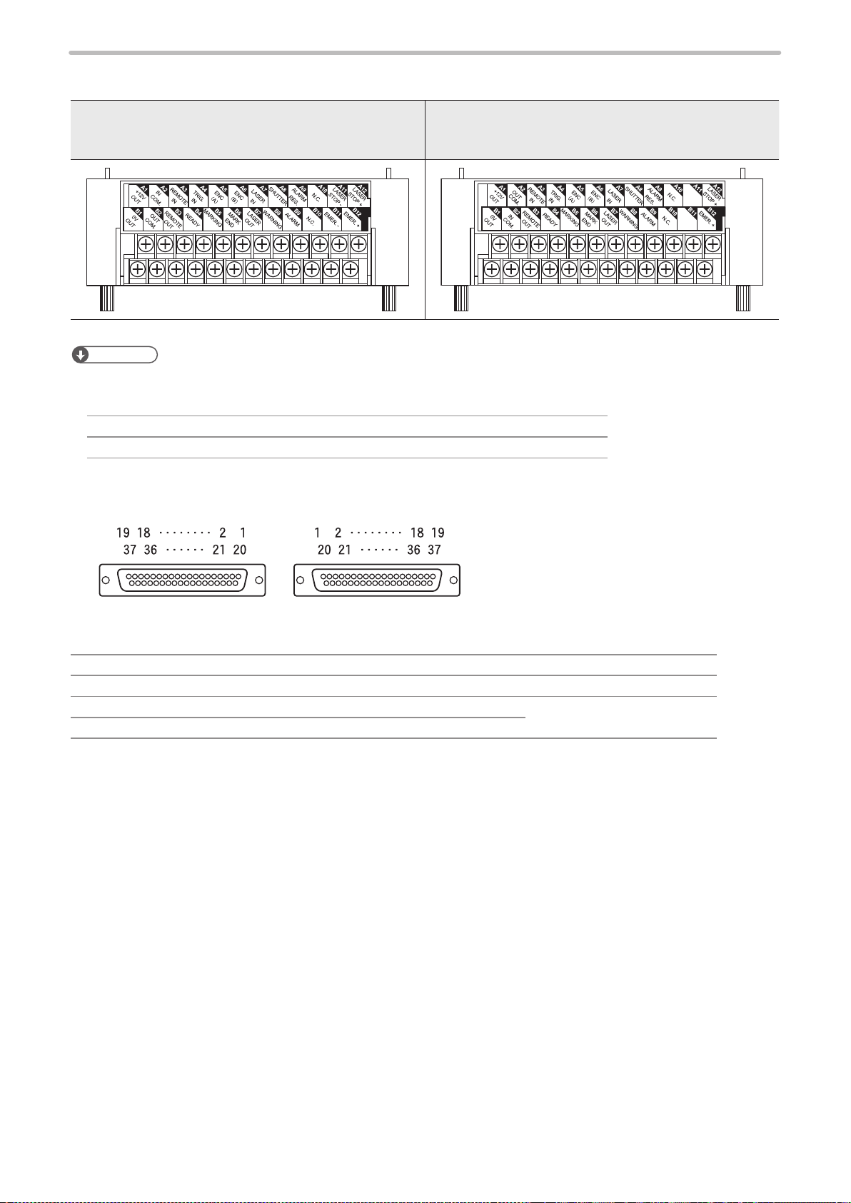
2-1-1 I/O terminal block
ME-LP400V-EX-6
I/O terminal block of the NPN type
[LP-4xx(T)U / LP-4xx(T)U-A / LP- 4xxS9(T)U /
LP-4xxS9(T)U-A / LP-VxxU / LP-VxxU-A / LP-W series]
Reference
• A2, A11, B2 and B11 on the I/O terminal block have different signals depending on the controller type of NPN or PNP.
• The connector type of I/O terminal block is as follows. (When the terminal block is removed.)
Laser marker side connector type Female D-sub 25 pin (Screw type: M2.6, female)
User side connector type Male D-sub 25 pin (Screw type: M2.6, male)
I/O terminal block of the PNP type
[LP-4xx(T)U-C / LP-4xxS9(T)U-C / LP-VxxU-C]
RESERVE
RESERVE
2-1-2 I/O connector
Laser marker side
(Female connector)
Laser marker side connector type Female D-sub 37 pin (Screw type: M2.6, female)
User side connector type Male D-sub 37 pin (Screw type: M2.6, male)
[Attached item] User side connector HDCB-37PF (05)
[Attached item] User side connector cover HDC-CTH1 (10)
User side: Attached accessory
(Male connector)
* This view is facing the connecting surface.
Hirose Electoric Co., Ltd.
26

2-1-3 Signals and details of I/O terminal block
ME-LP400V-EX-6
The I/O terminal block is loaded with the basic input/output to control the laser marker.
Signals in I/O terminal
⿎
No. *1 Signal name
A1
(12)
A2
(11)
A3
(12)
A4
(9)
A5
(8)
A6
(7)
A7
(6)
+12V OUT
I/O power supply +12V DC (Max. 300mA)
• For NPN models *2
IN COM.
Input common
• For PNP models (-C) *2
OUT COM.
Output common
REMOTE IN
Remote mode input
TRIG. IN
Marking trigger input
ENC. A
Encoder A-phase input
ENC. B
Encoder B-phase input
LASER IN
Laser pumping input
No. *1 Signal name
B1
(25)
B2
(24)
B3
(23)
B4
(22)
B5
(21)
B6
(20)
B7
(19)
0V OUT
I/O power supply 0V
• For NPN models *2
OUT COM.
Output common
• For PNP models (-C) *2
IN COM.
Input common
REMOTE OUT
Remote mode output
READY
Marking ready output
MARKING
Marking output
MARK END
Marking end output
LASER OUT
Laser pumping completion output
A8
(5)
A9
(4)
A10
(3)
A11
(2)
A12
(1)
*1 : The numbers in ( ) indicates the pin No. of the D-Sub connector when the terminal block is removed.
*2 : Signals of A2, A11, B2 and B11 are different depending on the controller type of NPN or PNP.
• NPN models: LP-4xx(T)U / LP-4xx(T)U-A / LP-4xxS9(T)U / LP-4xxS9(T)U-A / LP-VxxU / LP-VxxU-A / LP-W series
• PNP models (with “-C” in the end of the model name): LP-4xx(T)U-C / LP-4xxS9(T)U-C / LP-VxxU-C
SHUTTER
Shutter control input
ALARM RES.
Alarm reset input
N.C.
No connection
• For NPN models *2
LASER STOPOutput common for laser stop
• For PNP models (-C) *2
RESERVE
System reservation
LASER STOP +
Laser stop input
B8
(18)
B9
(17)
B10
(16)
B11
(15)
B12
(14)
WARNING
Warning output
ALARM
Alarm output
N.C.
No connection
• For NPN models *2
EMER.Output common for emergency stop
• For PNP models (-C) *2
RESERVE
System reservation
EMER.+
Emergency stop input
Notice
• Use the internal power (A1, B1) as the power supply for the I/O signals when operating the laser marker without external
power supply. Do not connect anything when using the external power supply.
• Do not connect anything to RESERVE terminals.
• Do not mix the connecting pattern for NPN and PNP.
27
Operation of input signal on I/O terminal block
ME-LP400V-EX-6
⿎
Reference
• The ON/OFF listed in this section refers to the ON/OFF operations. It does not refer to the voltage level (High/Low).
No. Name/Description
A1 +12V OUT: Internal power supply + 12V DC (max. output current 300mA)
Use this terminal as the power supply for the I/O signals when operating laser marker without external power
supply.
This terminal can be also used as the power supply for external devices such as a sensor or an encoder.
Notice
• Make sure to use B1 (0V OUT) for the 0V of the internal power A1 (+12V OUT). Do not mix the connecting pattern for
using external and internal power supply.
• Do not connect anything to this when using the external power supply for I/O control.
• When using the internal power supply (A1, B1), the total current of the power supply for the external device and the
consumption current for the I/O control should be less than 300mA.
A2
• For NPN models *1
IN COM.: Input common
The common terminal for each input of the I/O terminal and I/O connector. This A2 and No. 1 of I/O connector
are the common terminals connected internally.
For NPN models, this terminal is connected to the “+ (plus)” side of power which is used for control.
• For PNP models (“-C” in the end of the model name) *1
OUT COM.: Output common
The common terminal for each output of the I/O terminal and I/O connector. This A2 and No. 1 of I/O connector
are the common terminals connected internally.
For PNP models, this terminal is connected to the “+ (plus)” side of power which is used for control.
Notice
• Do not invert the power wiring of I/O terminal and I/O connector. It may cause a failure. When this terminal is connected
to the power supply, it is not necessary to supply the power to the other IN COM. or OUT COM. on I/O connector.
• At the factory shipments, IN COM. and OUT COM. of I/O terminals are connected to the power supply terminals by
short bars respectively. When using the external power supply or connecting to any external devices, remove the short
bars from the terminals to be used.
• Short-circuiting IN COM. and OUT COM. in supplying power might cause the short out and also cause the failure with
the laser marker. Be sure to check the wiring before starting the laser marker.
Reference
• Connect IN COM. and OUT COM. to the power supply respectively.
28
NPN type of laser marker: A2 [IN COM.] ― +V, B2 [OUT COM.] ― GND
PNP type of laser marker: B2 [IN COM.] ― GND, A2 [OUT COM.] ― +V
• For the connecting details, refer to “2-3 Connecting I/O Terminal Block” (P.42).
A3 REMOTE IN: Remote mode input
While this input is turned on, the laser marker operates in the remote mode which can be controlled externally
by I/O and serial communication commands.
To transit to the remote mode using this terminal, turn ON the DIP switch No. 5 in advance.
Refer to “1-3-3 Shift to remote mode” (P.23).
A4 TRIG. IN: Marking trigger input
Marking start signal. This signal can be accepted while READY OUT (B4) is turned ON.
Starts marking (laser radiation) by edge of input ON.
At equidistant marking to the ying object, marking is performed while this input is ON.
No. Name/Description
CAUTION
ME-LP400V-EX-6
A5A6ENC. A: Encoder A-phase input
ENC. B: Encoder B-phase input
Encoder input at marking to the ying object. Input up to 100kHz is possible for A and B phases respectively.
If either inputs of A and B phases are used, connect only ENC.A (A5) with the encoder and connect ENC.B (A6)
to IN COM.
A7 LASER IN: Laser pumping input
While this input is turned on, the laser is pumped to enable the radiation.
It takes approximately 15 to 20 seconds from turning on LASER IN (A7) to completion of laser pumping.
This terminal is available when the DIP switch No. 2 is turned OFF.
A8 SHUTTER: Shutter control input
While this input is turned on, the internal shutter opens. There is a delay time of around 200ms to max. 1
second from turning ON/OFF of SHUTTER (A8) for the actual shutter open / close operation time.
This terminal is available when the DIP switch No. 2 is turned OFF.
Reference
• For LP-400 series, the shutter cannot open until the laser pumping is completed.
• Do not use SHUTTER (A8) input as the emergency stop or the interlock. If
SHUTTER (A8) input becomes ON during laser emission, the shutter is closed
after the marking operation has been nished.
A9 ALARM RES.: Alarm reset input
The reset input for restoring the system from the alarm status.
Make sure to verify the safety by eliminating the alarm causes before turning this input ON.
For the alarms you are unable to reset such as the ones caused by hardware or system error, restart the laser
marker.
A10 N.C.: No connection
Do not use this terminal.
A11
• For NPN models *1
LASER STOP-: Output common for laser stop
This terminal is connected to OUT COM. (B2) internally.
Connect A11 with LASER STOP+ (A12) to release the laser stop warning or alarm and change the status of the
laser marker into valid for laser emitting.
The function relating to safety must be shut off mechanically. Therefore, it is recommended to wire these
terminals at no-voltage contact (dry contact).
• For PNP models (“-C” in the end of the model name) *1
RESERVE: System reser vation
Do not connect externally.
Notice
• A11 and B11 on the I/O terminal block are available only for NPN type of laser marker. For PNP type, do not use these
terminals.
A12 LASER STOP+: Laser stop input
*1 : Signals of A2, A11, B2 and B11 are different depending on the controller type of NPN or PNP.
Use this terminal to stop the laser radiation or disable the laser radiation temporarily by connecting with the
safety devices such as a door or a switch.
When between LASER STOP+ (A12) and OUT COM. (for NPN models; A11 or B2, for PNP models; A2) are
disconnected, the laser radiation will be disabled.
Opening this terminal, changes the status of the laser marker as follows.
• When laser is not emitted: The internal shutter is closed.
• During laser emission: The internal shutter is closed and laser pumping turns off.
The function relating to safety must be shut off mechanically. Therefore, it is recommended to wire these
terminals at no-voltage contact (dry contact).
• NPN models: LP-4xx(T)U / LP-4xx(T)U-A / LP-4xxS9(T)U / LP-4xxS9(T)U-A / LP-VxxU / LP-VxxU-A / LP-W series
• PNP models (with “-C” in the end of the model name): LP-4xx(T)U-C / LP-4xxS9(T)U-C / LP-VxxU-C
29
Operation of output signal on I/O terminal block
ME-LP400V-EX-6
⿎
Reference
• The ON/OFF listed in this section refers to the ON/OFF operations. It does not refer to the voltage level (High/Low).
Terminal
No.
B1 0V OUT: Internal power supply 0V
Name/Description
Use this terminal as the power supply for the I/O signals when operating laser marker without external
power supply.
This terminal can be also used as the power supply for external devices such as a sensor or an encoder.
Notice
• Make sure to use +12V OUT (A1) for the internal power supply with this 0V OUT (B1). Do not mix the connecting pattern
for using external and internal power supply.
• Do not connect anything to this when using the external power supply for I/O control.
• When using the internal power supply (A1, B1), the total current of the power supply for the external device and the
consumption current for the I/O control should be less than 300mA.
B2
• For NPN models *1
OUT COM.: Output common
The common terminal for each output of the I/O terminal and I/O connector. This B2, A11, B11 and No. 37
of I/O connector are the common terminals connected internally.
For NPN models, this terminal is connected to the “- (minus)” side of power which is used for control.
• For PNP models (“-C” in the end of the model name) *1
IN COM.: Input common
The common terminal for each input of the I/O terminal and I/O connector. This B2 and No. 37 of I/O
connector are the common terminals connected internally.
For PNP models, this terminal is connected to the “- (minus)” side of power which is used for control.
Notice
• Do not invert the power wiring of I/O terminal and I/O connector. It may cause a failure. When this terminal is connected
to the power supply, it is not necessary to supply the power to the other IN COM. or OUT COM. on I/O connector.
• At the factory shipments, IN COM. and OUT COM. of I/O terminals are connected to the power supply terminals by
short bars respectively. When using the external power supply or connecting to any external devices, remove the short
bars from the terminals to be used.
• Short-circuiting IN COM. and OUT COM. in supplying power might cause the short out and also cause the failure with
the laser marker. Be sure to check the wiring before starting the laser marker.
Reference
• Connect IN COM. and OUT COM. to the power supply respectively.
NPN type of laser marker: A2 [IN COM.] ― +V, B2 [OUT COM.] ― GND
PNP type of laser marker: B2 [IN COM.] ― GND, A2 [OUT COM.] ― +V
• For the connecting details, refer to “2-3 Connecting I/O Terminal Block” (P.42).
B3 REMOTE OUT: Remote mode output
This output turns ON while the laser marker is in the remote mode.
Make sure that this terminal is turned ON and start the external control by I/O or serial communication
commands.
30
Loading...