


 Loading...
Operating Instructions
DVD Video Recorder
Model No. LQ-MD800P
Model No. LQ-MD800E
|
|
|
|
DVD VIDEO RECORDER LQ-MD800 |
|
|
|
|
OPEN/CLOSE |
|||
|
|
|
|
|
|
|
|
|
|
|
|
|
|
POWER |
|
|
|
|
|
|
|
|
4.7GB |
|
|
|
|
|
|
|
|
|
|
|
|
|
|
|
BUSY |
|
REC |
|
CH1 |
CH2 |
|
|
|
REMAIN |
|
|
|
INHIBIT |
|
|
|
|
|
|
||||||
|
|
|
|
|
|
|
|
|
MENU |
REPEAT FUNCTION |
||
|
|
|
|
|
|
|
|
|
|
|
||
PHONES |
CH1/MIC |
|
CH2 |
|
|
|
|
|
SEARCH |
STATUS |
||
|
|
|
|
|
|
|
|
|||||
|
|
|
|
|
|
|
|
|
|
|
|
MARKER |
MIN |
MAX |
MIN |
MAX |
MIN |
STOP |
REV |
PAUSE |
PLAY |
FWD |
REC |
|
|
MAX |
|
|
|
|
|
|
ENTER RETURN |
|||||
|
|
|
|
MODE LOCK |
|
|
|
|
|
SHIFT |
||
|
|
|
|
OFF |
ON |
|
|
|
|
|
|
|
Before operating this product, please read the instructions carefully and save this manual for future use.
ENGLISH

For your safety (General)
WARNING:
•TO REDUCE THE RISK OF FIRE OR SHOCK HAZARD, DO NOT EXPOSE THIS EQUIPMENT TO RAIN OR MOISTURE.
•TO REDUCE THE RISK OF FIRE OR SHOCK HAZARD, KEEP THIS EQUIPMENT AWAY FROM ALL LIQUIDS-USE AND STORE ONLY IN LOCATIONS WHICH ARE NOT EXPOSED TO THE RISK OF DRIPPING OR SPLASHING LIQUIDS, AND DO NOT PLACE ANY LIQUID CONTAINERS ON TOP OF THE EQUIPMENT.
CAUTION:
Do not install or place this unit in a bookcase, built-in cabinet or in another confined space in order to keep well ventilation condition. Ensure that curtains and any other materials do not obstruct the ventilation to prevent risk of electric shock or fire hazard due to overheating.
THIS APPARATUS MUST BE GROUNDED
To ensure safe operation the three-pin plug must be inserted only into a standard threepin power outlet (socket) which is effectively grounded through normal household wiring.
Extension cords used with the equipment must be three-core and be correctly wired to provide connection to the ground. Incorrectly wired extension cords can be extremely hazardous.
The fact that the equipment operates satisfactorily does not imply that it is grounded, and the installation is not necessarily safe. For your safety, if in any doubt about the effective grounding of the equipment or power outlet (socket),please consult a qualified electrician.
CAUTION:
TO REDUCE THE RISK OF FIRE OR SHOCK HAZARD AND ANNOYING INTERFERENCE, USE THE RECOMMENDED ACCESSORIES ONLY.
CAUTION:
THE AC OUTLET (MAIN SOCKET) SHALL BE INSTALLED NEAR THE EQUIPMENT AND SHALL BE EASILY ACCESSIBLE.
 TRANSPORT AND STORAGE CONDITION
CAUTION:
TO REDUCE THE RISK OF FIRE OR SHOCK HAZARD, REFER CHANGE OF SWITCH SETTING INSIDE THE UNIT TO QUALIFIED SERVICE PERSONNEL.
AMBIENT TEMPERATURE |
-10°C to 60°C |
RELATIVE HUMIDITY |
30% to 80% |
ATMOSPHERIC PRESSURE |
500 hPa to |
|
1060 hPa |
CAUTION:
EVEN WHEN THE POWER SWITCH IS IN THE OFF POSITION, A SMALL CURRENT FLOWS THE FILTER CIRCUIT.


 is the safety information.
Operating precaution
Operation near any appliance which generates strong magnetic fields may give rise to noise in the video and audio signals.
If this should be the case, deal with the situation by, for instance, moving the source of the magnetic fields away from the unit before operation.
– 2 –

For your safety (General)
CAUTION:
THIS PRODUCT UTILIZES A LASER.
USE OF CONTROLS OR ADJUSTMENTS OR PERFORMANCE OF PROCEDURES OTHER THAN THOSE SPECIFIED HEREIN MAY RESULT IN HAZARDOUS RADIATION EXPOSURE. DO NOT OPEN COVERS AND DO NOT REPAIR YOURSELF. REFER SERVICING TO QUALIFIED PERSONNEL.
NOTICE FOR LASER
Inside of unit
CLASS 1
LASER PRODUCT
NOTICE FOR MEDICAL USE
• This is an apparatus intended for recording playing-back of diagnosis image classified as;
• Protection against Electric Shock |
Class 1 |
• Protection against Ingress of Water |
Ordinary |
• Mode of Operation |
Continuous |
•Not suitable for use in the presence of a Flammable Anaesthetic mixture with Air or with Oxygen or Nitrous Oxide.
•Equipment connected to signal input and/or output parts must be certified according to the appropriate IEC 60601-1 and/or IEC 60601-1-1 harmonized national standard.
Furthermore all configurations shall comply with the system standard IEC 60601-1-1. Everybody who connects additional equipment to the signal input part, or signal output part configures a medical system, and is therefore responsible that the system complies with the requirements of the standard IEC 60601-1-1. If in doubt, consult the technical service department or your local representative.
Leakage current of this unit may be exceeded the allowable value when conductively connected to other equipment. To avoid increment of the leakage current, separation device shall be applied.


 is the safety information.
For your safety (USA and Canada)
– 3 –
For your safety (USA and Canada)
FCC NOTICE
Declaration of Conformity |
|
CAUTION: |
|
Model Number: |
LQ-MD800P |
|
This equipment has been tested and found to comply with the limits |
Trade Name: |
PANASONIC |
|
for a Class B digital device, pursuant to Part 15 of the FCC Rules. |
Responsible Party: |
Matsushita Electric |
|
These limits are designed to provide reasonable protection against |
|
Corporation of America |
|
harmful interference in a residential installation. This equipment |
|
One Panasonic Way, |
|
generates, uses and can radiate radio frequency energy and, if not |
|
Secaucus, NJ 07094 |
|
installed and used in accordance with the instructions, may cause |
Support contact: |
Panasonic Digital |
|
harmful interference to radio communications. However, there is no |
|
Communications & Security |
|
guarantee that interference will not occur in a particular installation. |
|
Company |
|
If this equipment does cause harmful interference to radio or |
|
50 Meadowlands Parkway, |
|
television reception, which can be determined by turning the |
|
Secaucus, NJ 07094 |
|
equipment off and on, the user is encouraged to try to correct the |
|
1-888-VISION (8474) |
|
interference by one of the following measures: |
This device complies with Part 15 of FCC Rules. |
|
• Reorient or relocate the receiving antenna. |
|
|
• Increase the separation between the equipment and receiver. |
||
Operation is subject to the following two |
|
||
|
• Connect the equipment into an outlet on a circuit different from |
||
conditions: |
|
|
|
|
|
that to which the receiver is connected. |
|
(1) This device |
may not cause harmful |
|
|
|
• Consult the dealer or an experienced radio/TV technician for help. |
||
interference, and (2) this device must accept any |
|
||
|
The user may find the booklet “Something About Interference” |
||
interference received, including interference that |
|
||
|
available from FCC local regional offices helpful. |
||
may cause undesired operation. |
|
||
|
|
||
To assure continued compliance, follow the |
|
FCC Warning: To assure continued FCC emission limit |
|
attached installation instructions and do not |
|
compliance, the user must use only shielded interface cables when |
|
make any unauthorized modifications. |
|
connecting to host computer or peripheral devices. Also, any |
|
|
|
|
unauthorized changes or modifications to this equipment could void |
|
|
|
the user’s authority to operate this device. |
|
|
|
|
For your safety (Europe)
CAUTION:
DO NOT REMOVE PANEL COVER BY UNSCREWING
To reduce the risk of electric shock, do not remove cover. No user serviceable parts inside. And do not insert fingers or any other objects into the disc tray.
Disposal of old equipment
Batteries, packaging and old equipment should not be disposed of as domestic waste, but in accordance with the applicable regulations.
Attentie
Voor de primaire voeding en het reservegeheugen van het apparaat. alsmede voor de afstandsbediening, wordt gebruik gemaakt van een batterij.
Wanneer de batterij uitgeput is, mag u deze nlet gewoon weggooien, maar dient u ze als klein chemisch afval weg te doen.
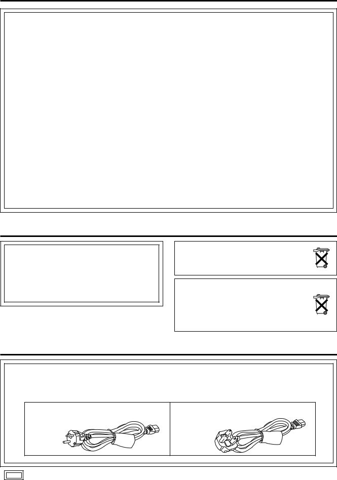
For your safety (when using the LQ-MD800P in Europe)
The LQ-MD800P is equipped with the North American type mains cable only.
When using this product in Europe, you must use a 3-core grounding type of mains cable that complies with the appropriate national standard.
Obtain the following mains cable.
FOR CONTINENTAL EUROPE, ETC. |
FOR U.K. ONLY |
(Part number: VJA0746) |
(Part number: VJA0738) |
is the safety information.
– 4 –
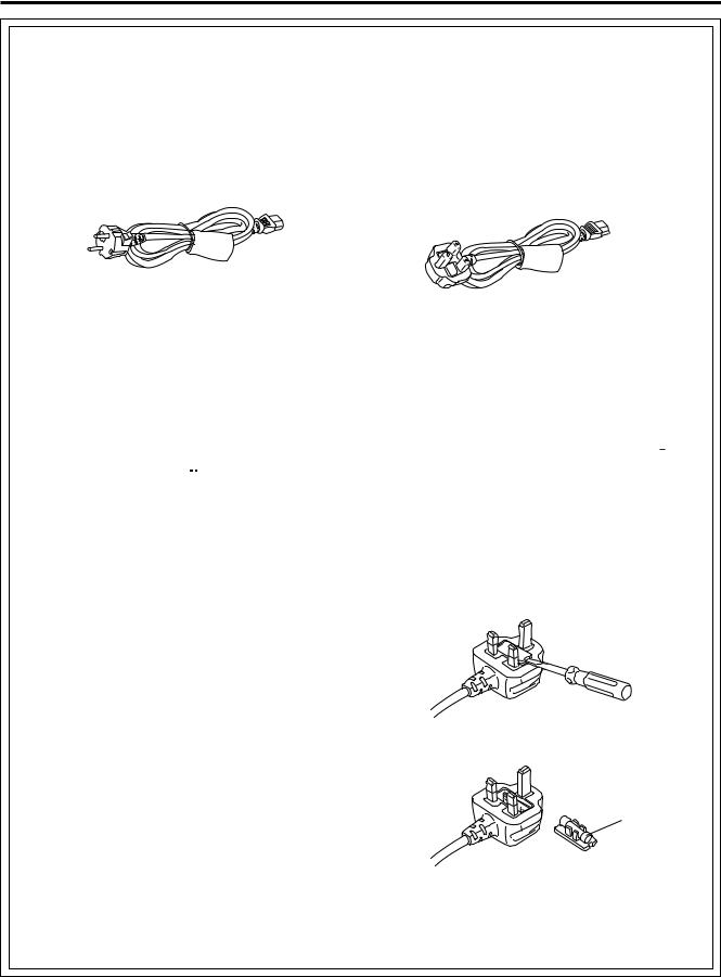
For your safety (when using the LQ-MD800E in Europe)
Caution for AC Mains Lead
FOR YOUR SAFETY PLEASE READ THE FOLLOWING TEXT CAREFULLY.
This product is equipped with 2 types of AC mains cable. One is for continental Europe, etc. and the other one is only for U.K.
Appropriate mains cable must be used in each local area, since the other type of mains cable is not suitable.
FOR CONTINENTAL EUROPE, ETC. |
FOR U.K. ONLY |
Not to be used in the U.K. |
If the plug supplied is not suitable for your socket |
|
outlet, it should be cut off and appropriate one fitted. |
|
|
FOR U.K. ONLY
This appliance is supplied with a moulded three pin mains plug for your safety and convenience.
A 13 amp fuse is fitted in this plug.
Should the fuse need to be replaced please ensure that the replacement fuse has a rating of 13 amps and that it is approved by ASTA or BSI to BS1362.
Check for the ASTA mark  or the BSI mark
  on the body of the fuse.
If the plug contains a removable fuse cover you must ensure that it is refitted when the fuse is replaced.
If you lose the fuse cover the plug must not be used until a replacement cover is obtained.
A replacement fuse cover can be purchased from your local Panasonic Dealer.
IF THE FITTED MOULDED PLUG IS UNSUITABLE FOR THE SOCKET OUTLET IN YOUR HOME THEN THE FUSE SHOULD BE REMOVED AND THE PLUG CUT OFF AND DISPOSED OF SAFELY. THERE IS A DANGER OF SEVERE ELECTRICAL SHOCK IF THE CUT OFF PLUG IS INSERTED INTO ANY 13 AMP SOCKET.
If a new plug is to be fitted please observe the wiring code as shown below.
If in any doubt please consult a qualified electrician. WARNING: THIS APPLIANCE MUST BE EARTHED. IMPORTANT: The wires in this mains lead are coloured in accordance with the following code:
Green-and-Yellow: Earth
Blue: Neutral Brown: Live
As the colours of the wires in the mains lead of this appliance may not correspond with the coloured markings identifying the terminals in your plug, proceed as follows:
•The wire which is coloured GREEN-AND-YELLOW must be connected to the terminal in the plug which is marked with the letter E or by the Earth symbol  or coloured GREEN or GREEN-AND-YELLOW.
•The wire which is coloured BLUE must be connected to the terminal in the plug which is marked with the letter N or coloured BLACK.
•The wire which is coloured BROWN must be connected to the terminal in the plug which is marked with the letter L or coloured RED.
How to replace the fuse
1. Open the fuse compartment with a screwdriver.
2. Replace the fuse.
Fuse
– 5 –

Contents
For your safety ................................................. |
2 |
Features ............................................................ |
7 |
Accessories ..................................................... |
7 |
Control reference guide .................................. |
8 |
• Front Panel ........................................................ |
8 |
• The unit’s display ............................................... |
9 |
• Rear Panel....................................................... |
10 |
Discs ................................................................ |
11 |
Connecting and Setting up............................ |
12 |
Recording programs ..................................... |
16 |
Playing discs ................................................. |
17 |
• Starting play from where you stopped it |
|
(Resume Function) .......................................... |
17 |
• Fast forward and rewind .................................. |
17 |
• Slow-motion play ............................................. |
17 |
• Frame-by-frame viewing .................................. |
17 |
• Skipping ........................................................... |
17 |
• Skip five minutes forward or backward |
|
(Time slip) ....................................................... |
18 |
• Instant repeat play (Instant Repeat) ................ |
18 |
• Marking places to play again (MARKER) ........ |
18 |
Status displays ............................................. |
19 |
• Changing the information displayed ................ |
19 |
• Display examples............................................. |
19 |
Using the FUNCTION menus........................ |
20 |
• Common procedures ....................................... |
20 |
• Disc menu........................................................ |
20 |
• Play menu........................................................ |
21 |
• Sound menu .................................................... |
21 |
• Picture menu.................................................... |
21 |
Using the MENU window .............................. |
22 |
• About the MENU window................................. |
22 |
• Using the MENU window ................................. |
22 |
DISC INFORMATION .................................... |
23 |
• Enter Title ........................................................ |
23 |
• Disc Protection/Releasing disc protection ....... |
23 |
• Erase all programs........................................... |
23 |
• Format ............................................................. |
24 |
• Finalize – Creating DVD-Video........................ |
24 |
Using the SEARCH PROGRAM ..................... |
25 |
• Selecting programs to play .............................. |
25 |
• Erasing programs (Erase)................................ |
26 |
• Entering and editing program titles (Enter Title)...... |
26 |
• Checking program contents (Properties) ......... |
26 |
• Protecting programs/Releasing |
|
program protection (Protection) ....................... |
26 |
• Erasing parts of a program (Partial Erase) ...... |
27 |
• Dividing programs (Divide) .............................. |
27 |
Using the PLAY LIST to edit programs........ |
28 |
• Displaying PLAY LIST ..................................... |
28 |
• Creating PLAY LIST ........................................ |
28 |
• Playing PLAY LIST .......................................... |
29 |
• Playing Scenes (Play Scenes)......................... |
29 |
• Adding Scenes to a PLAY LIST (Add) ............. |
29 |
• Moving a Scene (Move)................................... |
30 |
• To re-edit a PLAY LIST Scene (Re-edit) ......... |
30 |
• Erasing a Scene from a PLAY LIST (Erase).... |
30 |
• Copying PLAY LIST (PL Copy)........................ |
31 |
• Erasing a PLAY LIST (PL Erase)..................... |
31 |
• Titling PLAY LIST (Enter Title)......................... |
31 |
• Checking PLAY LIST’s contents (Properties)...... |
31 |
Entering titles ................................................. |
32 |
Changing the unit’s settings ........................ |
33 |
• Common procedures ....................................... |
33 |
• Summary of settings ........................................ |
33 |
Maintenance and Handling............................ |
36 |
• Maintenance .................................................... |
36 |
• Disc handling ................................................... |
36 |
Glossary .......................................................... |
37 |
Error messages .............................................. |
38 |
Troubleshooting guide................................... |
40 |
Connector signals .......................................... |
42 |
Regarding copyright ...................................... |
42 |
Specifications ................................................. |
43 |
– 6 –

Features
This unit allows recording of high quality video on DVD-RAM, the compact and durable digital media with fast random access. This media also outperforms past tape formats in ease of operation.
 Exceptional sound and picture quality when recording
Audio is recorded using Dolby Digital stereo, enabling high quality sound recordings. When recording in XP/SP mode it is possible to use LPCM (2 channel) to achieve sound recordings of even higher quality.
The MPEG2 encoder system used for recording is called “Hybrid VBR” and allows high quality recordings.
 Maximum 8 hours on DVD-RAM
Using a double sided, 9.4 GB DVD-RAM allows you to record a maximum of 8 hours (4 hours continuously).
 Progressive Scan (see page 13)
By connecting the component video terminals of this unit to a progressive scan monitor television, it is possible to watch the high quality picture rendered by the progressive scan function.
 External control function (see page 14)
This unit has USB, RS-232C, and PAUSE REMOTE terminals to enable remote control from computers or other equipment. Using USB or RS-232C allows you to enter program titles.
 NTSC/PAL switchable (see page 35)
You can play or record NTSC or PAL by changing the settings in TV System in the SETUP menu.
 Fast access to the program you want to
watch RAM DVD-R (see page 25)
Use the SEARCH PROGRAM to find a program you have recorded and start play.
 The MENU window shows you most of the features you can use (see page 22)
The MENU window has most of the features and functions you are likely to use regularly. Just select the icon for the operation you want to perform.
 Editing your recording RAM
(see pages 27 and 28)
You can divide and erase programs.
Use play lists to select scenes you need and rearrange them to play in any order you like.
 Make DVD-Video (see page 24)
Finalizing a DVD-R that has been recorded on produces a DVD-Video in accordance with DVD-Video standards.
 Small and light
The unit’s dimensions are 8-7/16˝(w) x 4-1/32˝(h) x 14- 3/8˝(d) (214 (W) x 102 (H) x 365 (D) mm) and it weighs only 10.14 lbs (4.6 kg).
Accessories
Standard accessories
 Power cord x 1 For USA, Canada (LQ-MD800P) x 2 For Europe (LQ-MD800E)
 Emergency ejection pin x 1
Optional accessories
Part numbers are current as of December 2003. They may change without notice.
 DVD-RAM discs
• 9.4 GB, double-sided, type 4 cartridge:
LM-AD240U (For USA and Canada) LM-AD240E (For Europe)
• 4.7 GB, single-sided, type 2 cartridge:
LM-AB120U (For USA and Canada) LM-AB120E (For Europe)
• 4.7 GB, single-sided, non-cartridge:
LM-AF120U (For USA and Canada) LM-AF120E (For Europe)
 DVD-R discs
• 4.7 GB, single-sided, non-cartridge:
LM-RF120U (For USA and Canada) LM-RF120E (For Europe)
 DVD-RAM/PD Disc cleaner: LF-K200DCA1
 DVD-RAM/PD Lens cleaner: LF-K123LCA1
– 7 –
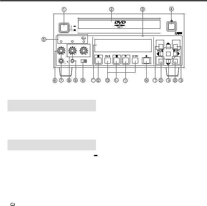
Control reference guide
Front Panel
|
|
|
|
DVD VIDEO RECORDER |
|
|
|
|
|
|
OPEN/CLOSE |
|
|
|
|
|
|
|
|
|
|
|
|
|
|
|
POWER |
|
|
|
|
|
|
|
|
4.7GB |
|
|
|
|
|
|
|
|
|
|
|
|
|
|
|
BUSY |
|
REC |
|
CH1 |
CH2 |
|
|
|
REMAIN |
|
|
|
INHIBIT |
|
|
|
|
|
|
||||||
|
|
|
|
|
|
|
|
|
MENU |
REPEAT FUNCTION |
||
|
|
|
|
|
|
|
|
|
|
|
||
PHONES |
CH1/MIC |
|
CH2 |
|
|
|
|
|
SEARCH |
STATUS |
||
|
|
|
|
|
|
|
|
|||||
|
|
|
|
|
|
|
|
|
|
|
|
MARKER |
MIN |
MAX |
MIN |
MAX |
MIN |
STOP |
REV |
PAUSE |
PLAY |
FWD |
REC |
|
|
MAX |
|
|
|
|
|
|
ENTER RETURN |
|||||
|
|
|
|
MODE LOCK |
|
|
|
|
|
SHIFT |
||
|
|
|
|
OFF |
ON |
|
|
|
|
|
|
|
 POWER on/off button (POWER)
Main power switch. The display lights when the unit is on.
NOTE: Do not switch the unit off during recording, play, or editing.
 Disc tray
Open the try and put a disc on it.
 Emergency ejection hole
Use the included emergency ejection pin to open the tray if you ever need to remove the disc manually (see page 40).
NOTE: Switch the unit off if you need to use the emergency ejection pin to open the tray.
 Disc tray Open/close button (OPEN/CLOSE
  )
)
Press to open when the tray is closed and to close when the tray is open.
 LED’s
LED’s
BUSY |
|
Lights when accessing the disc, as |
|
|
|
when recording or playing. |
|
|
|
|
|
|
|
NOTE: Don't shut off the power supply |
|
|
|
when it lights up. |
|
|
|
|
|
REC INHIBIT |
|
When it is turned on, neither recording |
|
|
|
nor editing is possible. |
|
|
|
|
|
(REPEAT) |
|
Lights while the repeat function is operating. |
|
|
|
|
|
 Headphones level control
Adjust the level of headphones.
 Headphones Jack (Stereo mini jack)
Connect stereo headphones.
 Audio REC level control CH1/MIC, CH2
Adjust the level of audio recording. Cannot adjust the level of the DV IN audio.
 Microphone Jack (mini jack)
Connect a microphone. The microphone signal is recorded in channel 1.
 MODE LOCK
When it is set to ON, none of the front panel switch can be operated.
 Display
Shows various information (see page 9).
 Stop button (STOP
  )
)
Stops recording and play.
 Slow/Search buttons (REV

 , FWD
, FWD 

 )
)
Press during play to start search play. Press while paused to start slow play.
Press while stopped to operate search play at the maximum speed.
 Pause button (PAUSE
 )
)
Pauses play or recording. Releases pause.
 Play button (PLAY
  )
)
Plays the disc.
 Recording button (REC
  )
)
Records video and audio to a disc.
 Search program button (SEARCH)
Press to select a program.
Menu button (MENU [SHIFT + SEARCH])
Press to use menu functions.
 Status button (STATUS)
Press to use the status display function.
Functions button (FUNCTION [SHIFT +STATUS])
Press to use the function menu.
 Cursor buttons (
  ,
,  ,
,  ,
,  )
)
Used to select menu items.
REPEAT button (REPEAT [SHIFT +  ])
])
Press during play to start instant repeat play.
SKIP or STEP button ( 


 ,
, 


 )
)
Press during play to skip items. Press while paused to start step play.
SKIP button (  ,
, 
 [SHIFT +


 ,
, 


 ])
])
Press during play to skip items.
Enter button (ENTER)
Press to confirm selection of menu items.
Marker button (MARKER [SHIFT + ENTER])
Press to set a marker.
 RETURN button (RETURN)
Press to cancel selection of menu items.
 Shift buttons (SHIFT)
Press together with other buttons to use blue-labeled functions.
– 8 –
Control reference guide (continued)
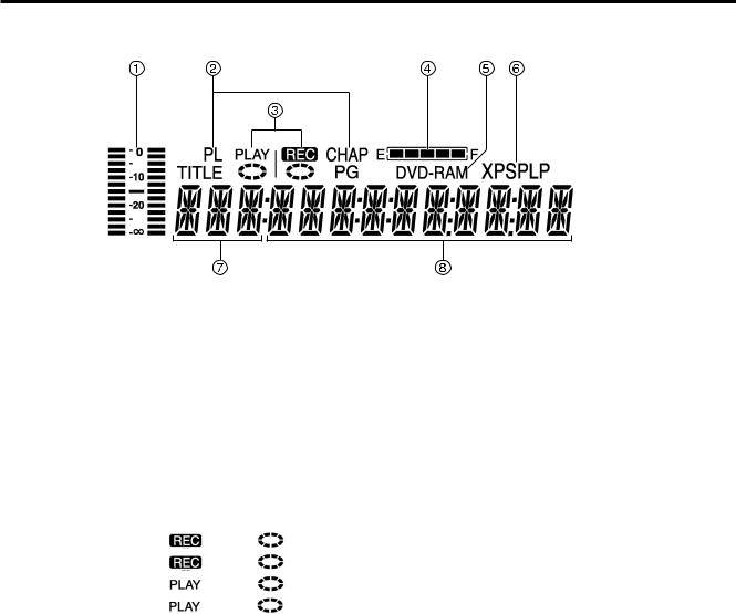
The unit’s display
 Audio Level Meter
Shows the recording level. Adjust the recording level with Audio REC level control CH1/MIC, CH2 on the front panel so that the level meter does not exceed 0 dB.
 The display mode of the main display section
Shows disc structure. TITLE : Title number
CHAP : Chapter number PG : Program number PL : Play list number
 REC/PLAY Indication
Shows play or recording status.
Recording: |
lighting |
rotating |
Recording paused: |
lighting |
stopped |
Playing: |
lighting |
rotating |
Play paused: |
lighting |
stopped |
 Remain
“REMAIN” provides rough indication of the disc remaining amount. Each lamp goes off one after another according to the decrease of the disc remaining amount.  This is not an exact indication of the disc remaining
amount.
 Disc type
Shows the type of disc.
DVD-RAM : DVD-RAM
DVD-R : DVD-R
DVD : Finalized DVD-R
 Recording mode
Shows recording mode.
XP : High-quality mode
SP : Normal mode
LP : Long play mode
 Input
Input
Shows video input.
V : Video
SV : S-Video
DV : DV IN
 Main display section
Shows various types of information.
•Recording and play counter
•Remaining recording time
(For example: 1 hour → Displayed as “R 1:00”)
•Current time
•Title, Chapter, Group
•Miscellaneous messages
etc.
– 9 –

Control reference guide (continued)
Rear Panel
VIDEO |
|
VIDEO IN |
|
|
~ AC IN |
|
|
|
|
S-VIDEO |
|
|
|
Y |
PB |
PR |
|
|
|
|
VIDEO |
|
VIDEO OUT |
|
|
|
|
1 |
|
|
S-VIDEO |
|
|
|
|
|
|
|
|
||
|
CH1(A) |
CH2(B) |
CH1 |
CH2 |
|
|
2 |
|
|
|
|
|
|
|
AUDIO IN |
AUDIO OUT |
AUDIO |
|
||
DV IN PAUSE |
MON |
USB |
||||
|
|
|
|
RS-232C |
||
REMOTE |
|
|
|
|
|
|
 VIDEO IN (BNC)
Composite signal input.
 VIDEO OUT 1/2 (BNC)
Composite signal output.
 Y, PB, PR (Component Video output) (BNC)
Component signal (Y, PB, PR) output.
 S-VIDEO IN (4P)
S-Video (Y/C) input.
 S-VIDEO OUT (4P)
S-Video (Y/C) output.
 Equipotential terminal
When connecting this unit to any other component, make absolutely sure that it is properly grounded by connecting this terminal.
When connecting, use the socket and be sure to use wire with a cross-sectional area of at least 1.0 mm2.
Cross-sectional area :
Socket
More than 1.0 mm2
 Power socket
Connect power cord (supplied).
 DV IN (4-pin)
DV input. Connect a 4-pin IEEE1394 cable. You can digitally input video and audio.
 PAUSE REMOTE (Stereo mini jack)
External control jack for recording start and pause control. This jack also outputs a recording status signal.
 Audio CH1 (A)/CH2 (B) input connector (PHONO)
Input for analog audio. If you have connected a microphone, use the Audio CH assignment with Mic setting in the SETUP menus to assign recording channels.
 Security Lock
This can be used to connect a commercially-available theft-prevention cable (manufactured by Kensington). This security lock is compatible with the Microsaver Security System from Kensington.
 Audio CH1/CH2 output connector (PHONO)
Analog audio output.
 Audio Monitor output connector (PHONO)
Analog audio output. Use the Monitor setting item in the FUNCTION menus to assign the channel to be output.
 RS-232C Remote connector (D-sub 9P)
RS-232C terminal. Connect a computer or other control device to enable external control.
 USB Remote connector (Type-B connector)
USB terminal. Connect a computer or other control device to enable external control.
– 10 –
Discs
We recommend using discs manufactured by Panasonic as they have been tested to be compatible with this unit. In case of discs manufactured by other makers, play may be impossible in some cases due to the condition of the recording.
Disc type |
Logo |
Indication used |
Recording |
Playing |
Creation of |
Configuration examples of data on a disc |
|||||
in instructions |
PLAY LIST |
||||||||||
DVD-RAM |
|
RAM |
Yes |
Yes |
Yes |
Programs |
1 |
2 |
3 |
4 |
5 |
|
|
|
|
|
|
|
|||||
• 4.7 GB/ 9.4 GB (12 cm) |
|
PLAY LIST |
Scene1 Scene2 Scene3 Scene4 Scene5 |
||||||||
|
|
|
|
|
|||||||
|
|
|
|
|
|
||||||
|
|
|
|
|
|
|
|
|
|
|
|
DVD-R |
|
Before finalizing |
Yes |
Yes |
No |
Programs |
1 |
2 |
3 |
4 |
5 |
• 4.7 GB (12 cm) |
|
DVD-R |
|||||||||
|
|
|
|
|
|
||||||
for General Ver. 2.0 |
|
|
|
|
|
|
|
|
|
|
|
|
|
|
|
|
|
|
|
|
|
|
|
• 4.7 GB (12 cm) |
|
After finalizing |
|
|
|
Titles |
|
1 |
|
|
2 |
for General |
|
No |
Yes |
No |
|
|
|
||||
Ver.2.0/4x-Speed |
|
DVD |
Chapters |
1 |
2 |
3 |
4 |
5 |
|||
DVD-R Revision 1.0 |
|
|
|
|
|
|
|
|
|
||
The manufacturer accepts no responsibility and offers no compensation for loss of recorded or edited material due to a problem with the unit or disc, and accepts no responsibility and offers no compensation for any subsequent damage caused by such loss.
Examples of causes of such losses are
(1)A disc recorded and edited with this unit is played in a DVD recorder or computer disc drive manufactured by another company.
(2)A disc used as described in (1) and then played again in this unit.
(3)A disc recorded and edited with a DVD recorder or computer disc drive manufactured by another company is played in this unit.
Notes:
•This unit is compatible with the Content Protection for Recordable Media (CPRM) system so you can record broadcasts that allow one copy, such as some CATV broadcasts, onto 4.7 GB/9.4 GB DVD-RAM (these are CPRM compatible). It is not possible to record onto DVD-R.
•Do not allow the disc to become dirty or scratched. Fingerprints, dirt, dust, and scratches on the recording surface may make it impossible to use the disc for recording.
•If you use DVD-RAM cartridges, you can protect your recordings with the write protected tab. With the tab in this position, you cannot record to the disc, delete programs with the search program, edit with the play list screen, or format the disc.
•This unit is compatible with both non-cartridge and cartridge DVD-RAM, but cartridge-type discs give better protection to your valuable recordings.
For your reference:
•DVD-RAM recorded on this unit cannot be played on incompatible players (including players manufactured by Panasonic).
•This unit cannot record PAL signals to discs containing NTSC signals or vice versa.
•This unit cannot record to discs containing both PAL and NTSC signals.
Play of discs recorded with both PAL and NTSC on another unit is not guaranteed.
•Do not perform editing operations, such as finalizing, if the TV system of the unit and disc are different.
unit if it was recorded with another unit, whether it is finalized or not. You cannot record over parts that have been recorded. Erasing programs will not increase the disc’s available time.
•It may not be possible for you to perform finalizing and other editing operations normally if you perform actions such as deleting programs or changing titles a total of 200 times on the same disc.
 After finalizing
The video and audio is recorded according to the DVD-Video specifications.
•The titles you entered with this unit appear as menus.
•Programs longer than 5 minutes are divided into approximately-5-minute chapters.
•These DVD-R can no longer be recorded on or edited.
•These DVD-R can be played on other DVD players, but this is not guaranteed. Play may not be possible due to the player you are using, the DVD-R, or the condition of the recording. Use this unit to play the disc if the player is unable.
For your reference:
•The aspect ratio of recordings will be 4:3, irrespective of the aspect ratio of the program recorded. To change the aspect ratio, change the setting on the monitor television.
•It takes about 30 seconds for the unit to complete recording management information after recording finishes.
•To record on DVD-R, this unit optimizes the disc for each recording.
Optimizing is carried out when you start recording after inserting the disc or turning the unit on. Recording may become impossible after the disc is optimized more than 50 times.
•Play may be impossible in some cases due to the condition of the recording.
•We recommend using DVD-R manufactured by Panasonic as they have been tested to be compatible with this unit.
•You cannot change audio type if a DVD-R is in the unit. Select the audio type (M1 or M2) before recording by going to “Bilingual Audio Selection” in the “Sound” menu.
•A DVD-R recorded on this unit may not be recordable on other Panasonic DVD recorders.
Examples of discs that cannot be played
DVD-Video, DVD-Audio, Some DVD-R, DVD-RAM (2.6 GB/5.2 GB), 8cm DVD-R, 8cm DVD-RAM (2.8 GB), DVD-ROM, DVD-RW, +RW, CD-ROM, Audio-CDs, Video-CD, CDV, CD-G, CVD, SVCD, SACD, MV-Disc, PD, Photo CD, Divx Video Disc, etc.
Regarding DVD-R
You can play DVD-R on compatible DVD players by finalizing (the process that allows recordings on DVD-R to be played on compatible DVD players) them on this unit, effectively making them into DVD-Video.
 Before finalizing
•You can record onto the available space on the disc and perform editing functions, such as giving titles to discs and programs and erasing programs. You cannot record to or edit DVD-R with this
Audio format logos
 Dolby Digital
This unit can play Dolby Digital in stereo (2 channels).
Manufactured under license from Dolby Laboratories.
“Dolby” and double-D symbol are trademarks of Dolby Laboratories.
– 11 –
Discs (continued)
Types of disc for the type of connected monitor television
When you use the discs recorded either PAL or NTSC, refer to this table. If you select the same TV system (PAL or NTSC) setting for this unit and your monitor television as the disc you want to play, the picture can be clearer.
Type of monitor television |
TV system |
Yes/No |
|
on discs. |
|
|
|
|
Multi system monitor |
NTSC |
Yes |
|
|
|
television |
PAL |
Yes |
|
|
|
NTSC monitor television |
NTSC |
Yes |
|
|
|
|
PAL |
No |
PAL monitor television |
NTSC |
Yes*1 (PAL60) |
|
PAL |
Yes*2 |
 You may be unable to use same functions or they may function incorrectly if the TV system for the unit is different to that for the disc.
*1 If your monitor television is not equipped to handle PAL 525/60 signals the picture will not be shown correctly.
*2 If you set the TV system of this unit to “PAL”, the picture may be clearer.
Connecting and Setting up
Put the unit on a stable, horizontal surface where it will not be exposed to excessive dust. Do not block its vents or place where it can become hot.
First of all, please disconnect AC mains leads of all units, which you are going to connect with before connecting and disconnecting cables. Reconnect the AC mains leads when all connections are complete. Read the instructions for the other units carefully.
Audio/video input will not be output if this unit is switched off or malfunctions. Consider other connections in the system when outputting audio/video for the purpose of monitoring input. To record essential material, use multiple units to record at the same time, or make other similar allowances in your system setup.
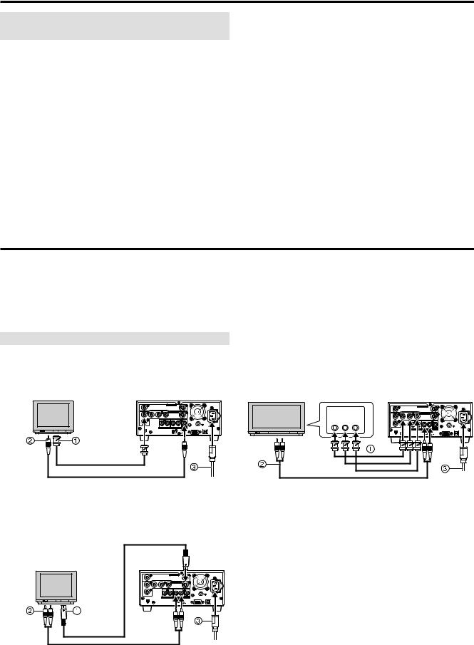
Connecting a Monitor television
 Composite video, monaural audio terminals
 Video cable (BNC)
 Audio cable (PHONO)
  AC mains lead (supplied)
VIDEO |
|
VIDEO IN |
|
|
~ AC IN |
|
|
|
|
S-VIDEO |
|
|
|
Y |
P |
P |
|
|
|
|
VIDEO |
|
VIDEO OUT |
|
|
|
|
1 |
|
|
S-VIDEO |
|
|
|
|
CH1(A) |
CH2(B) |
CH1 |
CH2 |
|
|
PAUSE |
AUDIO IN |
AUDIO OUT |
RS-232C |
USB |
||
REMOTE |
|
|
|
|
|
|
AUDIO |
VIDEO |
VIDEO |
AUDIO |
|
IN |
IN |
OUT |
||
MONO |
||||
|
|
|
||
|
|
|
OUT |
 Component video terminals
 Component video (BNC x 3)
 Stereo Audio cable (PHONO x 2)
 AC mains lead (supplied)
COMPONENT |
VIDEO |
|
VIDEO IN |
~ AC IN |
|
Y |
P |
P |
S-VIDEO |
|
|
VIDEO IN |
VIDEO |
|
VIDEO OUT |
|
|
1 |
|
|
S-VIDEO |
|
|
Y PB PR |
2 |
CH1(A) |
CH2(B) |
CH1 CH2 |
|
|
|
|
|
AUDIO |
|
|
DV IN PAUSE |
AUDIO IN |
AUDIO OUT MON RS-232C |
USB |
|
REMOTE
AUDIO |
AUDIO |
IN |
OUT |
 S-Video, stereo audio terminals
 S-Video cable (4P)
 Stereo Audio cable (PHONO x 2)
  AC mains lead (supplied)
AUDIO S-VIDEO
IN IN
S-VIDEO |
|
|
|
||
|
OUT |
|
|
|
|
VIDEO |
|
VIDEO IN |
|
|
~ AC IN |
|
|
S-VIDEO |
|
|
|
Y |
P |
P |
|
|
|
VIDEO |
|
VIDEO OUT |
|
|
|
1 |
|
S-VIDEO |
|
|
|
|
CH1(A) |
CH2(B) CH1 |
CH2 |
|
|
2 |
|
|
|
|
|
|
AUDIO IN |
AUDIO |
|
|
|
DV IN PAUSE |
MON |
RS-232C |
USB |
||
REMOTE |
|
|
|
|
|
AUDIO |
|
|
|
||
OUT |
|
|
|
||
To set to progressive output mode
(1)While stopped, press [MENU (SHIFT + SEARCH) ] to show the MENU window.
(2)Use [  ,
,  ,
,  ,
,  ] to select the “SETUP” and press [ENTER].
(3)Use [  ,
,  ] to select the “Connection” and press [
  ] or [
  ].
].
(4)Use [  ,
,  ] to select “TV System” and press [ENTER].
(5)Use [  ,
,  ] to select “NTSC” and press [ENTER].
(6)Use [  ,
,  ] to select “Progressive (NTSC)” and press [ENTER].
(7)Use [  ,
,  ] to select “On” and press [ENTER].
To return to the previous screen
Press [RETURN].
– 12 –

Connecting and Setting up (continued)
COMPONENT VIDEO OUT terminal
These terminals can be used for either interlace or progressive output and provide a purer picture than the S-VIDEO OUT terminal.
Connection using these terminals outputs the color difference signals (PB/PR) and luminance signal (Y) separately in order to achieve high fidelity in reproducing colors.
•The description of the component video input terminals depends on the monitor television (e.g., Y/PB/PR, Y/B-Y/R-Y, Y/CB/CR).
To watch progressive video (NTSC only)
Connect to the component video (480P) input terminals on a monitor television compatible with this unit's copy guard system. (Video will not be displayed correctly if connected to an incompatible monitor television.)
•All Panasonic monitor televisions that have 480P input terminals are compatible. Consult the manufacturer if you have another brand of monitor television.
Regarding Progressive Television Picture
Progressive image aspect (height to width ratio) is set at a standard 16:9. DVD-Video which has been set at 16:9 will be displayed correctly. However, 4:3 video material will be stretched to the right and left when displayed.
To view the picture at the right aspect
•For monitor televisions that allow the aspect of progressive images to be adjusted, use the function provided on the monitor television and adjust as necessary.
•For monitor televisions which do not allow the aspect of progressive images to be adjusted, please set “Progressive (NTSC)” to “Off”.
Note:
•If the unit is connected to the TV through VIDEO OUT or S- VIDEO OUT, output signal will be interlace only (even if you select progressive output).
Connecting a video player
 Composite video, stereo audio terminals
 Video cable (BNC)
 Stereo Audio cable (PHONO x 2)
  AC mains lead (supplied)
|
|
VIDEO |
|
|
|
|
IN |
|
|
Video player |
|
S-VIDEO |
|
|
|
|
|
VIDEO IN |
~ AC IN |
|
|
Y P |
P |
|
|
|
VIDEO |
VIDEO OUT |
|
|
|
1 |
S-VIDEO |
|
|
|
CH1(A) |
CH2(B) CH1 CH2 |
|
|
|
2 |
|
|
|
|
|
AUDIO |
|
|
|
DV IN PAUSE |
AUDIO OUT MON RS-232C |
USB |
|
|
REMOTE |
|
|
AUDIO |
|
|
|
|
OUT |
VIDEO |
AUDIO IN |
|
|
|
|
|
||
|
OUT |
|
|
|
|
|
|
|
|
 S-Video, stereo audio terminals
 S-Video cable (4P)
 Stereo Audio cable (PHONO x 2)
 AC mains lead (supplied)
|
|
S-VIDEO |
|
|
|
|
|
IN |
|
Video player |
VIDEO |
VIDEO IN |
~ AC IN |
|
|
|
|
S-VIDEO |
|
|
|
Y P |
P |
|
|
|
VIDEO |
VIDEO OUT |
|
|
|
1 |
S-VIDEO |
|
|
|
CH1(A) |
CH2(B) CH1 CH2 |
|
|
|
2 |
|
|
|
|
|
AUDIO |
|
|
|
DV IN PAUSE |
AUDIO OUT MON RS-232C |
USB |
AUDIO |
|
REMOTE |
|
|
S-VIDEO |
|
|
|
|
OUT |
|
|
|
|
OUT |
AUDIO IN |
|
|
|
|
|
|
||
 DV terminal
 DV cable (4P-4P or 4P-6P)
 AC mains lead (supplied)
Video player
VIDEO |
|
VIDEO IN |
|
|
|
~ AC IN |
|
|
|
|
S-VIDEO |
|
|
|
|
Y |
P |
P |
|
|
|
|
|
VIDEO |
|
VIDEO OUT |
|
|
|
|
|
1 |
|
|
S-VIDEO |
|
|
|
|
|
CH1(A) |
CH2(B) |
CH1 |
CH2 |
|
|
|
2 |
|
|
|
|
|
|
|
|
AUDIO IN |
AUDIO OUT |
AUDIO |
|
|
||
DV IN PAUSE |
MON |
RS-232C |
USB |
||||
REMOTE
DV OUT
DV IN
Notes:
•Be sure to observe the following points when connecting the IEEE1394 cable (DV cable).
·This unit and all connected equipment should be used with a shared GND connection. If all equipment is not connected to a shared GND, turn off the power to all equipment before connecting or removing the IEEE1394 cable.
·When connecting to equipment having a 6-pin terminal, connect the IEEE1394 cable to the 6-pin terminal first and then to the terminal on this unit.
·When connecting to equipment having a 6-pin terminal, be sure to connect the end of the IEEE1394 cable that matches the terminal shape. Inserting the wrong end of the plug can damage the unit.
•The DV input on this unit is for use with DV equipment only.
•When DV equipment is connected, it is not possible to operate the unit from the other equipment.
•Only one piece of DV equipment (e.g., Digital Video Camera) can be connected to the unit via the DV Input terminal.
•The picture compression system of the DV equipment you have connected may differ from that used in this unit. In such cases, dubbing from this equipment will not be possible.
– 13 –
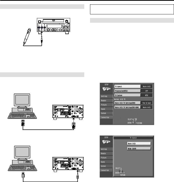
Connecting and Setting up (continued)
Connecting a Microphone
If you record while a microphone is connected, microphone signal can be recorded in channel 1.
|
|
|
|
DVD VIDEO RECORDER |
|
|
|
|
|
|
OPEN/CLOSE |
|
|
|
|
|
|
|
|
|
|
|
|
|
|
|
POWER |
|
|
|
|
|
|
|
|
4.7GB |
|
|
|
|
|
|
|
|
|
|
|
|
|
|
|
BUSY |
|
REC |
|
CH1 |
CH2 |
|
|
|
REMAIN |
|
|
|
INHIBIT |
|
|
|
|
|
|
||||||
|
|
|
|
|
|
|
|
|
|
|
MENU |
REPEAT FUNCTION |
PHONES |
CH1/MIC |
|
CH2 |
|
|
|
|
|
SEARCH |
STATUS |
||
|
|
|
|
|
|
|
|
|||||
|
|
|
|
|
|
|
|
|
|
|
|
MARKER |
MIN |
MAX |
MIN |
MAX |
MIN |
STOP |
REV |
PAUSE |
PLAY |
FWD |
REC |
|
|
MAX |
|
|
|
|
|
|
ENTER RETURN |
|||||
|
|
|
|
MODE LOCK |
|
|
|
|
|
SHIFT |
||
|
|
|
|
OFF |
ON |
|
|
|
|
|
|
|
MIC
Notes:
•When a microphone is connected, the sound recorded to channel 2 is that selected in “Audio CH assignment with Mic”.
•Use a microphone with the monaural mini plug. When using a condenser microphone, select the one with built-in batteries.
Connecting a PC
Various controls are available if you connect a computer through the RS-232C or USB terminals.
 RS-232C terminal
VIDEO |
|
VIDEO IN |
|
|
|
~ AC IN |
|
|
|
|
S-VIDEO |
|
|
|
|
Y |
P |
P |
|
|
|
|
|
VIDEO |
|
VIDEO OUT |
|
|
|
|
|
1 |
|
|
S-VIDEO |
|
|
|
|
|
CH1(A) |
CH2(B) |
CH1 |
CH2 |
|
|
|
2 |
|
|
|
|
|
|
|
|
AUDIO IN |
AUDIO OUT |
AUDIO |
|
|
||
DV IN PAUSE |
MON |
RS-232C |
USB |
||||
REMOTE
RS-232C
RS-232C cable (9P straight)
 USB terminal
VIDEO |
|
VIDEO IN |
|
|
|
~ AC IN |
|
|
|
|
S-VIDEO |
|
|
|
|
Y |
P |
P |
|
|
|
|
|
VIDEO |
|
VIDEO OUT |
|
|
|
|
|
1 |
|
|
S-VIDEO |
|
|
|
|
|
CH1(A) |
CH2(B) |
CH1 |
CH2 |
|
|
|
2 |
|
|
|
|
|
|
|
|
AUDIO IN |
AUDIO OUT |
AUDIO |
|
|
||
DV IN PAUSE |
MON |
RS-232C |
USB |
||||
REMOTE
|
USB cable |
USB |
|
|
|
Type-A |
|
Type-B |
connector |
|
connector |
Use the following procedures to change the settings if necessary. For other items, see page 33.
TV screen type (TV Aspect)
The aspect ratio is factory set to 4:3 for a regular monitor television. You do not have to change this setting if you have a regular 4:3 aspect monitor television.
(1)Turn on the monitor television and select the appropriate video input to suit the connections to this unit.
(2)While stopped, press [MENU (SHIFT + SEARCH) ] to show the MENU window.
(3)Use [  ,
,  ,
,  ,
,  ] to select the “SETUP” and press [ENTER].
(4)Use [  ,
,  ] to select the “Connection” and press [
  ] or [
  ].
].
(5)Use [  ,
,  ] to select “TV Aspect” and press [ENTER].
(6)Use [  ,
,  ] to select the TV aspect and press [ENTER].
• 4:3 (factory setting)
• 16:9
 To return to the previous screen
Press [RETURN].
For your reference:
Apart from “TV Aspect”, other settings also affect how video appears on your monitor television. Check the following if video doesn’t appear correctly on your monitor television.
•“Connection”–“Norm (4:3) TV Settings (DVD)” or “Norm (4:3) TV Settings (DVD-RAM)”.
•The video setting on the disc.
How video appears is often specified by the disc itself.
•The video settings on your monitor television.
– 14 –
Loading...