


LP-V10U
Table of contents
 Loading...
6th
6
Preface
R
Thank you for purchasing Laser Marker "LP-V series, LP-W series".
For full use of this laser marker safely and properly, please read this manual carefully.
This system has been strictly checked and tested prior to its delivery, however, please make sure that this system operates properly before using it.
In case that the system becomes damaged or does not operate as specified in this manual, contact the shop
you bought it or our sales agency.
Symbol Indications
This manual uses a variety of symbols to explain safety precautions, instructions, and references for operating
personnel.
Before reading this manual, fully understand the contents of these indications.
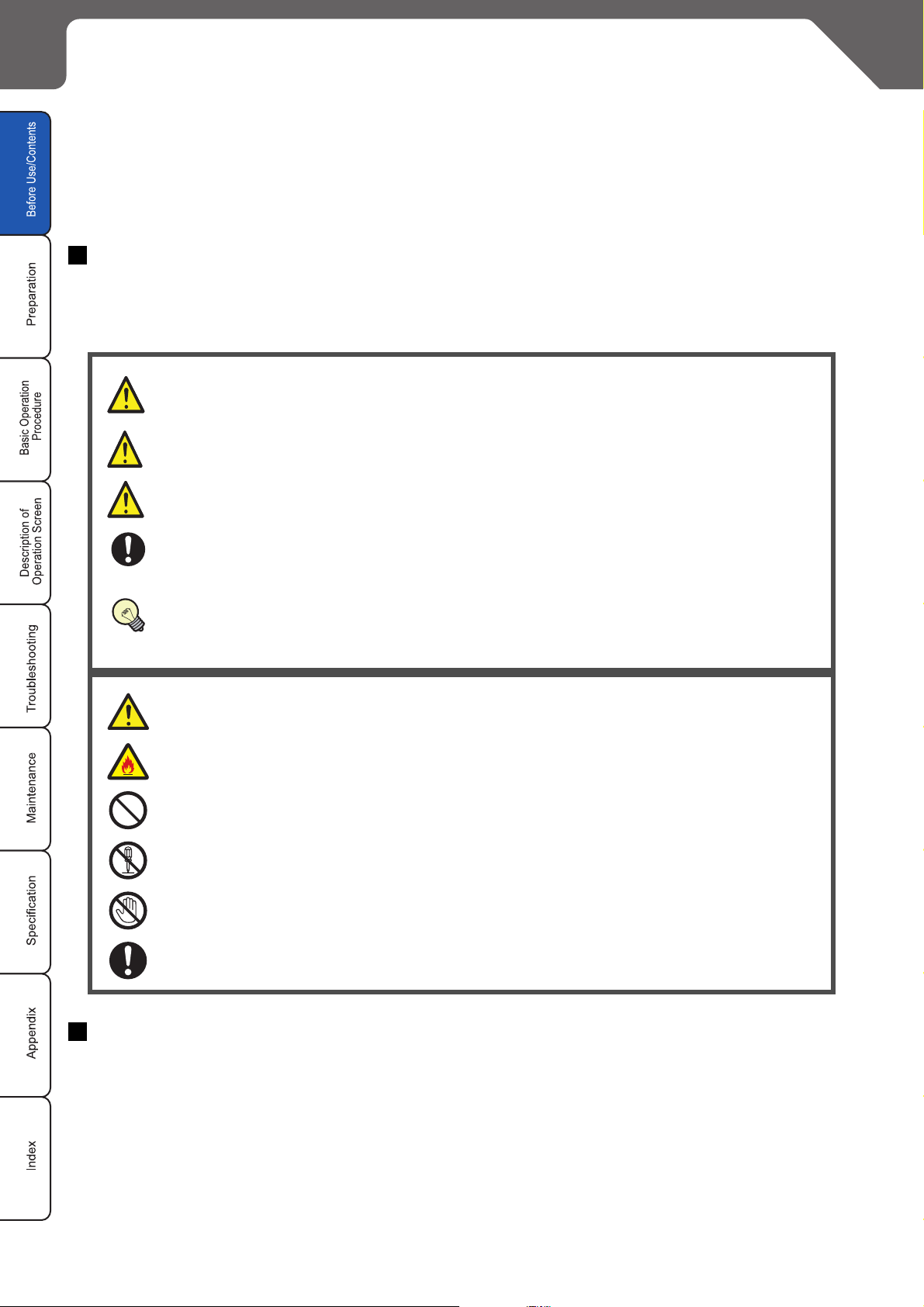
"DANGER" denotes hazards that could result in serious personnel injury or death
DANGE
WARNING
when handling error occurs, and emergency precautions (urgency level) when any
dangerous situation causes.
"WARNING" denotes hazards that could result in serious personnel injury or death
when handling error occurs.
CAUTION
CHECK
REFERENCE
"CAUTION" denotes that any damages on personnels or objects could result in when
handling error occurs.
"CHECK" denotes any instructions or precautions for using this system.
"REFERENCE" denotes any hints for operation, detail explanations, or references.
This symbol denotes that the contents gives notice of the above "DANGER" and
"CAUTION" to operators. Read and keep the contents carefully.
This symbol denotes the possibility of fire.
This symbol denotes a general prohibition notice.
This symbol denotes the prohibition of disassembling the product.
This symbol denotes the prohibition of touching the specified place.
This symbol denotes a general action which operators must take.
Note
1. This manual is subject to LP-V series and LP-W series. This manual uses LP-V series’ illustrations and
screens. Therefore, please notice that illustrations might be little different between these two models.
2. Before using this product, or before every starting operation, please confirm the correct functioning and
performance of this product.
3. Contents of this manual will be changed without notice. This manual and software must not be partially or
totally copied or revised.
4. If there are any questions, mistakes, or comments in this manual, please notify us.
5. Please remind that we have not responsibility of any results of operations in regardless of the above 3
clause.
2 Preface
Before Use
Trademarks
Window XP is a registered trademark or trademark of U.S.A. Microsoft Corporation in U.S.A and other
countries.
All other product names and companies provided in this manual are trademarks or registered trademarks
of their respective companies.
QR Code is a registered trademark of DENSO WAVE INCORPORATED.
Warranty of Product
1. Warranty Period
The warranty period is one year after delivery of the system to the ordered place by a purchaser.
2. Warranty Limitation
When a failure is produced by a supplier, exchange of the failure parts of the system, or repair of it is
performed in the responsibility of the supplier.
However, if failure of the system has resulted from the following reasons, the warranty is void.
1) Any fault or defect caused by inadequate handling or abnormal use.
2) Any fault or defect caused by the other reasons than the supplier's fault.
3) Any fault or defect caused by modification or repair of the system by any others than the suppliers.
4) Any fault or defect caused by acts of God or force majeure.
Note that the warranties set forth herein cover faults of defects of delivered products alone and do not
cover any damage induced by faults or defects of delivered products.
■ Adaptation Model
LP-V/W series has various models shown in the below list. Please confirm their adaptation types.
Model Standard (JIS Standard compliant) -A (FDA standard compliant)
LP-V10U
LP-V15U
LP-W052U
Note:
1. In this manual, “-A” just after the model number of laser marker indicates that the model is FDA-compliant.
○○
○○
○○
Preface 3

License Agreement
• You have acquired a device (“DEVICE”) that includes software licensed by “SUNX Limited” from an affiliate of Microsoft Corporation (“MS”). Those installed software
products of MS origin, as well as associated media, printed materials, and “online” or electronic documentation (“SOFTWARE”) are protected by international intellectual
property laws and treaties. Manufacturer, MS and its suppliers (including Microsoft Corporation) own the title, copyright, and other intellectual property rights in the
SOFTWARE. The SOFTWARE is licensed, not sold. All rights reserved.
• This EULA is valid and grants the end-user rights ONLY if the SOFTWARE is genuine and a genuine Certificate of Authenticity for the SOFTWARE is included. For more
information on identifying whether your software is genuine, please see http://www.microsoft.com/piracy/howtotell.
• IF YOU DO NOT AGREE TO THIS END USER LICENSE AGREEMENT (“EULA”), DO NOT USE THE DEVICE OR COPY THE SOFTWARE. INSTEAD, PROMPTLY
CONTACT “SUNX Limited” FOR INSTRUCTIONS ON RETURN OF THE UNUSED DEVICE(S) FOR A REFUND. ANY USE OF THE SOFTWARE, INCLUDING BUT
NOT LIMITED TO USE ON THE DEVICE, WILL CONSTITUTE YOUR AGREEMENT TO THIS EULA (OR RATIFICATION OF ANY PREVIOUS CONSENT).
• GRANT OF SOFTWARE LICENSE. This EULA grants you the following license:
1 You may use the SOFTWARE only on the DEVICE.
2 RESTRICTED FUNCTIONALITY. You are licensed to use the SOFTWARE to provide only the limited functionality (specific tasks or processes) for which
the DEVICE has been designed and marketed by “SUNX Limited”. This license specifically prohibits any other use of the SOFTWARE programs or
functions, or inclusion of additional software programs or functions that do not directly support the limited functionality on the DEVICE. Notwithstanding the
foregoing, you may install or enable on the DEVICE systems utilities, resource management or similar software solely for the purpose of administration,
performance enhancement and/or preventive maintenance of the DEVICE.
3 If you use the DEVICE to access or utilize the services or functionality of Microsoft Windows Server products (such as Microsoft Windows Server 2003), or
use the DEVICE to permit workstation or computing devices to access or utilize the services or functionality of Microsoft Windows Server products, you may
be required to obtain a Client Access License for the DEVICE and/or each such workstation or computing device. Please refer to the end user license
agreement for your Microsoft Windows Server product for additional information.
4 NOT FAULT TOLERANT. THE SOFTWARE IS NOT FAULT TOLERANT. “SUNX Limited” HAS INDEPENDENTLY DETERMINED HOW TO USE THE
SOFTWARE IN THE DEVICE, AND MS HAS RELIED UPON “SUNX Limited” TO CONDUCT SUFFICIENT TESTING TO DETERMINE THAT THE
SOFTWARE IS SUITABLE FOR SUCH USE.
5 NO WARRANTIES FOR THE SOFTWARE. THE SOFTWARE is provided “AS IS” and with all faults. THE ENTIRE RISK AS TO SATISFACTORY
QUALITY, PERFORMANCE, ACCURACY, AND EFFORT (INCLUDING LACK OF NEGLIGENCE) IS WITH YOU. ALSO, THERE IS NO WARRANTY
AGAINST INTERFERENCE WITH YOUR ENJOYMENT OF THE SOFTWARE OR AGAINST INFRINGEMENT. IF YOU HAVE RECEIVED ANY
WARRANTIES REGARDING THE DEVICE OR THE SOFTWARE, THOSE WARRANTIES DO NOT ORIGINATE FROM, AND ARE NOT BINDING ON,
MS.
6 No Liability for Certain Damages. EXCEPT AS PROHIBITED BY LAW, MS SHALL HAVE NO LIABILITY FOR ANY INDIRECT, SPECIAL,
CONSEQUENTIAL OR INCIDENTAL DAMAGES ARISING FROM OR IN CONNECTION WITH THE USE OR PERFORMANCE OF THE SOFTWARE.
THIS LIMITATION SHALL APPLY EVEN IF ANY REMEDY FAILS OF ITS ESSENTIAL PURPOSE. IN NO EVENT SHALL MS BE LIABLE FOR ANY
AMOUNT IN EXCESS OF U.S. TWO HUNDRED FIFTY DOLLARS (U.S.$250.00).
7 Restricted Uses. The SOFTWARE is not designed or intended for use or resale in hazardous environments requiring fail-safe performance, such as in the
operation of nuclear facilities, aircraft navigation or communication systems, air traffic control, or other devices or systems in which a malfunction of the
SOFTWARE would result in foreseeable risk of injury or death to the operator of the device or system, or to others.
8 Limitations on Reverse Engineering, Decompilation, and Disassembly. You may not reverse engineer, decompile, or disassemble the SOFTWARE,
except and only to the extent that such activity is expressly permitted by applicable law notwithstanding this limitation.
9 SOFTWARE as a Component of the DEVICE - Transfer. This license may not be shared, transferred to or used concurrently on different computers. The
SOFTWARE is licensed with the DEVICE as a single integrated product and may only be used with the DEVICE. If the SOFTWARE is not accompanied by
a DEVICE, you may not use the SOFTWARE. You may permanently transfer all of your rights under this EULA only as part of a permanent sale or transfer
of the DEVICE, provided you retain no copies of the SOFTWARE. If the SOFTWARE is an upgrade, any transfer must also include all prior versions of the
SOFTWARE. This transfer must also include the Certificate of Authenticity label. The transfer may not be an indirect transfer, such as a consignment. Prior
to the transfer, the end user receiving the SOFTWARE must agree to all the EULA terms.
10 Consent to Use of Data. You agree that MS, Microsoft Corporation and their affiliates may collect and use technical information gathered in any manner
as part of product support services related to the SOFTWARE. MS, Microsoft Corporation and their affiliates may use this information solely to improve
their products or to provide customized services or technologies to you. MS, Microsoft Corporation and their affiliates may disclose this information to
others, but not in a form that personally identifies you.
11 Internet Gaming/Update Features. If the SOFTWARE provides, and you choose to utilize, the Internet gaming or update features within the SOFTWARE,
it is necessary to use certain computer system, hardware, and software information to implement the features. By using these features, you explicitly
authorize MS, Microsoft Corporation and/or their designated agent to use this information solely to improve their products or to provide customized services
or technologies to you. MS or Microsoft Corporation may disclose this information to others, but not in a form that personally identifies you.
12 Internet-Based Services Components. The SOFTWARE may contain components that enable and facilitate the use of certain Internet-based services.
You acknowledge and agree that MS, Microsoft Corporation or their affiliates may automatically check the version of the SOFTWARE and/or its
components that you are utilizing and may provide upgrades or supplements to the SOFTWARE that may be automatically downloaded to your DEVICE.
Microsoft Corporation or their affiliates do not use these features to collect any information that will be used to identify you or contact you. For more
information about these features, please see the privacy statement at http://go.microsoft.com/fwlink/?LinkId=25243.
13 Links to Third Party Sites. You may link to third party sites through the use of the SOFTWARE. The third party sites are not under the control of MS or
Microsoft Corporation, and MS or Microsoft are not responsible for the contents of any third party sites, any links contained in third party sites, or any
changes or updates to third party sites. MS or Microsoft Corporation is not responsible for webcasting or any other form of transmission received from any
third party sites. MS or Microsoft Corporation are providing these links to third party sites to you only as a convenience, and the inclusion of any link does
not imply an endorsement by MS or Microsoft Corporation of the third party site.
14 Notice Regarding Security. To help protect against breaches of security and malicious software, periodically back up your data and system information,
use security features such as firewalls, and install and use security updates.
15 No Rental/Commercial Hosting. You may not rent, lease, lend or provide commercial hosting services with the SOFTWARE to others.
16 Separation of Components. The SOFTWARE is licensed as a single product. Its component parts may not be separated for use on more than one
computer.
17 Additional Software/Services. This EULA applies to updates, supplements, add-on components, product support services, or Internet-based services
components (“Supplemental Components”), of the SOFTWARE that you may obtain from “SUNX Limited”, MS, Microsoft Corporation or their subsidiaries
after the date you obtain your initial copy of the SOFTWARE, unless you accept updated terms or another agreement governs. If
provided along with such Supplemental Components and the Supplemental Components are provided to you by MS, Microsoft Corporation or their
subsidiaries then you will be licensed by such entity under the same terms and conditions of this EULA, except that (i) MS, Microsoft Corporation or their
subsidiaries providing the Supplemental Components will be the licensor with respect to such Supplemental Components in lieu of the "COMPANY" for the
purposes of the EULA, and (ii) TO THE MAXIMUM EXTENT PERMITTED BY APPLICABLE LAW, THE SUPPLEMENTAL COMPONENTS AND ANY (IF
ANY) SUPPORT SERVICES RELATED TO THE SUPPLEMENTAL COMPONENTS ARE PROVIDED AS IS AND WITH ALL FAULTS. ALL OTHER
DISCLAIMERS, LIMITATION OF DAMAGES, AND SPECIAL PROVISIONS PROVIDED BELOW AND/OR OTHERWISE WITH THE SOFTWARE SHALL
APPLY TO SUCH SUPPLEMENTAL COMPONENTS. MS, Microsoft Corporation or their subsidiaries reserve the right to discontinue any Internet-based
services provided to you or made available to you through the use of the SOFTWARE.
18 Recovery Media. If SOFTWARE is provided by “SUNX Limited” on separate media and labeled “Recovery Media” you may use the Recovery Media solely
to restore or reinstall the SOFTWARE originally installed on the DEVICE.
19 Backup Copy. You may make one (1) backup copy of the SOFTWARE. You may use this backup copy solely for your archival purposes and to reinstall
the SOFTWARE on the DEVICE. Except as expressly provided in this EULA or by local law, you may not otherwise make copies of the SOFTWARE,
including the printed materials accompanying the SOFTWARE. You may not loan, rent, lend or otherwise transfer the backup copy to another user.
20 End User Proof of License. If you acquired the SOFTWARE on a DEVICE, or on a compact disc or other media, a genuine Microsoft “Proof of License”/
Certificate of Authenticity label with a genuine copy of the SOFTWARE identifies a licensed copy of the SOFTWARE. To be valid, the label must be affixed
to the DEVICE, or appear on “SUNX Limited’s” software packaging. If you receive the label separately other than from “SUNX Limited”, it is invalid. You
should keep the label on the DEVICE or packaging to prove that you are licensed to use the SOFTWARE.
21 Product Support. Product support for the SOFTWARE is not provided by MS, Microsoft Corporation, or their affiliates or subsidiaries. For product
support, please refer to “SUNX Limited” support number provided in the documentation for the DEVICE. Should you have any questions concerning this
EULA, or if you desire to contact “SUNX Limited” for any other reason, please refer to the address provided in the documentation for the DEVICE.
22 Termination. Without prejudice to any other rights, “SUNX Limited” may terminate this EULA if you fail to comply with the terms and conditions of this
EULA. In such event, you must destroy all copies of the SOFTWARE and all of its component parts.
EXPORT RESTRICTIONS. You acknowledge that SOFTWARE is subject to U.S. and European Union export jurisdiction. You agree to comply with all appli-
cable international and national laws that apply to the SOFTWARE, including the U.S. Export Administration Regulations, as well as end-user, end-use
and destination restrictions issued by U.S. and other governments. For additional information see http://www.microsoft.com/exporting/.
other terms are not
4 Preface

MEMO
Before Use
Preface 5
Caution in Handling Laser Beam
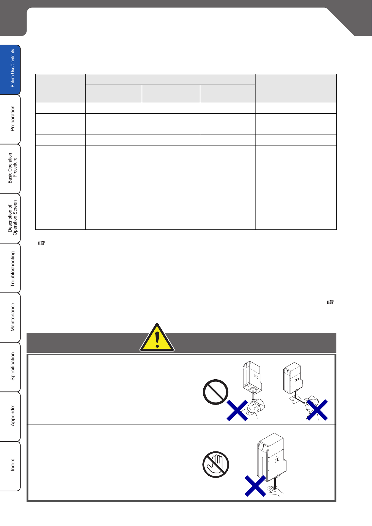
The system uses invisible fiber laser beam with maximum output of 15W (LP-V10U. LP-V15U)/7.5W (LPW052U) and wave length of 1060nm.
The laser used here corresponds to the Class 4 according to "Safety of laser products" in JIS C 6802, IEC60825-1.
Specification
Item
Wave length 1060nm Invisible beam
Laser Medium Yb: FIBER Max. Output 15W 7.5W Pulse Cycle 10 to 50µs--
LP-V10U,
V10U-A
LP-V15U,
V15U-A
LP-W052U,
W052U-A
Remarks
Class
NOHD Approx. 38.0m Approx.69.5m Approx. 36.5m
NHZ represents the area where the amount of beam irradiance or radiant expposure exceeds the maximum permissible exposure to eyes. It is equal to the value of NOHD at a
NHZ
Refer to Laser Radiation Information (also refer to the attachment of this manual "Radiation Information"
( P.318) for more details).
The “CLASS 4 LASER PRODUCT” refers to
maximum.
NHZ varies depending on the reflectance or surface condition of works. Please calculate it based on the actual working environment.
4
Nominal optical
hazarddistance
Nominal hazard area
-
"a product which may cause injury to a human if exposed to its directly radiated
light, even it is reflecting light and diffused refle
cting light, or which may produce a risk of a fire.
Perform the safety prevention measure before using the system. Refer to "Safety Protection Measures" (
P.8) for details.
Never look at laser beam directly or
through lens.
Diffused reflected beam is also harmful.
Fiber laser does not enter into eye's retina,
however, if it exposed to the eyes, it can
inflict severe corneal injuries.
Avoid human skin exposure directly to laser
beam. Burning into deep skin might result.
6 Caution in Handling Laser Beam
DANGER
WARNING
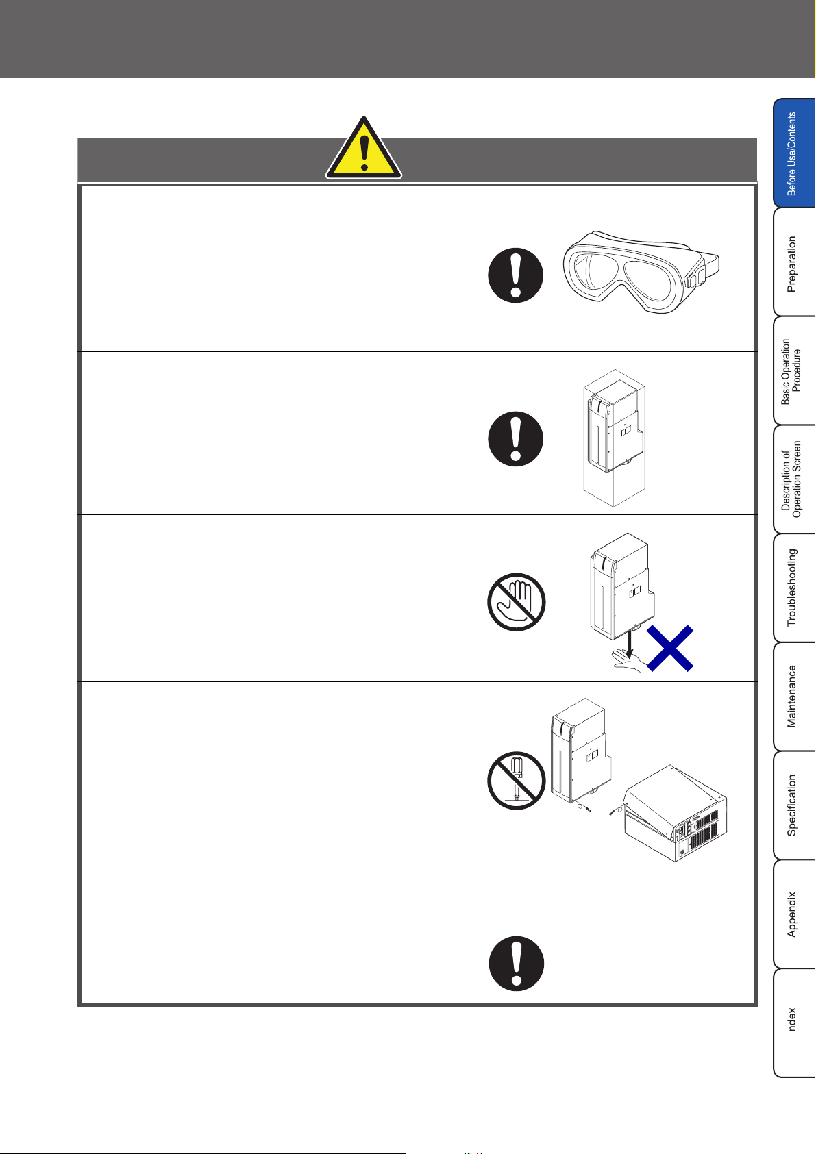
Wear laser protective goggles for operator's
eyes. The goggles should be used against
scattered beam, so avoid to direct beam or
reflection beam. (Do not look laser beam during guide indication even when laser pumping
switch is turned off.)
In order to prevent unexpected exposures from
object to be marked or its peripherals, set protective enclosure which is made of acrylic resin,
glass, or metal to enclose the laser radiation
Before Use
.
area
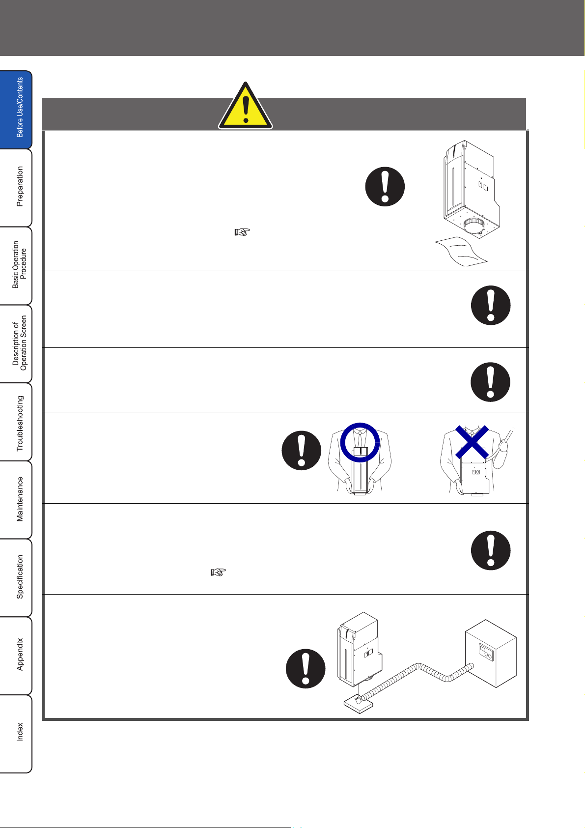
Never touch laser beam.
Be careful not to touch laser beam with
clothing as well.
When using the system, do not touch laser beam with human
body, papers, or clothing, etc.
Never disassemble the product.
Exposure of laser beam or electric shock by high-voltage area
might occur.
Read this manual thoroughly, and do not operate any other methods except
the instructions provided in this manual.
Exposure of laser beam might occur.
Caution in Handling Laser Beam 7
Safety Protection Measures
In the "PART1040 PERFORMANCE STANDARDS FOR LIGHT-EMITTING PRODUCTS" of FDA, safety
prevention measures to be taken by any user of laser products are stipulated. In order for you to use the
system safety, working environment is shown below for your references.
1. Wearing protective goggles
For protection of eyes of an operator, make it mandatory to wear goggles against laser beam.
(Recommendation)
Manufacturer: Yamamoto Optics Co., Ltd. (Japan)
Model: YL-120H Nd-YAG
2. Protective enclosure
In order to prevent exposure to laser beam accidentally reflected from the substrate to be marked or from its
circumferential areas, place a protective enclosure so that it can enclose the area in the range of laser radiation.
The material of the enclosure shall not transmit the 1060nm-wavelength beam at all. (We recommend the following metals for applying the enclosure; iron, aluminum, SUS, etc.)
3. Interlock system
Construct an interlock mechanism in the system.
Provide doors used for taking out products or for maintenance attached to the protection enclosure with functions
of stopping laser radiation whenever a door is opened.
This interlock system is the counterpart of “remote interlock” regulated in JIS C 6802.
4. Power failure recovery
When power failure occurs on the laser marker, construct a laser re-pumping system by manual operation for
safety.
5. Radiation direction of laser beam
To assure safety, be sure to place the protective enclosure. Measures should be taken so that the direction of
laser radiation can be seen and checked by others as well as an operator. (Labels of cautions, instructions,
and open indication are adhered to the system at delivery from the plant. Do not peel them off.)
6. Termination of laser beam
High output laser is used for marking taking into consideration a case where there is no substrate in a laser
path, terminate a laser beam path within the marking range by using a flame-resistant object.
7. Path of laser beam
It is recommended that laser beam passes through the position being either lower than eye-level at the time of
human's sitting or being higher than eye-level at the time of human's standing.
8. Illumination
Make the area surrounding the laser marker well-lighted as much as possible. Because the peoples are contracted
in the well-lit place, your eyes can be well protected.
Do not expose strong beam to the laser radiation exit. Failure to do so could cause the malfuction of the
power check monitor.
9. Protective clothing
Exposure of the skin to the laser beam may cause a skin burn. Exposure of the clothing to the laser beam
may cause burning as well. Wear the clothing which can minimize the exposure of the skin to the laser and
which is flame-resistant.
8 Safety Protection Measures
10. Appointment of laser safety manager
By appointing a laser safety manager, ensure that the laser product is handled safely.
Items that the laser safety manager has to manage and execute are as follows:
A. Storage of laser system
B. Designation of users for the laser product and execution of education and training
C. Designation of controlled zone
D. Maintenance of facilities and fixtures installed within controlled zone
E. Establishment of procedures for operations of the laser system
Establishment of procedures for safety management and installation of warning markings and their execution
F.
G. Keeping and management of key switch
H. Execution of periodical inspection
Refer to the laser safety precautions in ANSI Z136.1-1993, "American National Standard for Safe
Use of Lasers". Procedures listed under the Standard include the appointment of a Laser Safety
Manager, operation of the product in an area of limited access by trained personnel, servicing of
REFERENCE
REFERENCE
equipment only by trained and authorized personnel, and posting of signs warning of the potential
hazards.
The safety measures are described above based on the "Safety of laser products" (JIS C 6802,
IEC60825-1). In addition to these measures, Ministry of Health, Labor and Welfare issued the
aviso ("Protection Measures against Affection by Laser Beam" (No. 39 Aviso by Ministry of Labor
dated January 27, 1986), and defines the detail cautions for using laser beam aiming for
publicizing the cautions as best one can. Besides, the many relative articles for the protection
from operators from the laser beam are dealt with in various regulations such as Industrial Safety
and Health Law, Ordinance on Labor Safety and Hygiene, Air Pollution Control Law. etc.
Before Use
Safety Protection Measures 9
Functions for Safety Measures
This laser marker has the functions shown below for safety measures.
Head Section
2
1
+08+5+$.'.#5'44#&+#6+10
#81+&';'145-+0':21574'61
&+4'%6145%#66'4'&4#&+#6+10
;D(+$'4.#5'42WNUGFWTCVKQP㨚U
9CXGNGPIVJPO/CZKOWOQWVRWV9
.#5'4&+1&'2WNUGFWTCVKQP%9
9CXGNGPIVJPO/CZKOWOQWVRWVO9
%.#55.#5'4241&7%6
+08+5+$.'.#5'44#&+#6+10+5
#81+&
'/+66'&(41/6*+5#2'4674'
':21574'
4
%.#55.#5'4241&7%6
%QORNKGUYKVJ%(4CPF
570:.KOKVGF
7UJK[COC-CUWICK#KEJK,CRCP
/#07(#%674'&
5'4+#.01
�)'4
+08+5+$.'.#5'44#&+#6+109*'012'0
#81+&';'145-+0':21574'61&+4'%6145%#66'4'&4#&+#6+10
3
5
1 Automatic Shutter
Automatic shutter locates inside the head and protects laser beam by closing the inside shutter.
2 Laser Radiation Indicator
The operations of the laser radiation indicator are as follows:
Blue lighted-up : Being in laser pumped state and automatic shutter being closed
Purple lighted-up
Red lighted-up
: Being in laser pumped state and automatic shutter being opened
: Being in laser emitting
2
During pumping of laser (approx. 20sec for LP-V10U/V15U, approx. 15sec for LP-W052U), the
laser radiation indicator flashes in blue or purple according to the automatic shutter state (open
or close).
REFERENCE
When the system is in the starting state, if a laser is not in the pumped state, the laser radiation
indicator goes off.
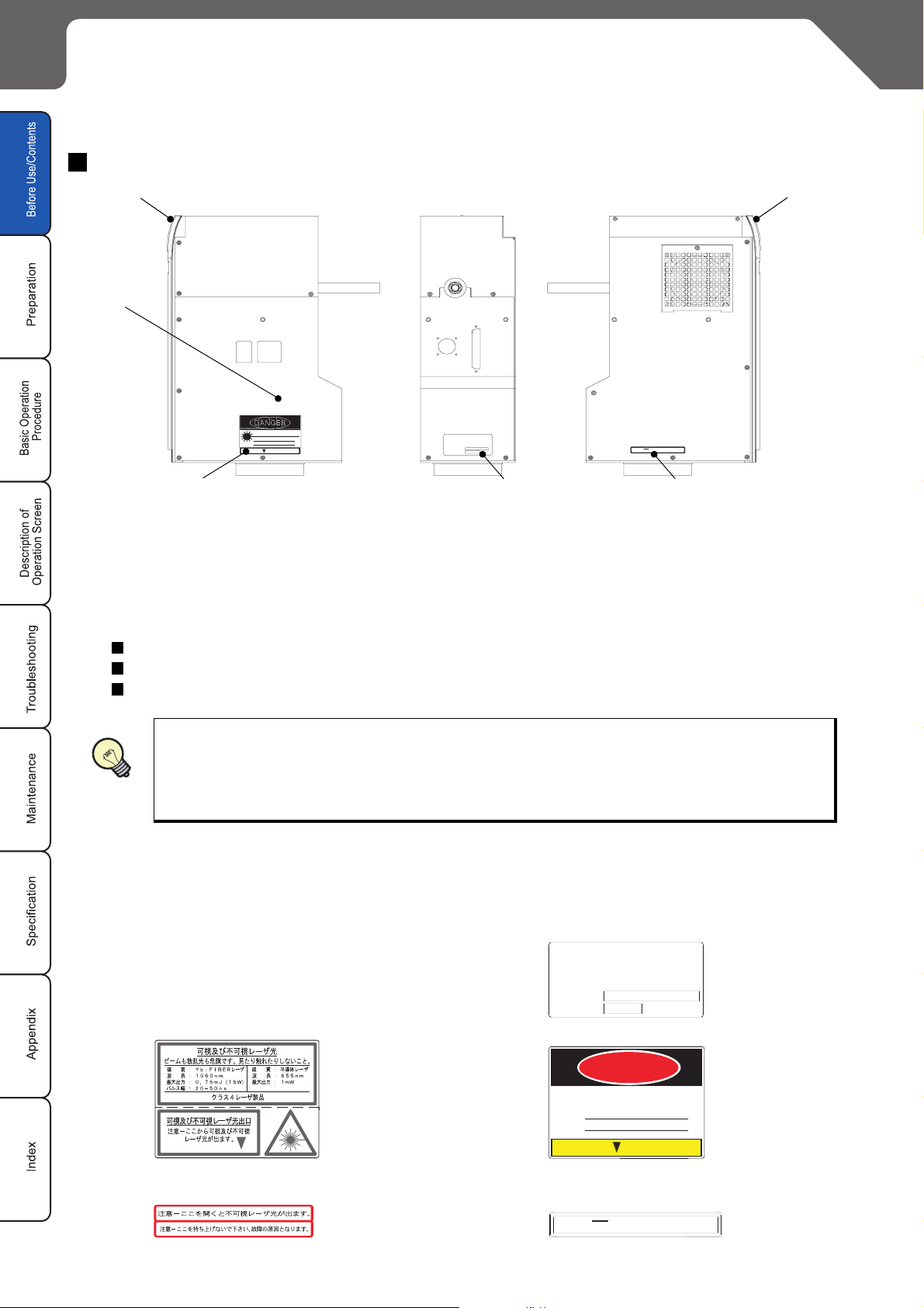
3, 4, 5 Labels
A variety of labels shown below are affixed to the head part of the laser marker.
LP-V10U, LP-V15U, LP-W052U
(The content are differed depending
on the model type.)
4. Warning Logotype, Aperture Label
5. Label for Non-Interlocked Protective Housing
LP-V10U-A, LP-V15U-A, LP-W052U-A
3. Certification and Identification Label
%QORNKGUYKVJ%(4CPF
/#07(#%674'&
4. Warning Logotype, Aperture Label
5. Label for Non-Interlocked Protective Housing
%.#55.#5'4241&7%6
570:.KOKVGF
7UJK[COCEJQ-CUWICKUJK#KEJKMGP,CRCP
5'4+#.01
DANGER
+08+5+$.'.#5'44#&+#6+10
#81+&';'145-+0':21574'61
;D(+$'4.#5'42WNUGFWTCVKQP㨚U
9CXGNGPIVJPO/CZKOWOQWVRWV9
.#5'4&+1&'2WNUGFWTCVKQP%9
9CXGNGPIVJPO/CZKOWOQWVRWVO9
%.#55.#5'4241&7%6
+08+5+$.'.#5'44#&+#6+10+5
#81+&
':21574'
'/+66'&(41/6*+5#2'4674'
10 Functions for Safety Measures
�)'4
+08+5+$.'.#5'44#&+#6+109*'012'0
#81+&';'145-+0':21574'61&+4'%6145%#66'4'&4#&+#6+10

Controller
LP
-
1
series
V
FAYb LASER MARKER
Before Use
2
POWER
7
3
4
8
5
6
1. Key Switch: POWER
This key switch is used to start the laser marker system. Turn On ( l ) the switch to start-up the system,
and turn Off (O) the switch to shutdown the system.
While the switch is ON, the key cannot be removed, however, while it is OFF, the key can be removed.
When the laser marker is not used, remove the key, and the safety controller must keep it.
Since the ON/OFF operation of the key switch makes a load to the laser marker, leave an interval for at least 5
seconds from turning OFF the power to turning ON the power again. Do not turn off the power supply while
the system starts (during the system start indicator is flashing).
2. Emergency Stop Switch: EMERGENCY STOP
This switch is used to forcibly stop the laser pumping.
Push this switch at emergency or to stop the laser radiation. Turn the switch to the direction of the arrow to
release it.
3. Main Power Indicator (Green): MAIN
This indicator flashes when key switch is turned on, and it switches to light-up state when the system
starts.
4. Laser Radiation Indicator (Red): MARKING
This indicator lights up while laser radiation is under operation.
5. Laser Pumping Switch (with White LED): LASER
This switch starts laser pumping.
LED flashes (approx. 20sec for LP-V10U/V15U, approx. 15sec for LP-W052U) in white when the switch is
pressed, and it lights up when the laser irradiation becomes enabled.
6. Remote Switch (with White LED): REMOTE
This switch enables remote mode. LED lights up in white when this remote switch is pressed.
7. File No./Error Code Indicator: FILE No./ERROR CODE
Selected file number is displayed. When an error occurs, its error code is displayed as well.
For the action when an error code is displayed, refer to "4-2 Error Indication” ( P.
298).
8. Alarm Reset Switch (with Blue LED): ALARM RESET
This switch is used to reset the system when an alarm generates. LED lights up in blue when an alarm
generates. Release the cause of alarm and press this switch. Alarm reset can also be performed from terminal block, console (option), or monitor screen.
Functions for Safety Measures 11
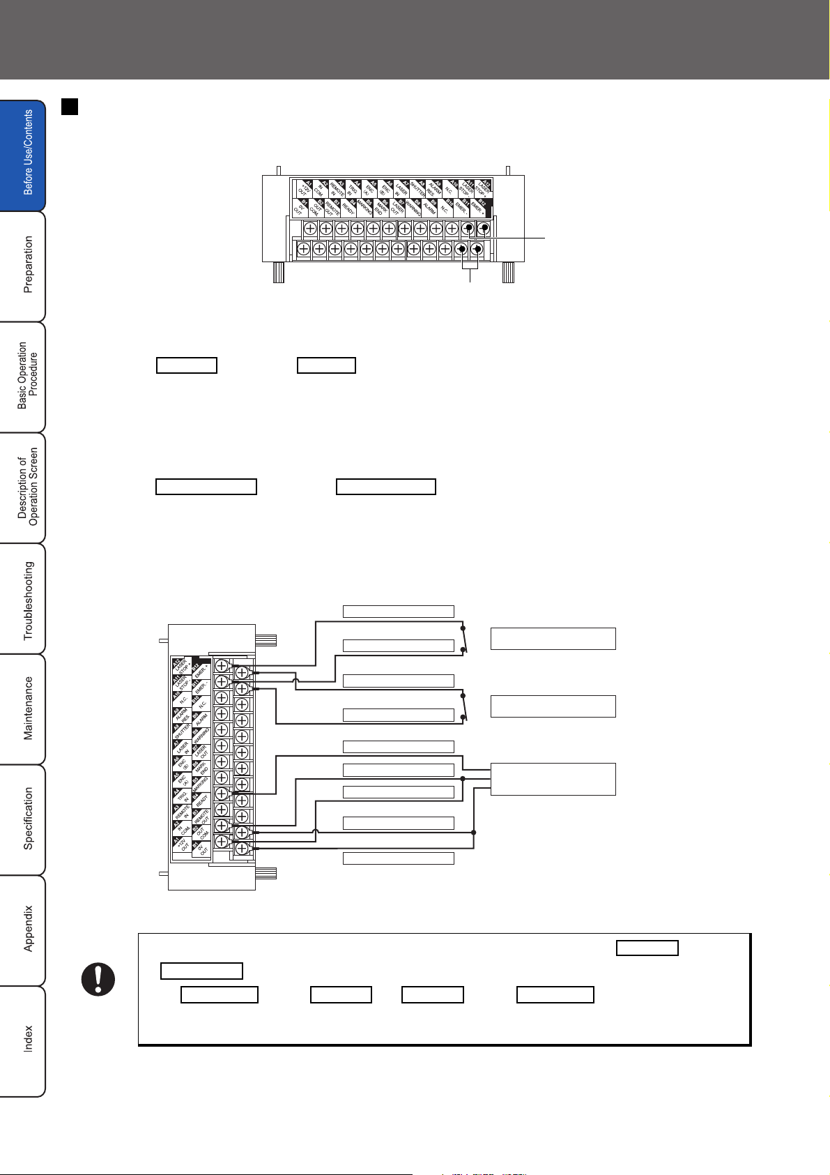
Terminal Block
The system has an emergency stop input and laser stop input on the terminal block.
2
1
1. Emergency Stop Input
Power supply is turned off by opening the emergency stop input (B12) and the emergency stop 0V (B11).
Connect of B12 and of B11 for starting marking.
(B12 and B11 are short-circuited by a short bar at delivery.)
2. Laser Stop Input
Automatic shutter in the head is closed and laser radiation is shut-off by opening the laser stop input (A12)
and the laser stop 0V (A11).
Connect
(A12 and A11 are short-circuited by a short bar at delivery.)
EMER. + EMER. -
LASER STOP
of A12 and
+
LASER STOP
of A11 for starting marking.
-
Connection Sample (In case of operating only laser marker)
LP-V10U, LP-V10U-A, LP-V15U, LP-V15U-A, LP-W052U, LP-W052U-A
A12: LASER STOP +
To Manual Door
To Emergency Stop Switch
To Sensor
CHECK
A11: LASER STOP -
B12: EMER.+
B11: EMER.-
A4 : TRIG.IN
A2 : IN COM.
A1 : +12V OUT
B2 : OUT COM.
B1 : 0V OUT
Connect power supply (internal power and outside power) to A2 and B2
.
OUT COM
+12V OUT
A1 and A2
short bar at delivery.
When using outside power supply, make sure to perform wiring after removing the short bar.
to operates the laser marker.
0V OUT OUT COM
IN COM.
, B1 and B2 are short-circuited by a
IN COM.
.
12 Functions for Safety Measures
Before Use
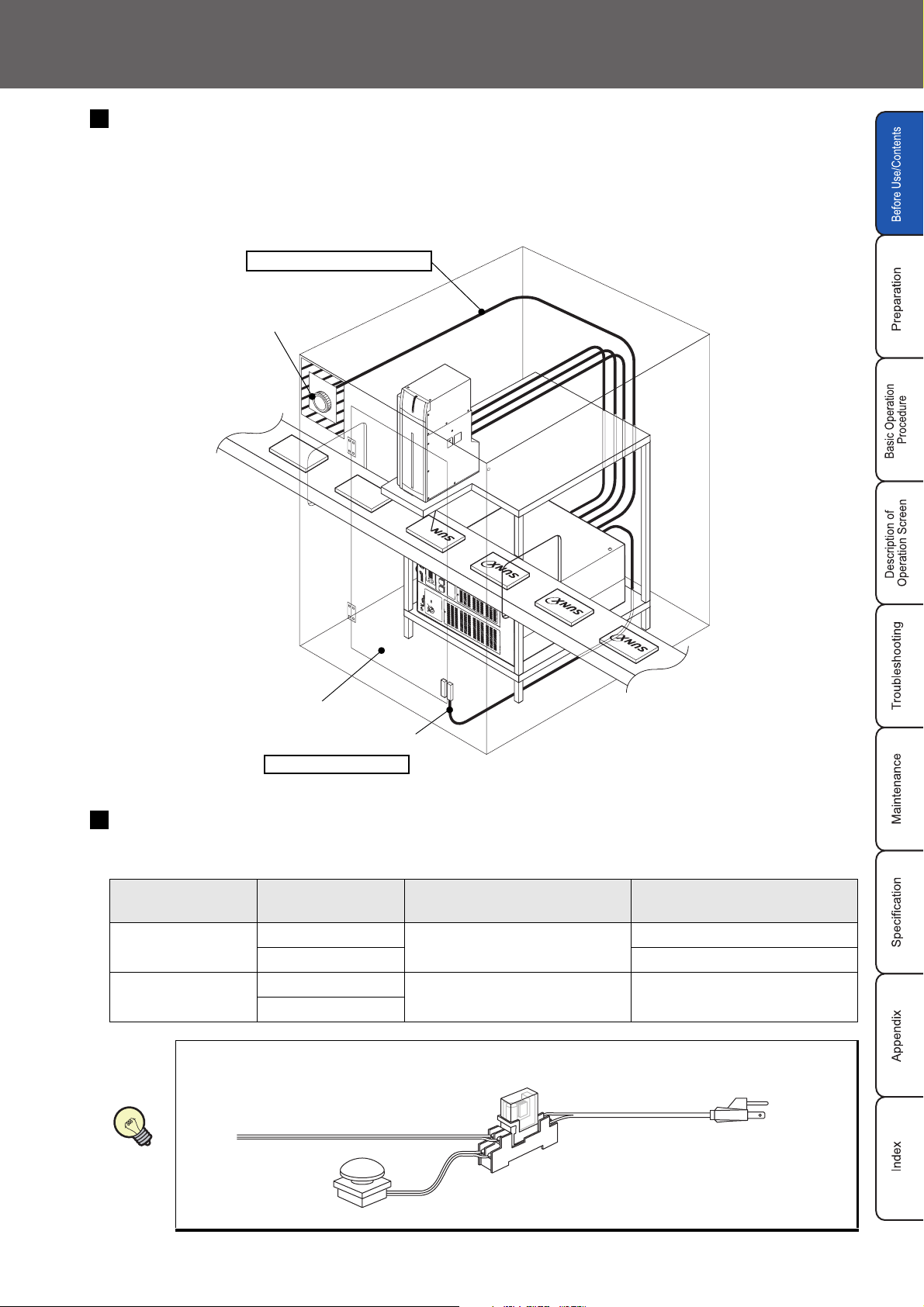
Construction of Interlock System
For operating this product, construct the protective enclosure enclosing the range of the laser radiation for
protecting the exposure caused by the reflection of the laser radiation from the object being marked or the surrounding objects, and also construct the interlock system at the same time. The following figure shows the
construction sample of the interlock system.
Controller Terminal Block
To Emergency Stop Input
Emergency Stop Button
Emergency Stop
Manual Door
Controller Terminal Block
To Laser Stop Input
Emergency Stop Input/Laser Stop Input Operation
When the emergency stop input or the laser stop input is opened, the automatic shutter operates as follows:
Laser Power
Supply
Automatic Shutter
When primary AC power supply of the system is performed as a safety measure, process AC
power cable to set the switch as follows.
AC Power Cable
Marking Status
In marking
In non-marking ON (Keeps pumping)
In marking
In non-marking
Emergency Stop Input
OPEN
OFF
Closed Closed
Laser Stop Input
OPEN
OFF
REFERENCE
Emergency Stop
Switch
Relay
Functions for Safety Measures 13
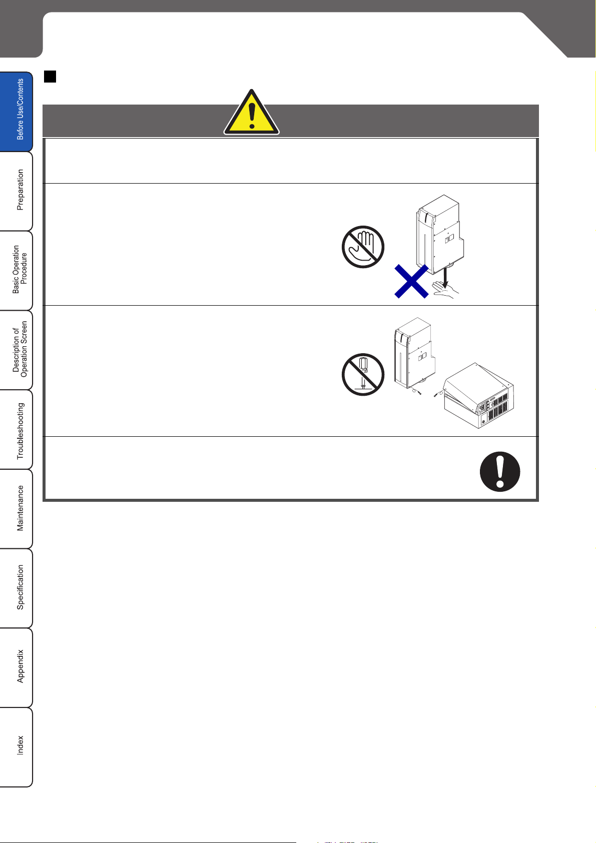
Cautions in Handling
Handling the System
WARNING
This product is developed and manufactured for the purpose of using in
industrial environment.
When using the system, do not touch laser
beam with any part of body, papers, or clothing, etc
Never disassemble the product. It can result
in exposure to laser radiation or an electric
shock due to high voltage.
In the event a failure occurs in the system, contact us.
.
After the power supply of laser marker is turned off, laser safety
manager must remove key and keep it.
14 Cautions in Handling
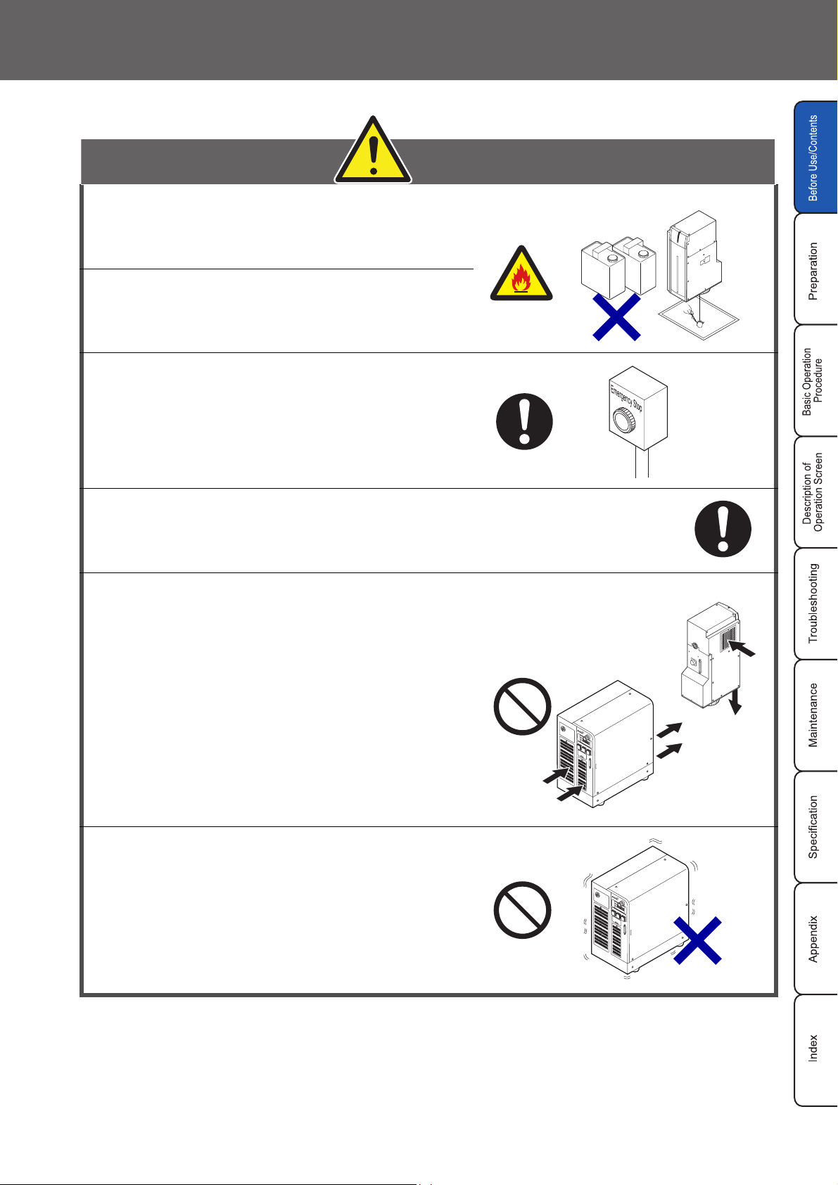
CAUTION
Use this product neither in inflammable
gas, a dusty place nor the place of fire
strict prohibition. It might cause a fire.
Never put the object which is easy to burn
on near. It might causes a fire.
Construct an interlock systems such as a
function to stop laser radiation for the
maintenance door of the protective
enclosure.
Before Use
Gasoline
Thinner
Use the product with the below environmental condition:
Ambient temperature
: 0 to +40 C (no condensation and icing)
Ambient humidity : 35 to 85%
°
(no condensation and icing)
The air cooling system is used for this product
as a laser cooling system. Please install not
to bar the flow of air cooling. Moreover,
please do not install a heat source in near,
either.
Since this product includes precision parts,
please avoid vibration and use in a place
with any shocks. Marking quality may
deteriorate or the optical system may be
affected. Moreover, please do not drop this
product.
Cautions in Handling 15
CAUTION
Never let water, oil, fingerprints, dust garbage,
etc. adhere to the lens part of the head. It might
result in deterioration of marking quality, and
failure. When cleaning, wipe with the dry soft
cloth etc. lightly.
Refer to “5-2 Contamination of fθ Lens” ( P.306).
Soft Cloth
Be sure to connect the head to the exclusive controller. It will
cause a failure if it connects with any equipment other than the
exclusive controller. Moreover, it may be exposed to dangerous
laser radiation.
When re-switching on the power supply, after turning OFF key
switch of the power supply BOX supply and 5 seconds or more
pass, turn ON key switch of the power supply BOX again.
When carrying the head part, carry
the head part as shown in the right
figure.
Clean air filter when it is dirty with dust etc. If the air filter is dirty,
the air-flow might become bad and might stop marking operation.
Exchange air filter periodically.
Refer to "5-1 Cleaning of Air Filter" ( P.308).
While marking is carried out, dust and/
or gas may be produced from the place
to be marked. Always ventilate and
remove them using a dust collector,
etc.
They may affect the marking quality badly.
Dust Collector
16 Cautions in Handling
Applicable Standards
This product is applied the following standards. When the system is exported as a single unit or a part
mounted on other machines or equipment, prior to exporting, make sure that the system may meet the
requirement of the standards in countries or regions where the system is to be exported.
LP-V10U, LP-V15U, LP-W052U: JIS (Japanese Industrial Standards)
This product is compliant to the "Safety of laser products" (JIS C 6802).
LP-V10U-A, LP-V15U-A, LP-W052U-A: FDA
T
he "Radiation Control for Health and Safety" gives the restriction to the manufacturer of the laser products to be marketed in the U.S.A., and obliges to adapt the laser product to the reference. The FDA (Food
and Drug Administration) constitutes the “PART 1040 PERFORMANCE STANDARDS FOR LIGHTEMITTING PRODUCTS” in accordance with the performance standards of the laser products, regulates
this performacen standards in FDA Standard (21 CFR 1040.10 and 1040.11), and is compliant with this
standard.
Other Cautions
1. Prior to wiring and/or cable connecting work, ensure that all the power has been turned off.
2. USB cable should not be connected in parallel with AC power or the power cable of monitor.
3. Use the accessory cables attached to the system for connecting cables without fail.
Before Use
4. Be sure that the supplied power does not exceed the rating. Prior to turning the power on, check any change
in voltage.
5. If a surge occurs in the power supplied, connect a surge absorber to a source of the surge to absorb it.
6. Make sure to ground a terminal of a frame ground (F.G.) of the system.
7. Install such that the controller housing and the head housing are at the same electric potential.Install such that
the controller housing and the head housing are at the same electric potential.
Laser Marker which can be controlled by Laser Marker NAVI is controller version 2.2X and after of LP-400/V/W
8.
series Laser Marker.
9. When using the optional console (LP-ADP40), take care the items below.
The console is formed with a resin case. If it is dropped, it may be cracked. Care must be taken not to
damage it.
The indicator section is composed of a touch panel. Do not use a sharp-pointed object to operate the
touch panel, which may break the touch panel. Operate it with a round-pointed object.
Cautions in Handling 17
Contents
Before Use
Preface ••••••••••••••••••••••••••••••••••••••••••••••••••••••••••••••••••••••••••••••••••••• 2
Caution in Handling Laser Beam•••••••••••••••••••••••••••••••••••••••••••••••••••••• 6
Safety Protection Measures•••••••••••••••••••••••••••••••••••••••••••••••••••••••••••• 8
Functions for Safety Measures ••••••••••••••••••••••••••••••••••••••••••••••••••••••• 10
Cautions in Handling••••••••••••••••••••••••••••••••••••••••••••••••••••••••••••••••••••14
Contents •••••••••••••••••••••••••••••••••••••••••••••••••••••••••••••••••••••••••••••••••• 18
Whole Manual Construction••••••••••••••••••••••••••••••••••••••••••••••••••••••••••• 23
Construction of Manual ••••••••••••••••••••••••••••••••••••••••••••••••••••••••••••••••24
"Let's Try" Contents••••••••••••••••••••••••••••••••••••••••••••••••••••••••••••••••••••• 26
1
Preparation
1-1 Package Check ••••••••••••••••••••••••••••••••••••••••••••••••••••••••••••••••••••• 30
1-2 Name of Each Part••••••••••••••••••••••••••••••••••••••••••••••••••••••••••••••••• 32
1-2-1 Head••••••••••••••••••••••••••••••••••••••••••••••••••••••••••••••••••••••••• 32
1-2-2 Controller •••••••••••••••••••••••••••••••••••••••••••••••••••••••••••••••••••33
1-3 Installation •••••••••••••••••••••••••••••••••••••••••••••••••••••••••••••••••••••••••••36
1-3-1 Installation Method•••••••••••••••••••••••••••••••••••••••••••••••••••••••• 36
1-3-2 Center of Marking ••••••••••••••••••••••••••••••••••••••••••••••••••••••••• 38
1-3-3 Useful Function for Installation •••••••••••••••••••••••••••••••••••••••••39
1-4 Connecting Laser Marker••••••••••••••••••••••••••••••••••••••••••••••••••••••••• 41
1-4-1 Connecting Head, Controller, Terminal Block ••••••••••••••••••••••• 42
1-4-2 When Using Console (Option)•••••••••••••••••••••••••••••••••••••••••• 42
1-4-3 When Using Monitor and Mouse•••••••••••••••••••••••••••••••••••••••42
1-5 Connection with External Devices •••••••••••••••••••••••••••••••••••••••••••••• 43
1-5-1 Operation Sample Using External Control •••••••••••••••••••••••••••43
1-5-2 Operation Procedures Using External Control ••••••••••••••••••••••44
1-5-3 Shift to Remote Mode ••••••••••••••••••••••••••••••••••••••••••••••••••••46
1-5-4 Shift to RUN Mode••••••••••••••••••••••••••••••••••••••••••••••••••••••••47
1-5-5 Terminal Block and I/O Connector••••••••••••••••••••••••••••••••••••• 48
1-5-6 RS-232C•••••••••••••••••••••••••••••••••••••••••••••••••••••••••••••••••••• 52
1-5-7 DIP Switch••••••••••••••••••••••••••••••••••••••••••••••••••••••••••••••••••54
2
18 Contents
Basic Operation Procedure
2-1 When Using Laser Marker for the First Time••••••••••••••••••••••••••••••••••56
2-1-1 Preparation of Laser Marker Operation••••••••••••••••••••••••••••••• 57
2-1-2 Startup of Laser Marker •••••••••••••••••••••••••••••••••••••••••••••••••• 58
2-1-3 Procedure from Laser Marker Setting to Marking•••••••••••••••••••59
2-1-4 Turn OFF Power of Laser Marker•••••••••••••••••••••••••••••••••••••• 69
2-2 Setting Procedure for Basic Function •••••••••••••••••••••••••••••••••••••••••• 70
2-2-1 Mark Counter •••••••••••••••••••••••••••••••••••••••••••••••••••••••••••••• 70
2-2-2 Mark Lot No. ••••••••••••••••••••••••••••••••••••••••••••••••••••••••••••••• 76
2-2-3 Mark Expiry Date ••••••••••••••••••••••••••••••••••••••••••••••••••••••••• 82
2-2-4 Mark Logo•••••••••••••••••••••••••••••••••••••••••••••••••••••••••••••••••• 88
2-2-5 Mark Date •••••••••••••••••••••••••••••••••••••••••••••••••••••••••••••••••• 92
2-2-6 Mark Flying Object ••••••••••••••••••••••••••••••••••••••••••••••••••••••• 96
2-2-7 Mark Step and Repeat Character ••••••••••••••••••••••••••••••••••••100
2-2-8 QR Code Setting•••••••••••••••••••••••••••••••••••••••••••••••••••••••••106
3
Description of Operation Screen
3-1 Description of Control Screen ••••••••••••••••••••••••••••••••••••••••••••••••••114
3-2 Operation Screen •••••••••••••••••••••••••••••••••••••••••••••••••••••••••••••••••116
3-2-1 Character Display•••••••••••••••••••••••••••••••••••••••••••••••••••••••• 116
3-2-2 Image Display ••••••••••••••••••••••••••••••••••••••••••••••••••••••••••••117
3-2-3 Password Function •••••••••••••••••••••••••••••••••••••••••••••••••••••• 118
3-3 Operator Adjustment Screen •••••••••••••••••••••••••••••••••••••••••••••••••••120
3-3-1 Outline •••••••••••••••••••••••••••••••••••••••••••••••••••••••••••••••••••••120
3-3-2 Setting Method •••••••••••••••••••••••••••••••••••••••••••••••••••••••••••121
3-4 Maintenance & Inspection•••••••••••••••••••••••••••••••••••••••••••••••••••••••126
3-4-1 I/O Check Monitor •••••••••••••••••••••••••••••••••••••••••••••••••••••••126
3-4-2 Error Log ••••••••••••••••••••••••••••••••••••••••••••••••••••••••••••••••••127
3-5 Selecting Marking Mode •••••••••••••••••••••••••••••••••••••••••••••••••••••••••128
3-5-1 Outline •••••••••••••••••••••••••••••••••••••••••••••••••••••••••••••••••••••128
3-5-2 Dual Pointer•••••••••••••••••••••••••••••••••••••••••••••••••••••••••••••••129
3-5-3 Guide Laser•••••••••••••••••••••••••••••••••••••••••••••••••••••••••••••••130
3-5-4 Test Marking ••••••••••••••••••••••••••••••••••••••••••••••••••••••••••••••132
3-5-5 RUN Mode ••••••••••••••••••••••••••••••••••••••••••••••••••••••••••••••••133
3-6 File •••••••••••••••••••••••••••••••••••••••••••••••••••••••••••••••••••••••••••••••••••134
3-6-1 Comment••••••••••••••••••••••••••••••••••••••••••••••••••••••••••••••••••134
3-6-2 Change File No.••••••••••••••••••••••••••••••••••••••••••••••••••••••••••135
3-6-3 Save••••••••••••••••••••••••••••••••••••••••••••••••••••••••••••••••••••••••136
3-6-4 Save to Different No.••••••••••••••••••••••••••••••••••••••••••••••••••••137
3-6-5 New Creation •••••••••••••••••••••••••••••••••••••••••••••••••••••••••••••138
3-7 Character Setting •••••••••••••••••••••••••••••••••••••••••••••••••••••••••••••••••140
3-7-1 Character Type•••••••••••••••••••••••••••••••••••••••••••••••••••••••••••140
3-7-2 Input and Edit Character •••••••••••••••••••••••••••••••••••••••••••••••143
3-7-3 Function Character ••••••••••••••••••••••••••••••••••••••••••••••••••••••149
3-8 Function Setting •••••••••••••••••••••••••••••••••••••••••••••••••••••••••••••••••••168
3-8-1 Expiry Date••••••••••••••••••••••••••••••••••••••••••••••••••••••••••••••••168
3-8-2 Counter ••••••••••••••••••••••••••••••••••••••••••••••••••••••••••••••••••••170
3-8-3 Lot ••••••••••••••••••••••••••••••••••••••••••••••••••••••••••••••••••••••••••172
3-8-4 Rank••••••••••••••••••••••••••••••••••••••••••••••••••••••••••••••••••••••••174
3-8-5 External Offset •••••••••••••••••••••••••••••••••••••••••••••••••••••••••••176
Contents 19
3-9 Marking Condition •••••••••••••••••••••••••••••••••••••••••••••••••••••••••••••••• 178
3-9-1 Overall Condition•••••••••••••••••••••••••••••••••••••••••••••••••••••••• 178
3-9-2 Character Condition •••••••••••••••••••••••••••••••••••••••••••••••••••• 185
3-9-3 Logo Condition •••••••••••••••••••••••••••••••••••••••••••••••••••••••••• 191
3-9-4 Bar Code Condition••••••••••••••••••••••••••••••••••••••••••••••••••••• 194
3-9-5 Processing Condition••••••••••••••••••••••••••••••••••••••••••••••••••• 232
3-10 Laser Setting••••••••••••••••••••••••••••••••••••••••••••••••••••••••••••••••••••• 232
3-10-1 Setting Parameters•••••••••••••••••••••••••••••••••••••••••••••••••••• 232
3-10-2 Line Width and Marking Pitch••••••••••••••••••••••••••••••••••••••• 235
3-10-3 Adjustment of Marking Quality •••••••••••••••••••••••••••••••••••••• 236
3-11 Trigger Setting••••••••••••••••••••••••••••••••••••••••••••••••••••••••••••••••••• 238
3-11-1 Marking to Static Work•••••••••••••••••••••••••••••••••••••••••••••••• 238
3-11-2 Marking to Flying Object ••••••••••••••••••••••••••••••••••••••••••••• 239
3-12 Common Setting •••••••••••••••••••••••••••••••••••••••••••••••••••••••••••••••• 258
3-12-1 Comment•••••••••••••••••••••••••••••••••••••••••••••••••••••••••••••••• 258
3-12-2 Common Character Setting ••••••••••••••••••••••••••••••••••••••••• 259
3-12-3 Common Expiry Date ••••••••••••••••••••••••••••••••••••••••••••••••• 260
3-12-4 Common Counter•••••••••••••••••••••••••••••••••••••••••••••••••••••• 261
3-12-5 Common Lot•••••••••••••••••••••••••••••••••••••••••••••••••••••••••••• 263
4
3-13 Image Display ••••••••••••••••••••••••••••••••••••••••••••••••••••••••••••••••••• 264
3-13-1 Image Display Screen •••••••••••••••••••••••••••••••••••••••••••••••• 264
3-13-2 Work Image Display••••••••••••••••••••••••••••••••••••••••••••••••••• 265
3-14 USB Media ••••••••••••••••••••••••••••••••••••••••••••••••••••••••••••••••••••••• 266
3-14-1 Registration File ••••••••••••••••••••••••••••••••••••••••••••••••••••••• 258
3-14-2 Common File ••••••••••••••••••••••••••••••••••••••••••••••••••••••••••• 270
3-14-3 Logo File •••••••••••••••••••••••••••••••••••••••••••••••••••••••••••••••• 264
3-14-4 Font File ••••••••••••••••••••••••••••••••••••••••••••••••••••••••••••••••• 268
3-14-5 Others ••••••••••••••••••••••••••••••••••••••••••••••••••••••••••••••••••• 282
3-15 Environment Setting•••••••••••••••••••••••••••••••••••••••••••••••••••••••••••• 286
3-15-1 Environment 1•••••••••••••••••••••••••••••••••••••••••••••••••••••••••• 286
3-15-2 Environment 2•••••••••••••••••••••••••••••••••••••••••••••••••••••••••• 291
3-15-3 Communication I/O•••••••••••••••••••••••••••••••••••••••••••••••••••• 294
3-15-4 Output Simulation ••••••••••••••••••••••••••••••••••••••••••••••••••••• 296
3-15-5 Power Check ••••••••••••••••••••••••••••••••••••••••••••••••••••••••••• 289
3-15-6 Adjustment of Touch Panel/Switching Language, etc. ••••••••• 292
Troubleshooting
20 Contents
4-1 Troubleshooting••••••••••••••••••••••••••••••••••••••••••••••••••••••••••••••••••• 296
4-2 Error Indication•••••••••••••••••••••••••••••••••••••••••••••••••••••••••••••••••••• 298
4-2-1 Alarm •••••••••••••••••••••••••••••••••••••••••••••••••••••••••••••••••••••• 298
4-2-2 Warning ••••••••••••••••••••••••••••••••••••••••••••••••••••••••••••••••••• 300
5
Maintenance
5-1 Cleaning of Air Filter••••••••••••••••••••••••••••••••••••••••••••••••••••••••••••••304
5-1-1 Cleaning of Air Filter ••••••••••••••••••••••••••••••••••••••••••••••••••••304
5-1-2 Replacement of Air Filter•••••••••••••••••••••••••••••••••••••••••••••••305
5-2 Contamination of fθLens •••••••••••••••••••••••••••••••••••••••••••••••••••••••306
5-3 Replacement of Fuse ••••••••••••••••••••••••••••••••••••••••••••••••••••••••••••307
5-4 Maintenance Parts and Procurement •••••••••••••••••••••••••••••••••••••••••308
6
Specification
6-1 Specification •••••••••••••••••••••••••••••••••••••••••••••••••••••••••••••••••••••••310
6-2 Outer Dimensional Drawing•••••••••••••••••••••••••••••••••••••••••••••••••••••312
6-2-1 Head •••••••••••••••••••••••••••••••••••••••••••••••••••••••••••••••••••••••312
6-2-2 Controller••••••••••••••••••••••••••••••••••••••••••••••••••••••••••••••••••314
6-2-3 Console (Option)•••••••••••••••••••••••••••••••••••••••••••••••••••••••••315
Appendix
Radiation Information•••••••••••••••••••••••••••••••••••••••••••••••••••••••••••••••••318
Safety Standard of Laser Product •••••••••••••••••••••••••••••••••••••••••••••••••320
Safety Measures Operation •••••••••••••••••••••••••••••••••••••••••••••••••••••••••322
Description of Code Symbols•••••••••••••••••••••••••••••••••••••••••••••••••••••••324
Readable DXF File••••••••••••••••••••••••••••••••••••••••••••••••••••••••••••••••••••340
Character Code Table••••••••••••••••••••••••••••••••••••••••••••••••••••••••••••••••342
Index
Index•••••••••••••••••••••••••••••••••••••••••••••••••••••••••••••••••••••••••••••••••••••364
Contents 21

MEMO
22 Contents
Whole Manual Construction
This laser marker is prepared for the following manuals. Read the corresponding manual for the target, and operate
this laser marker fully. Also, store these manuals after reading them.
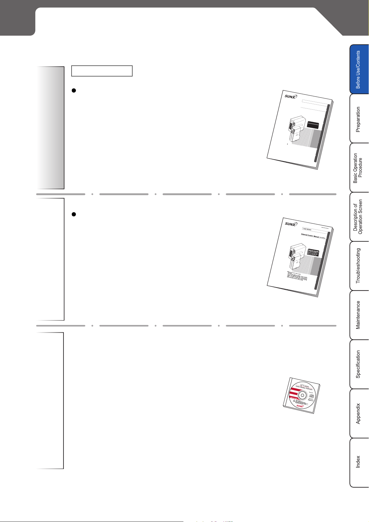
This Manual
This manual describes the items required for the introduction,
installation, and operation of the laser marker.
The following contents, cautions, preparation for introducing,
installing, and wiring the laser marker after unpacking, basic
active operation, screen operation for setting marking contents,
measurement and maintenance for error and maintenance
inspection, and specifications are described in this manual.
Laser Maker
Laser Maker
Mainly the users that operate this laser marker for actual marking procedure shall be required for reading this manual.
Operation Manual
This manual describes the items required for the introduction
and installation of the laser marker, and for the external control of the laser marker.
•Control from Terminal Block, I/O Connector:
Describes the signal layout of the terminal block and I/O connector, I/O rating, timing chart, example of control, etc.
•Control from RS-232C connector:
Describes the signal layout of the connector, communication
data format, communication command, example of control,
etc.
ME-LPV10 No. 1219-02
Laser Marker
LP-V/W
SERIES
Operation Manual
3rd Edition
"Let's Try" Contents
The "Let's Try" contents is
prepraed in P.22 of th
Refer to corresponding page
is manual.
that the user wants to try
.
Please use the laser marker properly.
Laser Beam
The laser beam applied for this laser marker is equal to
Class 4 Laser dealt in JIS Standard. Take care of not
looking or touching direct laser beam and its reflected
beam. Be sure to take safety measures that is
appropriated t
o the cont
ents of
wa
rning labels.
LP-V/W
SERIES
Mainly the provider and system designer shall be required for reading
this manual.
External Control Manual
For marking logo data and image data using the laser marker, it
needs to convert the data. This manual describes how to install the
logo data conversion software up to convert/output data.
Besides, the operation for the font maker that enables to create
character to be marked freely.
Mainly the provider and system designer shall be required for reading
this manual.
Operation Manual
Logo Data Convert/Font Maker
* The PDF data of the Logo Data Conversion/Font Maker Software Operation Manual are stored in attached
CD-ROM of this manual.
The published manual is not prepared for the Logo Data Conversion/Font Maker Software Operation Manual.
*
Whole Manual Construction 23
Construction of Manual
Maintenance
The important items for safety laser
marker operation are described in
Before Use
this section.
Be sure to read this section before
using the laser marker.
)P. 2
Chapter
1
Chapter
2
Chapter
3
Chapter
4
This chapter describes the items
Preparation
Basic Operation
Procedure
Description of Operation Screen
Troubleshooting
required for using the laser marker.
Be sure to read this chapter at
preparation.
This chapter describes the basic
operation targetting for the first user
briefly. Since the control sample is
also involved, refer to them together.
Read this chapter for operating the
laser marker such as the setting
character to be marked and the
function for marking.
This chapter describes the error
messages and measures. Read this
chapter when error message is
appeared or marking is not performed
properly.
)P. 2 9
)P. 5 5
)P. 11 3
)P. 2 95
Chapter
5
Chapter
6
Appendix
Maintenance
Specification
Index
This chapter describes the maintenance,
replacement of filter and cleaning of lens,
etc.
Please read this chapter when performing
maintenance.
This chapter describes the specification
and outer dimension of laser marker.
This appendix describes the character
code table.
With this table, the code of character
and symbols to be marked can be
checked.
With this index, the corresponding
page describing details for desired
contents using the terms.
)P. 3 03
)P. 3 09
)P. 3 17
)P. 3 63
24 Construction of Manual
MEMO
Before Use
Construction of Manual 25
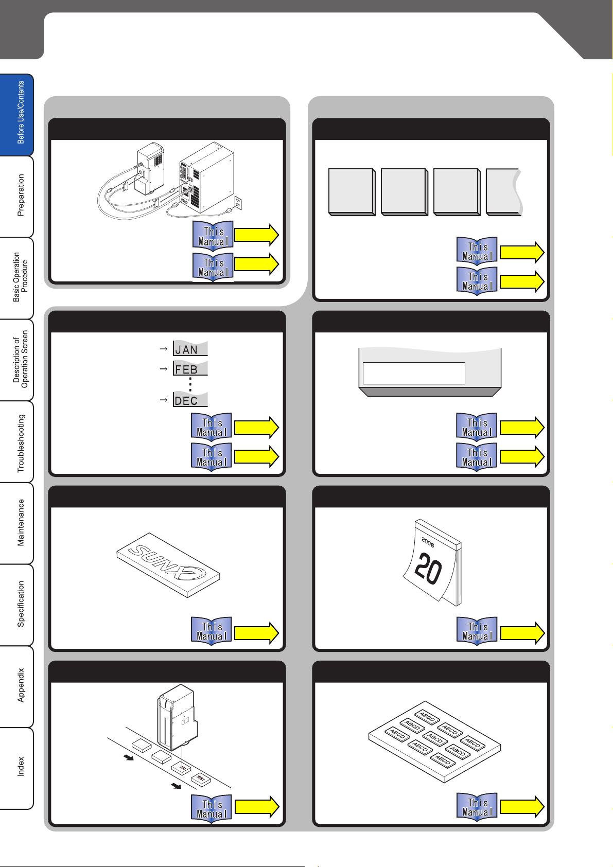
"Let's Try" Contents
The user can refer to the corresponding pages in which the contents of what user "tries to do" are described
using this "Let's Try" Contents.
Setup Laser Marker
Install and Connect
"Installation"
"Connecting Laser Marker"
Mark Lot Symbol Mark Expiry Date
January
February
December
P. 3 6
P. 4 1
Marking
Mark Counter
0001000200030004
"Mark Counter"
"Counter"
Expiry DateExpiry Date
2006
.11.20.
P. 1 7 0
…
P. 7 0
"Mark Lot No."
"Lot"
P. 7 6
P.172
"Mark Expiry Date"
"Expiry Date"
Mark Logo Mark Date
"Mark Logo"
P. 8 8
"Mark Date"
Mark Flying Object Mark Step and Repeat
P. 8 2
P. 1 6 8
P. 9 2
"Mark Flying Object"
26 "Let's Try" Contents
P. 9 6
"Mark Step and Repeat"
P.100
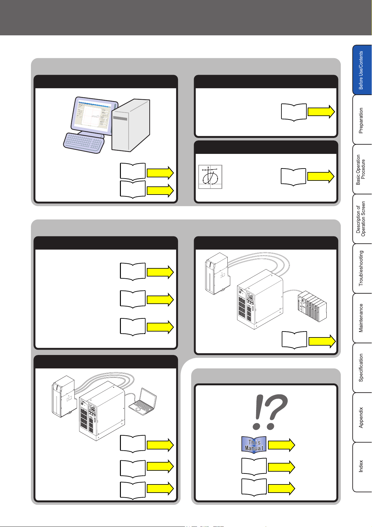
Make and Edit LogoData Convert and Font
Before Use
Description of Software
Logo Data Convert Software
Font Maker
Logo Data Conversion
Font Maker Software
Operation Manual
Logo Data Conversion
Font Maker Software
Operation Manual
/
P. 1 0
/
P. 1 0
Control Laser Marker from External
Check Item before Controlling from External
Convert Logo Data
"Convert Logo Data"
Logo Data Conversion
Font Maker Software
Operation Manual
/
P. 2 0
Make Font
"Make Font"
Logo Data Conversion
Font Maker Software
Operation Manual
/
P. 4 0
Control by Terminal Block and I/O
"Check DIP Switch"
"Check Basic Operation Procedure"
"Set Remote Mode"
Control by RS-232C
"Control by RS-232C"
External
Control
Manual
External
Control
Manual
External
Control
Manual
Personal
Computer
External
Control
Manual
P. 4 6
P. 4 3
P. 4 4
P. 7 9
"Control by Terminal Block·I/O"
When in Trouble...
P295
External
Control
Manual
PLC
P. 4 7
"Look Through Communication
Command"
"Read Description of Each
Command"
External
Control
Manual
External
Control
Manual
P. 9 7
P. 9 8
External
Control
Manual
Logo Data Conversion
Font Maker Software
Operation Manual
P. 1 4 7
/
P. 6 7
"Let's Try" Contents 27
MEMO
28 "Let's Try" Contents
1
Preparation
1-1 Package Check••••••••••••••••••••••••••••••••••••••••••••••••••••••••••••••••••••• 30
1-2 Name of Each Part •••••••••••••••••••••••••••••••••••••••••••••••••••••••••••••••• 32
1-3 Installation ••••••••••••••••••••••••••••••••••••••••••••••••••••••••••••••••••••••••••• 35
1-4 Connecting Laser Marker •••••••••••••••••••••••••••••••••••••••••••••••••••••••• 42
1-5 Connection with External Devices •••••••••••••••••••••••••••••••••••••••••••••• 44
29
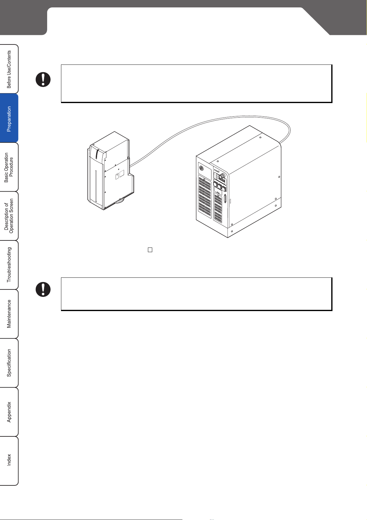
1-1 Package Check
Before using this product, be sure to check the packed objects shown below.
This product is delivered in sets with 1 package.
Be sure to store the packing material.
Since this product is delicate one, apply the packing material that is used for this product for pre-
CHECK
venting from the failure caused by transferring.
CHECK
Laser Marker
Both the head and controller are connected with fiber transmission cable. This cable cannot be
detached from the device.
Main Body
1 unit
30 1-1 Package Check
Loading...