


 Loading...
/' .2< 12 0Q 8
3D Control FAYb Laser Marker
LP-Z 


1st 


 12
12


Preface
Tank you for purchasing Laser Marker .
For full use of this laser marker safely and properly, please read this manual carefully.
This product has been strictly checked and tested prior to its delivery, however, please make sure that this product operates properly before using it.
In case that the product becomes damaged or does not operate as specified in this manual, contact the shop you bought it or our sales agency.

 Symbol Indications
This manual uses a variety of symbols to explain safety precautions, instructions, and references for operating personnel.
Before reading this manual, fully understand the contents of these indications.
DANGER
WARNING
"DANGER" denotes hazards that could result in serious personnel injury or death when handling error occurs, and emergency precautions (urgency level) when any dangerous situation causes.
"WARNING" denotes hazards that could result in serious personnel injury or death when handling error occurs.
"CAUTION" denotes that any damages on personnels or objects could result in when handling error occurs.
CAUTION
This symbol denotes the possibility of fire.
This symbol denotes a general prohibition notice.
This symbol denotes the prohibition of disassembling the product.
This symbol denotes the prohibition of touching the specified place.
This symbol denotes a general action which operators must take.
"CHECK" denotes any instructions or precautions for using this product.
CHECK
"REFERENCE" denotes any hints for operation, detail explanations, or references.
REFERENCE

 Note
Note
1.This manual is subject to LP-Z series. Be careful that the illustrations shown in the manual might be different.
2.Contents of this manual will be changed without notice. This manual and software must not be partially or totally copied or revised.
3.If there are any questions, mistakes, or comments in this manual, please notify us.
4.Please remind that we do not have responsibility of any results of operations in regardless of the above 3 clauses.
2 Preface
Before Use
 Features
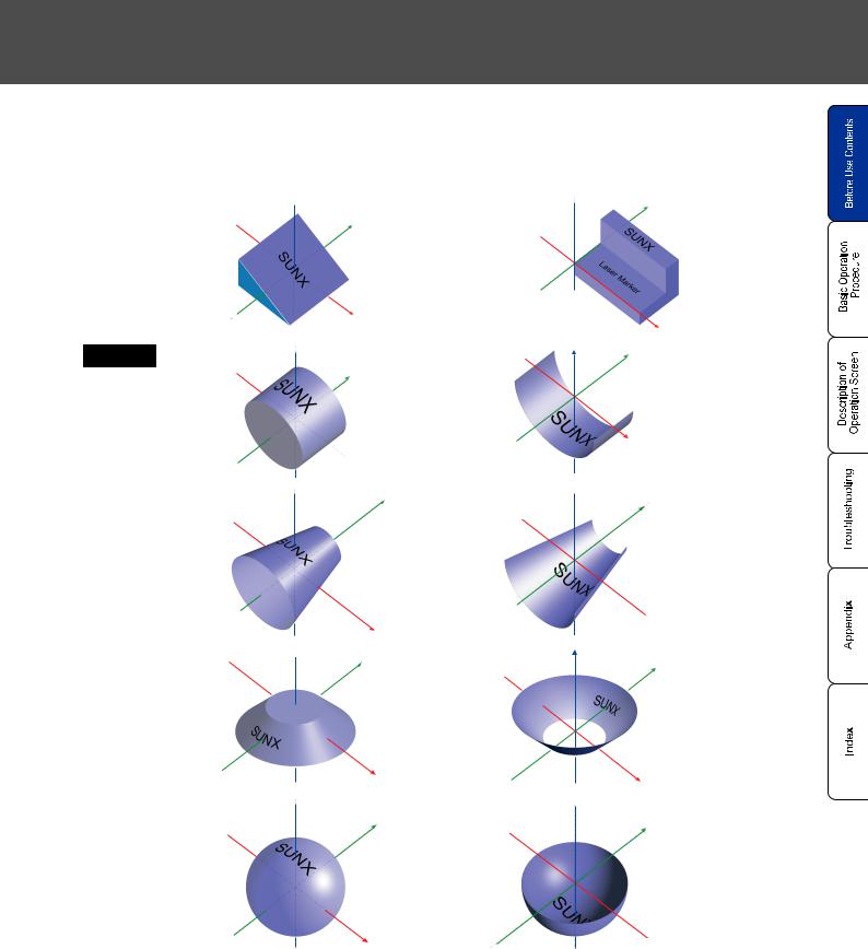
This LP-Z series is FAYb Laser Maker with the Z axis stroke feature. A new-developed FAYb laser and Z axis module can realize “wide-area marking“, and “3D marking“, even though its small head.
3D marking can be avaiable for the following 3D figures. (For details, refer to "Layer Condition"( P.175).)
Plane |
Mark on |
|
plane (slope) |
|
 Z
Z
Y
Mark on plane (uneven)
 Z Y
Z Y
X
X
Cylinder Mark on convex
face
 Z
Z
Y
 X
X
Mark on concave face
Z |
Y |
X
Horizontal |
Mark on |
Cone |
convex |
|
face |
|
|
Mark on |
Vertical |
|
Cone |
convex |
|
face |
|
 Z
Z  Y
Y
 X
X
 Z
Z  Y
Y
Mark on concave face
Mark on concave face
 Z
Z
 Y
Y
 X
X
Z
Y
X |
X |
|
|
Mark on |
Sphere |
|
|
convex |
|
|
|
face |
 Z
Z
Y
Mark on concave face
 Z
Z
Y
X 
 X
X
Preface 3
 Coordinate System (World Coordinate / Local Coordinate)
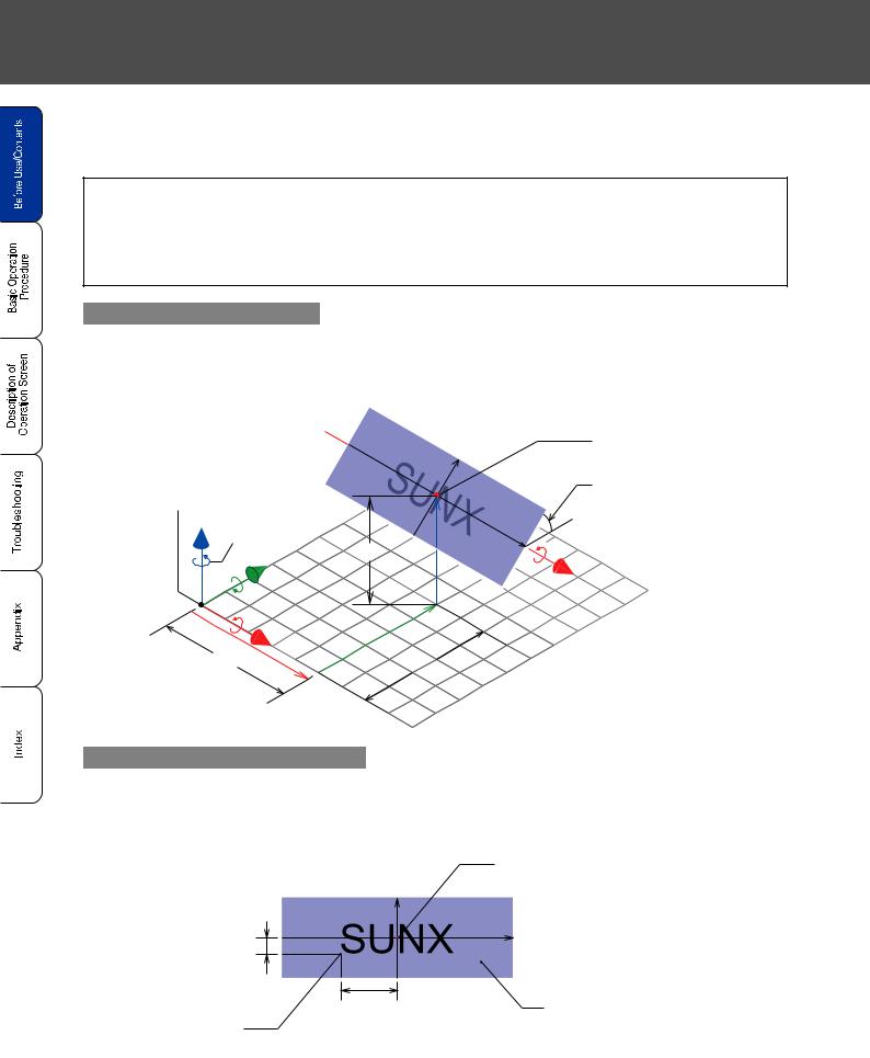
When marking to 3D figure (slope, cylindar, cone, sphere), the compatible coordinate is determined depending on the 3D figure (layer) and marking content (character, barcode, logo. etc.).
• 3D figure (layer)
The compatible coordinate is world coordinate (coordinate system with the center of area set to as original point). Specify the center position of the 3D figure as the original point for marking.
• Marking content (character, barcode, logo, etc.)
The compatible coordinate is local coordinate (coordinate system with the center of the 3D figure set to as original point). Specifiy the starting position of the marking content as the original point for marking.
Coordinate setting for 3D figure
When setting each center position of the 3D figure (layer: slope), center position X: 10mm, center position Y: 10mm, and center position Z: 8mm, these positions are set on the world coordinate shown as follows.
Original Point of |
Y |
|
|
||
World Coordinate |
|
|
Z’ Rotation |
|
|
Direction |
OO |
|
Y’ |
||
Z |
||
|
X’ |
Y |
OO |
X |
OO |
|
X
Center of 3D Figure
(Original Point of
Local Coordinate)
Rotation Angle X: +45[
Coordinate setting for marking content
When setting the starting position of the marking content, X position: -4mm, Y position: -1mm, each setting condition is set on the local coordinate as follows.
|
Original Point of |
Y |
Local Coordinate |
|
X
OO
OO |
3D Figure (Slope) |
Starting
Position
4 Preface

Before Use
 3D Marking Method
There are two methods for marking 3D figure, “Label Sticking Marking Method” and “Vertical Projection Marking Method”. The marking methodis determinied depending on the type of the 3D figure.
•Label sticking marking method
Type of 3D figure: plane, cylinder (marking on convex /concave face), horizontal cone (marking on convex /concave face)
•Vertical projection marking method
Type of 3D figure: vertical cone (marking on convex /concave face), sphere (marking on convex /concave face)
Label sticking marking method
•With this method, the laser marker performs the marking on the 3D figure like sticking label on the 3D figure.
Target type of 3D figure: plane, cylinder (marking on convex/concave face), sphere (marking on convex /concave face)
ABCDEFGHC |
|||
A |
B |
G |
H |
|
|
||
Character
Starting
Position
A
|
DE |
|
|
C |
F |
||
B |
|
|
G |
H
[Marking image on convex face of cylinder] |
[Sticking-like image] |
•When marking on cylinder and cone, set the starting position of marking content X and Y by measuring the length on curved face.
•When setting status of the marking content exceeds the figure area (see figure below) and starting marking, the marking error (E671/E672) is occurred and the laser marker cannot perform marking. Therefore, check the marking content using “3D View Screen” ("2-13-3 3D
View Screen"( P.298))‚ and perform guide indication of the marking character before marking. When the marking content is displayed within the figure area, start the marking.
CHECK
[Plane] |
[Cylinder (marking on |
|
convex face)] |
Marking Setting Character “ABCDEFGHIJKLMNOPQR”
Preface 5
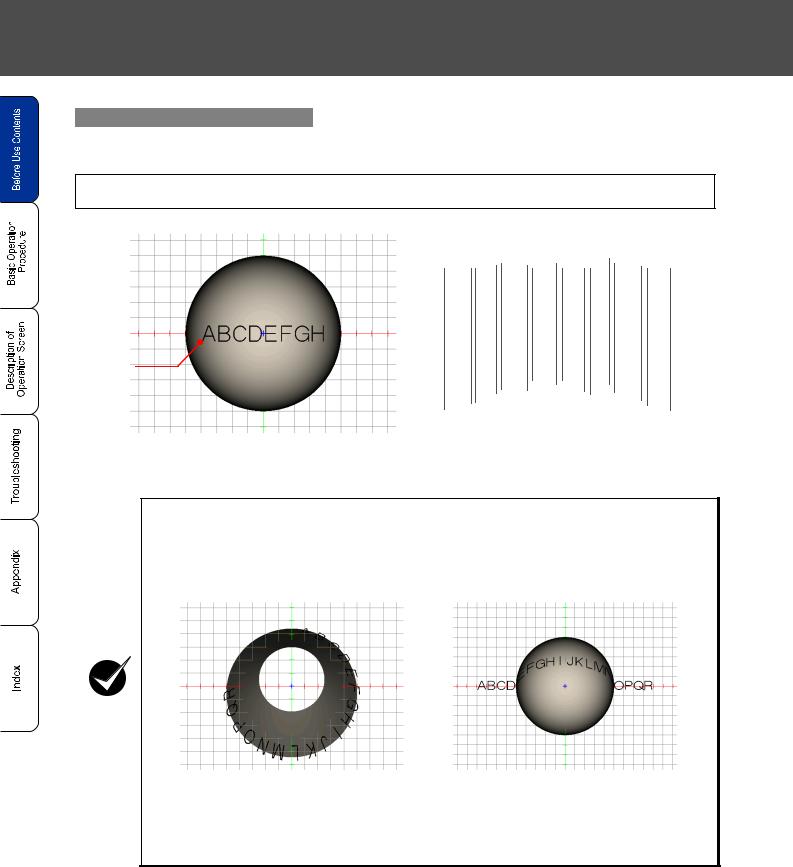
Vertical projection marking method
•With this method, the laser marker performs the markng on the 3D figure like vertical-projecting marking content onto the 3D figure.
Target type of 3D figure: vertical cone (marking on convex /concave face), sphere (marking on convex / concave face)
Character
Starting
Position
[Marking image on convex face of sphere viewing from top]
ABCDEFGH
|
C |
DE |
|
|
|
F |
|
||
A |
B |
|
G |
H |
|
|
|
||
[Sticking-like image]
•When setting status of the marking content exceeds the figure area (see figure below) and starting marking, the marking error (E671/E672) is occurred and the laser marker cannot perform marking. Therefore, check the marking content using “3D View Screen” ("2-13-3 3D
View Screen"( P.298))‚ and perform guide indication of the marking character before marking. When the marking content is displayed within the figure area, start the marking.
CHECK
[Marking image cone with its |
Marking image on convex face |
heightwise set parallel to Z axis] |
of sphere] |
Marking Setting Character “ABCDEFGHIJKLMNOPQR”
6 Preface

Contents
Before Use
Preface•••••••••••••••••••••••••••••••••••••••••••••••••••••••••••••••••••••••••••••••••••••••2
Contents •••••••••••••••••••••••••••••••••••••••••••••••••••••••••••••••••••••••••••••••••••••7
Whole Manual Construction ••••••••••••••••••••••••••••••••••••••••••••••••••••••••••• 10 Construction of Manual ••••••••••••••••••••••••••••••••••••••••••••••••••••••••••••••••• 11
"Let's Try" Contents ••••••••••••••••••••••••••••••••••••••••••••••••••••••••••••••••••••• 12
 1 Ch Basic Operation Procedure
1-1 When Using Laser Marker for the First Time ••••••••••••••••••••••••••••••••• 16
1-1-1 Preparation of Laser Marker Operation••••••••••••••••••••••••••••••••••••••••••••••••• 17 1-1-2 Startup of Laser Marker•••••••••••••••••••••••••••••••••••••••••••••••••••••••••••••••••••• 18 1-1-3 Procedure from Laser Marker Setting to Marking •••••••••••••••••••••••••••••••••••• 19 1-1-4 Turn OFF Power of Laser Marker ••••••••••••••••••••••••••••••••••••••••••••••••••••••• 29
1-2 Setting Procedure for Basic Function •••••••••••••••••••••••••••••••••••••••••• 30
1-2-1 Mark Counter •••••••••••••••••••••••••••••••••••••••••••••••••••••••••••••••••••••••••••••••• 30 1-2-2 Mark Lot No. ••••••••••••••••••••••••••••••••••••••••••••••••••••••••••••••••••••••••••••••••• 36 1-2-3 Mark Expiry Date•••••••••••••••••••••••••••••••••••••••••••••••••••••••••••••••••••••••••••• 42 1-2-4 Mark Logo •••••••••••••••••••••••••••••••••••••••••••••••••••••••••••••••••••••••••••••••••••• 48 1-2-5 Mark Date •••••••••••••••••••••••••••••••••••••••••••••••••••••••••••••••••••••••••••••••••••• 54 1-2-6 Mark Flying Object•••••••••••••••••••••••••••••••••••••••••••••••••••••••••••••••••••••••••• 58 1-2-7 Mark Step & Repeat•••••••••••••••••••••••••••••••••••••••••••••••••••••••••••••••••••••••• 62 1-2-8 QR Code Setting •••••••••••••••••••••••••••••••••••••••••••••••••••••••••••••••••••••••••••• 68
1-3 Basic Setting Procedure for Marking 3D Figure ••••••••••••••••••••••••••••• 76
1-3-1 Mark on Slope ••••••••••••••••••••••••••••••••••••••••••••••••••••••••••••••••••••••••••••••• 77 1-3-2 Mark on Uneven Figure•••••••••••••••••••••••••••••••••••••••••••••••••••••••••••••••••••• 80 1-3-3 Mark on Cylinder •••••••••••••••••••••••••••••••••••••••••••••••••••••••••••••••••••••••••••• 85 1-3-4 Mark on Cylinder (2)•••••••••••••••••••••••••••••••••••••••••••••••••••••••••••••••••••••••• 88 1-3-5 Mark on Cone•••••••••••••••••••••••••••••••••••••••••••••••••••••••••••••••••••••••••••••••• 92 1-3-6 Mark on Cone (2) ••••••••••••••••••••••••••••••••••••••••••••••••••••••••••••••••••••••••••• 95 1-3-7 Mark on Sphere ••••••••••••••••••••••••••••••••••••••••••••••••••••••••••••••••••••••••••••• 98
 2 Ch Description of Operation Screen
2-1 Description of Control Screen ••••••••••••••••••••••••••••••••••••••••••••••••••102
2-2 Operation Screen •••••••••••••••••••••••••••••••••••••••••••••••••••••••••••••••••104
2-2-1 Character Display••••••••••••••••••••••••••••••••••••••••••••••••••••••••••••••••••••••••••104
2-2-2 Image Display Screen•••••••••••••••••••••••••••••••••••••••••••••••••••••••••••••••••••••105
2-2-3 Password Function ••••••••••••••••••••••••••••••••••••••••••••••••••••••••••••••••••••••••106
2-3 Operator Adjustment Screen •••••••••••••••••••••••••••••••••••••••••••••••••••108
2-3-1 Outline •••••••••••••••••••••••••••••••••••••••••••••••••••••••••••••••••••••••••••••••••••••••108
2-3-2 Setting Method •••••••••••••••••••••••••••••••••••••••••••••••••••••••••••••••••••••••••••••109
2-4 Maintenance & Inspection•••••••••••••••••••••••••••••••••••••••••••••••••••••••114
2-4-1 I/O Check Monitor •••••••••••••••••••••••••••••••••••••••••••••••••••••••••••••••••••••••••114
2-4-2 Error Log•••••••••••••••••••••••••••••••••••••••••••••••••••••••••••••••••••••••••••••••••••••115
Contents 7

2-5 Selecting Marking Mode •••••••••••••••••••••••••••••••••••••••••••••••••••••••• 116
2-5-1 Outline••••••••••••••••••••••••••••••••••••••••••••••••••••••••••••••••••••••••••••••••••••••••116
2-5-2 Dual Pointer•••••••••••••••••••••••••••••••••••••••••••••••••••••••••••••••••••••••••••••••••117
2-5-3 Guide Laser •••••••••••••••••••••••••••••••••••••••••••••••••••••••••••••••••••••••••••••••••118
2-5-4 Test Marking ••••••••••••••••••••••••••••••••••••••••••••••••••••••••••••••••••••••••••••••••121
2-5-5 RUN Mode ••••••••••••••••••••••••••••••••••••••••••••••••••••••••••••••••••••••••••••••••••122
2-6 FILE ••••••••••••••••••••••••••••••••••••••••••••••••••••••••••••••••••••••••••••••••• 124
2-6-1 Comment ••••••••••••••••••••••••••••••••••••••••••••••••••••••••••••••••••••••••••••••••••••124
2-6-2 Change File No. ••••••••••••••••••••••••••••••••••••••••••••••••••••••••••••••••••••••••••••125
2-6-3 Save ••••••••••••••••••••••••••••••••••••••••••••••••••••••••••••••••••••••••••••••••••••••••••126
2-6-4 Save to Different No. ••••••••••••••••••••••••••••••••••••••••••••••••••••••••••••••••••••••127
2-6-5 New Creation •••••••••••••••••••••••••••••••••••••••••••••••••••••••••••••••••••••••••••••••128
2-7 Character Setting••••••••••••••••••••••••••••••••••••••••••••••••••••••••••••••••• 130
2-7-1 Character Type •••••••••••••••••••••••••••••••••••••••••••••••••••••••••••••••••••••••••••••130
2-7-2 Input and Edit Character••••••••••••••••••••••••••••••••••••••••••••••••••••••••••••••••••133
2-7-3 Function Character ••••••••••••••••••••••••••••••••••••••••••••••••••••••••••••••••••••••••139
2-8 Function Setting •••••••••••••••••••••••••••••••••••••••••••••••••••••••••••••••••• 158
2-8-1 Expiry Date••••••••••••••••••••••••••••••••••••••••••••••••••••••••••••••••••••••••••••••••••158
2-8-2 Counter ••••••••••••••••••••••••••••••••••••••••••••••••••••••••••••••••••••••••••••••••••••••160
2-8-3 Lot•••••••••••••••••••••••••••••••••••••••••••••••••••••••••••••••••••••••••••••••••••••••••••••162
2-8-4 Rank ••••••••••••••••••••••••••••••••••••••••••••••••••••••••••••••••••••••••••••••••••••••••••164
2-8-5 External Offset••••••••••••••••••••••••••••••••••••••••••••••••••••••••••••••••••••••••••••••166
2-9 Marking Condition •••••••••••••••••••••••••••••••••••••••••••••••••••••••••••••••• 170
2-9-1 GENERAL •••••••••••••••••••••••••••••••••••••••••••••••••••••••••••••••••••••••••••••••••••170
2-9-2 Character Conditions••••••••••••••••••••••••••••••••••••••••••••••••••••••••••••••••••••••200
2-9-3 Logo Conditions ••••••••••••••••••••••••••••••••••••••••••••••••••••••••••••••••••••••••••••210
2-9-4 Bar Code Condition••••••••••••••••••••••••••••••••••••••••••••••••••••••••••••••••••••••••214
2-9-5 Processing Condition••••••••••••••••••••••••••••••••••••••••••••••••••••••••••••••••••••••260
2-9-6 Fixed Point Radiation Condition•••••••••••••••••••••••••••••••••••••••••••••••••••••••••268
2-10 Laser Setting••••••••••••••••••••••••••••••••••••••••••••••••••••••••••••••••••••• 270
2-10-1 Setting Parameters•••••••••••••••••••••••••••••••••••••••••••••••••••••••••••••••••••••••270
2-10-2 Line Width •••••••••••••••••••••••••••••••••••••••••••••••••••••••••••••••••••••••••••••••••274
2-10-3 Marking Quality Adjustment ••••••••••••••••••••••••••••••••••••••••••••••••••••••••••••275
2-11 Trigger Setting••••••••••••••••••••••••••••••••••••••••••••••••••••••••••••••••••• 278
2-11-1 Marking to Still Work•••••••••••••••••••••••••••••••••••••••••••••••••••••••••••••••••••••278 2-11-2 Marking to Flying Object ••••••••••••••••••••••••••••••••••••••••••••••••••••••••••••••••279
2-12 Common Setting •••••••••••••••••••••••••••••••••••••••••••••••••••••••••••••••• 290
2-12-1 Comment•••••••••••••••••••••••••••••••••••••••••••••••••••••••••••••••••••••••••••••••••••290
2-12-2 Common Expiry Date••••••••••••••••••••••••••••••••••••••••••••••••••••••••••••••••••••291
2-12-3 Common Counter ••••••••••••••••••••••••••••••••••••••••••••••••••••••••••••••••••••••••292
2-12-4 Common Lot•••••••••••••••••••••••••••••••••••••••••••••••••••••••••••••••••••••••••••••••294
2-13 Image Display Screen ••••••••••••••••••••••••••••••••••••••••••••••••••••••••• 296
2-13-1 Image Display Screen •••••••••••••••••••••••••••••••••••••••••••••••••••••••••••••••••••296
2-13-2 Work image display ••••••••••••••••••••••••••••••••••••••••••••••••••••••••••••••••••••••297
2-13-3 3D View Screen•••••••••••••••••••••••••••••••••••••••••••••••••••••••••••••••••••••••••••298
8 Contents

Contents
2-14 USB Media••••••••••••••••••••••••••••••••••••••••••••••••••••••••••••••••••••••••300
2-14-1 Registration File ••••••••••••••••••••••••••••••••••••••••••••••••••••••••••••••••••••••••••300
2-14-2 Common File ••••••••••••••••••••••••••••••••••••••••••••••••••••••••••••••••••••••••••••••304
2-14-3 Logo File •••••••••••••••••••••••••••••••••••••••••••••••••••••••••••••••••••••••••••••••••••307
2-14-4 Font File••••••••••••••••••••••••••••••••••••••••••••••••••••••••••••••••••••••••••••••••••••310
2-14-5 Others ••••••••••••••••••••••••••••••••••••••••••••••••••••••••••••••••••••••••••••••••••••••316
2-15 Environment Setting ••••••••••••••••••••••••••••••••••••••••••••••••••••••••••••320
2-15-1 Environment 1•••••••••••••••••••••••••••••••••••••••••••••••••••••••••••••••••••••••••••••320
2-15-2 Environment 2•••••••••••••••••••••••••••••••••••••••••••••••••••••••••••••••••••••••••••••325
2-15-3 Environment 3•••••••••••••••••••••••••••••••••••••••••••••••••••••••••••••••••••••••••••••328
2-15-4 Output Simulation ••••••••••••••••••••••••••••••••••••••••••••••••••••••••••••••••••••••••330
2-15-5 Power check•••••••••••••••••••••••••••••••••••••••••••••••••••••••••••••••••••••••••••••••331 2-15-6 Adjustment of Touch Panel/Switching Language ••••••••••••••••••••••••••••••••••334
 3 Ch Troubleshooting
3-1 Troubleshooting •••••••••••••••••••••••••••••••••••••••••••••••••••••••••••••••••••338
3-2 Error Indication ••••••••••••••••••••••••••••••••••••••••••••••••••••••••••••••••••••340
3-2-1 Alarm •••••••••••••••••••••••••••••••••••••••••••••••••••••••••••••••••••••••••••••••••••••••••340
3-2-2 Warning ••••••••••••••••••••••••••••••••••••••••••••••••••••••••••••••••••••••••••••••••••••••342
Appendix
Description of Code Symbols ••••••••••••••••••••••••••••••••••••••••••••••••••••••••348
Readable DXF File •••••••••••••••••••••••••••••••••••••••••••••••••••••••••••••••••••••371
Character Code Table •••••••••••••••••••••••••••••••••••••••••••••••••••••••••••••••••372
Input Setting Value by Series ••••••••••••••••••••••••••••••••••••••••••••••••••••••••392
Index
Index ••••••••••••••••••••••••••••••••••••••••••••••••••••••••••••••••••••••••••••••••••••••396
Contents 9

Whole Manual Construction
This laser marker is prepared for the following manuals. Read the corresponding manual for the target, and operate this laser marker fully. Also, store these manuals after reading them.
Safety Guide
This manual describes the safety items required for using the laser marker.
& LP-Z
(#;D SERIES
MJ-LP |
No. 0010-25V |
|


MJ-LP |
No. 0010-26V |
|
Setup Guide
This manual describes the items required for the introduction and installation of the laser marker.
& |
(#;D |
LP-Z |
|
|
SERIES |


Operation Manual
Laser Marker
This Manual
This manual describes the items required for the operation of the laser marker.
The following contents, cautions, basic active operation, screen operation for setting marking contents ,and measurement for error are described in this manual.
Mainly the users that operate this laser marker for actual marking procedure shall be required for reading this manual.
* This manual is included on an attached CD-R “Laser Marker PDF Manual“.
|
|
|
|
|
|
|
|
|
|
|
|
|
|
|
|
|
SeSafetup tyG |
|
|
ExOperat |
tioGuiduide |
|||
|
|
nal ConM |
e |
|
|
|
|
ntroanulMal |
|
|
|
|
|
anual |
Laser |
Marker |
|
|
|
|
||
|
|
Manual |
|
|
|
|
External Control Manual
Laser Marker
This manual describes the external control of the laser marker. •Control from Input/Output Terminal Block, I/O Connector: Describes the signal layout of input/output terminal block terminal block andI/O connector, I/O rating, timing chart, example of control, etc.
•Control from RS-232C connector:
Describes the signal layout of the connector, communication data format, communication command, example of control, etc.
Mainly the provider and system designer shall be required for reading this manual.
* This manual is included on an attached CD-R “Laser Marker PDF Manual“.
|
|
|
|
|
|
|
|
|
|
|
|
|
|
SeSafetup tyG |
|
ExOperat nal CotionGMuiadeuide |
|||
|
|
ntrolnuMal |
|
|
|
|
anual |
Laser |
Marker |
|
|
|
|
||
|
|
Manual |
|
|
|
|
10 Whole Manual Constraction
Construction of Manual
Before Use
The important items for safety laser |
|
|
|
|
|
marker operation are described in |
|
|
this section. Be sure to read this |
|
P.2 |
|
||
section before using the laser |
|
|
marker. |
|
|
Chapter |
Basic Operation |
1 |
Procedure |
This chapter describes the basic |
|
|
|
operation targetting for the first user |
|
|
P.15 |
briefly. Since the control sample is |
|
|
|
|
|
|
|
also involved, refer to them together. |
|
|
|
|
|
|
|
Chapter |
Read this chapter for operating the |
|
|
|
|
|
laser marker such as the setting |
|
|
|
|
||
22 |
Description of Operation Screen |
|
|
P.101 |
|
|
character to be marked and the |
|
|
|
|||
|
|
|
||||
|
function for marking. |
|
|
|
|
|
|
|
|
|
|
|
|
Chapter
This chapter describes the error
3 messages and measures.Read this
3 Troubleshooting chapter when error message is  P.337 appeared or marking is not perfomed
properly.
Appendix
This appendix describes the character
code table. Be sure to read this P.347 section before using the laser
marker.
Index
With this index, the corresponding pagedescribing details for desired  P.395 contents using the items.
Construction of Manual 11

"Let's Try" Contents
The user can refer to the corresponding pages in which the contents of what user "tries to do" are described using this "Let's Try" Contents.
Setup Laser Marker |
Marking |
|
|
||
Install and Connect |
Mark Counter |
|
“Installation”
Setup
Guide
“Connecting Laser Marker”
Mark Lot Symbol
January → JAN
February → FEB
December → DEC
"Mark Lot No." |
|
|
36 |
||
|
P. |
|
"Lot" P.162
Mark Logo
"Mark Logo" |
P.48 |
Mark Flying Object
…
"Mark Counter" |
P.30 |
"Counter" P.160
Mark Expiry Date
Expiry Date
2009.10.20.
"Mark Expiry Date" |
|
|
||
P.42 |
||||
|
|
|
||
"Expiry Date" |
|
|
|
|
|
|
|||
|
P.158 |
|||
|
|
|
||
|
|
|
|
|
Mark Date
|
|
|
|
"Mark Date" |
P.54 |
Mark Step & Repeat
|
|
|
|
|
|
|
|
|
|
|
|
|
|
|
|
|
|
|
|
|
|
|
|
|
|
|
|
|
|
|
|
|
|
|
|
|
|
|
|
|
|
|
|
|
|
|
|
|
|
|
|
|
|
|
|
|
|
|
|
"Mark Flying Object" |
|
|
|
|
|
"Mark Step & Repeat" |
|
|
|
|
|
|||
|
|
P.58 |
|
|
P.62 |
|||||||||
|
|
|||||||||||||
|
|
|
|
|
|
|
|
|
|
|
|
|
|
|
12 "Let's Try" Contents
Before Use
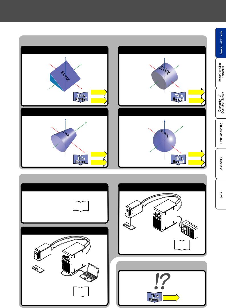
Mark on 3D Figure
Mark on Slope/Uneven 3D Figure |
Mark on Cylinder |
Z |
Z |
Y |
Y |
|
|
|
|
|
|
|
|
|
|
|
|
|
|
|
X |
|
|
|
|
X |
||||||
"Mark on Slope" |
P.77 ~ |
|
|
|
P.85 ~ |
|||||||
|
|
|
|
|
|
|
|
|||||
"Mark on Cylinder" |
|
|
||||||||||
|
|
|
|
|
|
|
|
|
|
|||
"Mark on Uneven Figure" |
|
|
|
|
|
|
|
|
|
~ |
||
|
|
|
|
|
|
|
||||||
|
|
|
P.80 ~ |
|
|
|
|
|
P.178 |
|||
|
|
|
|
|
|
|||||||
|
|
|
|
|
|
|
|
|
|
|
|
|
Mark on Cone |
|
Mark on Sphere |
Z |
Y |
Z |
|
|
Y
|
|
|
|
X |
|
|
|
|
|
|
|
|
|
|
|
|
|
|
|
|
|
|
|
|
X |
|
|
|
|
||||||
|
|
|
|
P.92 ~ |
|
|
|
|
|
P.98 ~ |
|||||||
|
|
|
|
|
"Mark on |
Sphere" |
|
|
|
|
|||||||
"Mark on Cone" |
|
|
|
|
~ |
|
|
|
|
|
|
~ |
|||||
|
|
|
|
|
P.182 |
|
|
|
|
|
|
|
P.190 |
||||
|
|
|
|
|
|
|
|
|
|
|
|||||||
Control Laser Marker from External
Check Item before Controlling from External
"Check DIP Switch"
"Check Basic Operation |
External Control |
Procedure" |
Manual |
|
|
"Set Remote Mode" |
|
Control by RS-232C
Personal
Computer
"Control by RS-232C"
"Look Through Communication
Command" External Control
Manual
"Read Description of Each 
Command"
Control by I/O
PLC
External Control
“Control by I/O” Manual
When in Trouble...
P.337
"Let's Try" Contents 13

MEMO
14 "Let's Try" Contents


 1
1
Basic Operation Procedure
1-1 When Using Laser Marker for the First Time ••••••••••••••••••• 16 1-2 Setting Procedure for Basic Function •••••••••••••••••••••••••••• 30 1-3 Basic Setting Procedure for Marking 3D Figure ••••••••••••••• 76
•This laser marker is set the operation in two ways, using both mouse and monitor and using console (option).The expression for operation "Press" in this manual means the following two actions:
When using mouse and monitor When using console (option)
"Press" on the screen means “to move the arrow toward “-” direction, and click left button of the mouse.
"Press" on the screen means to “touch “-” on the screen”.
Press
Press
Do not touch the screen with sharp-pointed object.
CHECK
*When this laser marker is set the oepration using the PC (Laser Marker NAVI plus), be sure to read and check the ”User’s Manual” referring from “HELP” on the Laser Marker NAVI plus screen.
15
1-1 When Using Laser Marker for the First Time
The procedure for using the laser marker for the first time after purchasing from performing test marking the easy character (sample show below) until turning off the power supply is described below.

 Sample
|
|
|
|
|
|
|
Character Interval: 5mm |
||||||||||||||||
|
|
|
|
|
|
|
|
|
|
|
|
|
|
|
|
|
|
|
|
|
UNX |
||
|
|
|
|
|
|
|
|
|
|
|
|
|
|
|
|
|
|
||||||
|
|
|
|
|
|
|
|
|
|
|
|
|
|
|
|
|
S |
|
|||||
|
|
|
|
|
|
|
|
|
|
|
|
|
|
|
|
||||||||
Starting |
|
|
|
|
|
|
|
|
|
|
|
|
|
||||||||||
Character |
|
|
|
|
|
|
|
|
|
|
|
|
|
|
|
|
|
|
|||||
Height: 4mm |
|
|
|
|
|
|
|
|
|
|
|
|
|
|
|
|
|
|
|
|
|
||
Coordinate |
|
|
|
|
|
|
|
|
|
|
|
|
|
|
|
|
|
||||||
|
|
|
|
|
|
|
|
|
|
|
|
|
|
|
|
|
|||||||
Character Width: 4mm |
|||||||||||||||||||||||
X: -10mm |
|||||||||||||||||||||||
|
|
|
|
|
|
|
|
|
|
|
|
|
|
|
|
|
|||||||
Y: 5mm |
|
|
|
|
|
|
|
|
|
|
|
|
|
|
|
|
|
||||||
|
|
|
|
|
|
|
|
|
|
|
|
|
|
|
|
|
|
|
|
|
|
|
|
The position and size of the character to be marked are set as follows:
Starting Coordinate X: -10mm, Y: 5mm, Laser Power: 30
Character Height: 4mm, Scan Speed: 300
Character Width: 4mm
Character Interval: 5mm

 Flow
Flow
1. Preparation of Laser Marker Operation
1.Package Check
2.Installation of laser marker
3. Connecting Laser Marker
The detail is described in "1-1-1 Preparation of Laser Marker Operation" ( P. 17).
2. Startup of Laser Marker
The detail is described in "1-1-2 Startup of Laser Marker" ( P. 18).
3.Procedure from laser marker setting to test marking
1.Set the file No. to be marked.
2.Input the character to be marked.
3.Set the marking condition.
4.Set the laser.
5.Perform test marking from console (monitor/mouse).
6.Save the setting contents.
The detail is described in "1-1-3 Procedure from Laser Marker Setting to Marking" ( P. 19).
Turn off the power of the laser marker
The detail is described in "1-1-4 Turn OFF Power of Laser Marker" ( P. 29).
16 1-1 When Using Laser Marker for the First Time
Chapter 1 Basic Operation Procedure ٛ
1-1-1 Preparation of Laser Marker Operation
1 |
Check the package. |
|
Check contents of the package of the laser marker referring to Setup Guide. |
||
If something is lack, ask for the nearest sales branch. |
||
|
|
|
2 |
Install the laser marker. |
|
Install the laser marker referring to Setup Guide. |
||
|
|
|
3 |
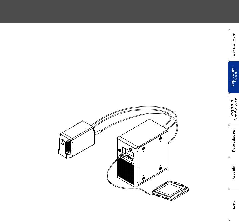
Connect the laser marker. |
|
Connect the laser marker referring to Setup Guide. |
||
(The following figure shows the connecting sample of the laser marker using the console.) |
1-1 When Using Laser Marker for the First Time 17

1-1-2 Startup of Laser Marker
1 |
Turn ON ( | ) the key switch of the controller. |
|
(Insert the system key and turn it toward ON ( | ) side. |
||
|
The main indicator flashes in green, and changes into lighted-up status after approx. 70 seconds. |
MAIN
Flash in green
Light up in green
Turn the key switch toward
ON ( | ) side.
|
|
|
Since the ON/OFF operation of the key switch puts load to laser marker, do not turn off the power |
|
|
|
supply until completing the system start. |
|
REFERENCE |
Besides, in case of turning ON the power supply after turning OFF, leave the interval at least 5 |
|
|
seconds between ON and OFF. |
||
|
|
|
|
2 |
|
The operation screen is appeared after the system is started. |
|
|
|||
18 1-1 When Using Laser Marker for the First Time

Chapter 1 Basic Operation Procedure ٛ
1-1-3 Procedure from Laser Marker Setting to Marking
a. Set the file No. to be marked.
Here describes the procedure using the sample of setting File 0003.
|
1 |
Press |
|
of the function. |
|
|
|
SETTING |
|
|
|
|
|
|
|
|
|
|
|
|
2 |
Press |
|
of the function. |
|
|
|
FILE |
|
|
|
|
|
|
|
|
|
|
|
|
3 |
Press |
|
of the function. |
|
|
|
OPEN |
|
|
|
|
|
|
|
|
|
|
|
|
The [Select File No.] window is appeared by pressing |
|||
|
|
OPEN |
. |
|
|
|
|
|
|
|
Select File No. “0003”. |
|||
4 |
||||
When pressing "0003" line, the cursor is inverted and |
||||
"0003" is selected.
5 |
Press SET . |
The file No. is set to "0003". |
1-1 When Using Laser Marker for the First Time 19

b. Input the character to be marked.
1 |
Press Character of the function. |
The screen is changed into the character setting one. |
2 |
Adjust the cursor to the first line (01) of the |
screen, and press EDIT . |
|
Re-adjusting the cursor to the first line (01), and then |
pressing (double-clicking) the same cursor performs the same operation.
3 |
Press ALPHA/NUM , and change the screen |
into alphanumeric input one. |
Here, input the character "SUNX ".
|
4 |
Press S |
|
U |
|
|
|
X |
in this order. |
|
|
|
|
|
|
|
|
N |
|
|
|
|
|
|
|
|
|
|
|
|
|
|
20 1-1 When Using Laser Marker for the First Time
Chapter 1 Basic Operation Procedure ٛ
5  Press KANA/KANJI , and change the screen into Kana input one.
6 Press .
7 |
Press |
|
|
|||||
|
||||||||
|
|
|
|
|
|
|||
|
CONVER. |
|
||||||
|
|
|
|
|
|
|
|
|
REFERENCE
, and then press
to convert into “ “.
If there exists several choosable
Kanji, press CONVER. until appropriate Kanji is appeared.
8 |
Press |
|
. |
|
COFIRM |
||||
|
1-1 When Using Laser Marker for the First Time 21

|
|
|
|
|
|
|
|
|
|
|
|
|
9 |
Press |
SET |
. |
|
|
|
|
|
|
|
|
|
|
|
|
|
The character "SUNX " is input.
22 1-1 When Using Laser Marker for the First Time
Chapter 1 Basic Operation Procedure ٛ
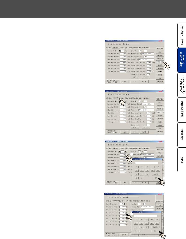
3. Set the marking condition.
Here describes the procedure for setting marking conditions using the following sample, character height: 4mm, character width: 4mm, X coordinate: -10mm, Y coordinate: 5mm, and character interval: 5mm.
1 |
Press |
|
on the function. |
|
CONDITION |
||||
|
2 |
Press |
|
. |
|
CHARACTER |
||||
|
3 |
Set “4mm” to [Character Height]. |
|
|
||||
|
|
||||||
Pressing the setting value of the [Character |
|
|
|||||
|
Height] displays the template. Press |
4 |
|
and |
1 |
||
|
|
SET |
in this order. |
|
|
|
|
|
|
|
|
||||
 2
2
4 |
Set “4mm” to [Character Width]. |
|||||
Pressing the setting value of the [Character |
||||||
|
Width] displays the template. Press |
4 |
and |
|||
|
|
SET |
in this order. |
|
|
|
 1
1
 2
2
1-1 When Using Laser Marker for the First Time 23

|
|
|
|
|
|
|
|
|
|
|
|
|
|
|
|
|
|
|
|
|
|
|
|
|
5 |
Set “-10mm” to [X Position]. |
|
|
|
|
|
||||
|
|
|
|
|
|
||||||
|
Pressing the setting value of the [X |
Position] |
|||||||||
|
|
displays the template. Press |
- |
|
1 |
|
0 |
|
|
||
|
|
and |
SET |
in this order. |
|
|
|
|
|
|
|
1
 2
2
6 |
Set “5mm” to [Y Position]. |
Pressing the setting value of the [Y Position] |
displays the template. Press 5 and SET in this order.
1
 2
2
7 |
Set “5mm” to [Char. Interval]. |
Pressing the setting value of the [Char. Interval] |
displays the template. Press 5 and SET in this order.
1
 2
2
8 |
Press IMAGE , and check the image |
screen for the correct one. |
24 1-1 When Using Laser Marker for the First Time

Chapter 1 Basic Operation Procedure ٛ
4. Set the laser.
Here describes the procedure for setting laser using the following conditions; laser power: 30, scan speed: 300mm/s.
1 |
Press |
|
of the function. |
|
LASER |
||||
|
2 |
Set “30” to [Laser Power]. |
|
|
|
|
|
|
|
|
|
|||
Pressing the setting value of the [Laser Power] |
1 |
|||||
|
displays the template. Press |
3 |
|
0 |
and |
|
SET in this order.
 2
2
3 |
Set “300mm/s” to [Scan Speed]. |
|
|
|
|||||
|
|
|
|||||||
Pressing the setting value of the [Scan Speed] |
|
||||||||
|
displays the |
template. Press |
3 |
|
0 |
|
0 |
1 |
|
|
and |
SET |
in this order. |
|
|
|
|
|
|
 2
2
1-1 When Using Laser Marker for the First Time 25

5. Perform test marking from console (monitor/mouse).
1 |
Set work for marking, and adjust the work distance. |
|
Set the distance from the bottom face of the head scanning unit to |
||
|
the surface of the work for marking with the following values: |
|
|
LP-Z130: 190mm, LP-Z250: 190mm, LP-Z256: 330mm |
|
|
It is easy to adjust the work distance using the dual |
|
|
pointer described in "2-5-2 Dual Pointer" ( |
P. |
|
REFERENCE 117). |
|
|
|
Work for Marking |
2 |
Press IMAGE of the function. |
|
The image of the character to be marked is |
|
|
displayed.
3 Press
CHECK
GUIDE of the function.
When marking on 3D figure, check the marking content using “3D View Screen” ("2- 13-3 3D View Screen" ( P. 298))‚ and perform guide indication of the marking character before marking. When the marking content is displayed within the figure area, start the marking.
4 |
Select Marking Character and press START of the |
function. |
The marking content is displayed with the guide laser.
Adjust the position of the work for marking.
26 1-1 When Using Laser Marker for the First Time
Chapter 1 Basic Operation Procedure ٛ
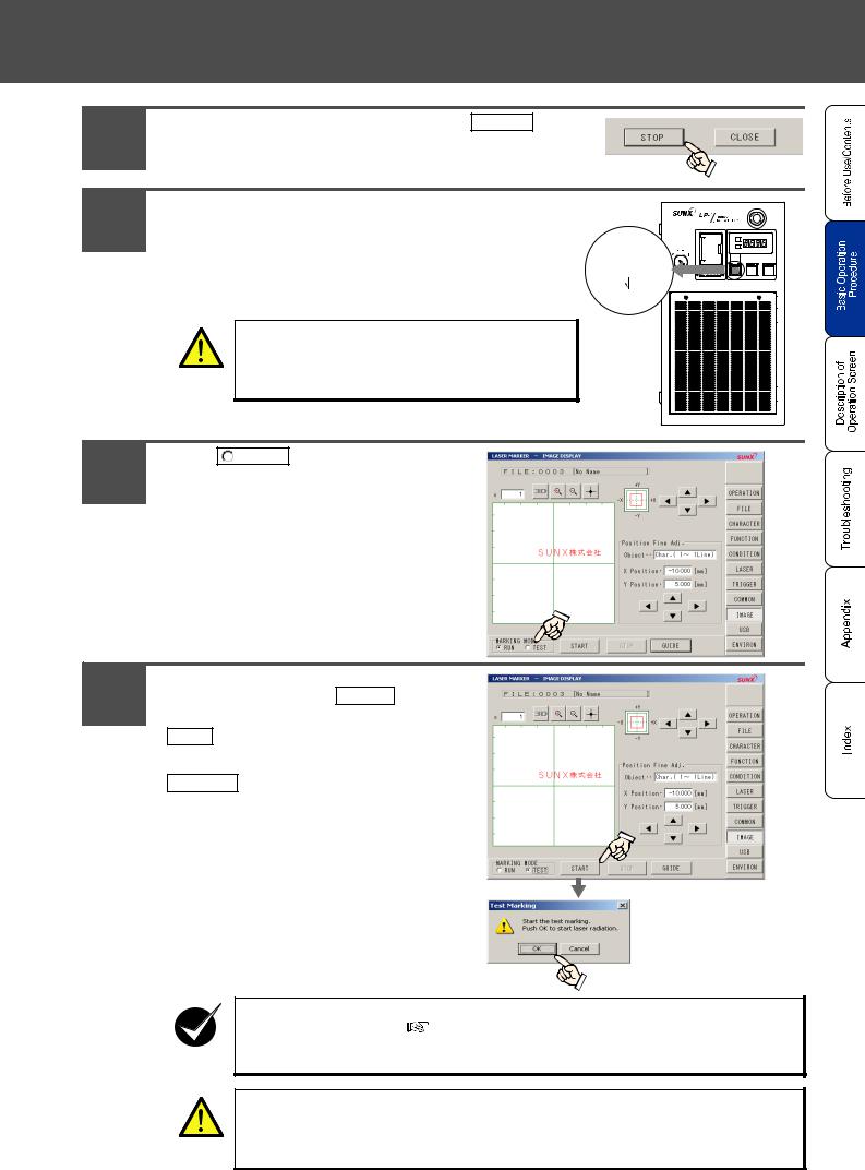
5 |
The guide laser is stopped by pressing |
STOP |
. |
|
||
|
|
|
|
|
|
|
6 |
Press the laser pumping switch on the controller. |
|
||||
After pressing the switch, check that the laser pumping switch is |
LASER |
|||||
|
changed from flashing in white (LP-Z series: approx. 20 sec.) to |
Flashing |
||||
|
(LP-Z: 20sec.) |
|||||
|
lighting up in white. |
|
|
|
||
|
|
|
|
|
||
|
After lighting up the switch in white, the laser marker is ready for |
Lighting |
||||
|
radiation. |
|
|
|
|
|
|
|
|
|
|
|
|
|
|
Be sure to use the protective goggle and enclosure |
|
|||
|
WARNING |
during dealing laser. |
|
|
|
|
|
|
|
|
|
|
|
7 |
Press |
TEST |
of the marking mode. |
|
|
|
|
|
|
|
|
|
|
8 |
The dialogue box of the test marking is |
indicated by pressing START . |
|
The marking is started by pressing |
OK .
Test marking is canceled by pressing
CANCEL .
When marking on 3D figure, check the marking content using “3D View Screen” ("2-
|
13-3 3D View Screen" ( |
P. 298))‚ and perform guide indication of the marking |
CHECK |
character before marking. When the marking content is displayed within the figure |
|
area, start the marking. |
|
|
The laser beam is emitted. Be sure to use the protective goggle and enclosure.
WARNING
1-1 When Using Laser Marker for the First Time 27

6. Save the setting contents.
Here describes the procedure for saving the condition of the file set into the main body of the laser marker.
1 |
Press |
|
of the function. |
|
FILE |
||||
|
2 |
Press the character string of the |
|
Comment. |
3 |
Input the comment, and press |
|
. |
|
SET |
||||
|
|
|
|
Both alphabet including capital and |
|
|
|
|
|
small letters and numeric can |
|
|
|
|
|
switch between singleand double- |
|
|
|
REFERENCE |
byte. Up to 20 characters can be |
|
||
|
input in case of inputting all single- |
|
|||
|
|
|
byte letter. |
|
|
|
|
|
|
|
|
|
|
|
|
|
|
4 |
Press |
SAVE |
. |
||
The file content is saved. |
|||||
The file is not saved only by inputting file name. For saving the
CHECK file, be sure to overwrite the file.
28 1-1 When Using Laser Marker for the First Time

Chapter 1 Basic Operation Procedure ٛ
1-1-4 Turn OFF Power of Laser Marker
1 |
Turn OFF the key switch (O). |
Turn the key to OFF (O) side, and pull it out. |
The main indicator is off.
Turn the key to the left, and pull it out.
When not using the laser marker, pull out the key switch and store it under the control of the manager in charge of controlling the laser marker.
If turning off the power of the laser marker without overwriting the file under dealing, the data is not saved. Be sure to check the file saving before turning off the power.
CHECK Do not turn off the power during marking. Turning off the power during marking might cause the failure of the laser marker. If it needs to stop the laser radiation immediately, press the emergency stop button.
1-1 When Using Laser Marker for the First Time 29

1-2 Setting Procedure for Basic Function
The setting method for function to be applied to the actual marking is described in this section using sample.
1-2-1 Mark Counter

 Sample
0001 |
|
0002 |
|
0003 |
... |
0998 |
|
0999 |
|
1000 |
|
0001 |
|
0002 |
|
|
|
|
|
|
|
|
|
|
|
|
|
|
|
Set the counter shown above.

 Flow
Flow
1. Set the counter.
The detail is described in " 1. Set the counter." ( P. 31).
2. Set the counter.
The detail is described in " 2. Input the counter function character." ( P. 33).
3. Set the conditions of the function character of the counter and laser.
Refer to " 3. Set the marking condition." (  P. 23) and " 4. Set the laser." (
  P. 25) described in "1-1-3 Procedure from Laser Marker Setting to Marking" (
 P. 19), "2-9 Marking Condition" (
  P. 170), and "2-10 Laser Setting" (
  P. 270) for setting each condition.
30 1-2 Setting Procedure for Basic Function
Loading...