


For speed control of 3-phase induction motor
Inverter M1X Series
Operating Instructions
Be sure to provide the customer with a copy of this manual.
●Thank you for purchasing a Panasonic Inverter.
●Be sure to read the instructions thoroughly before attempting to operate the inverter. After reading, be sure to keep in a safe place for future reference.
Industrial and Appliance Motor Division, Motor Company
Matsushita Electric Industrial Co., Ltd

CONTENTS
Before use
Safety Precaution Introduction
●When unpacking
●Inverter model check
Preparation and adjustment
System Configuration
●Wiring general view
●Wiring
●Terminal function
●Precautions when wiring
If necessary
Protective Function
●Protective functions
●Method of resetting trip
Application
Detailed Explanation of Parameters
● Parameter functions
Specifications
Specifications Outer Dimensions
- 2 -

CONTENTS
Precautions |
Installation |
● Note the following |
● Inverter |
precautions in order to use |
|
the inverter properly |
|
Parameter Setting
● How to set
Maintenance/ |
Troubleshooting |
Inspection |
● Inspection to determine |
|
cause of problem |
Parameter Setting
●Parameter overview
●Parameter configuration and list of parameters
Before use |
|
and |
Adjustment |
Preparation |
|
|
|
|
|
|
|
|
|
|
|
Ifnecessary |
|
Application |
|
Specifications |
|
|
|
- 3 -
Safety Precautions
Precautions that must be heeded in order to protect the user and others from harm and prevent property loss or damage are as follows:
■The extent of injury or damage that could be suffered by improper use contrary to directions is ranked and explained as follows:
DANGER |
Situation involving danger which could result in death or serious |
injury if equipment is handled incorrectly. |
|
|
|
CAUTION |
Situation involving danger which could result in medium to light |
injury, or property damage if equipment is handled incorrectly. |
|
|
|
Items labeled as CAUTION could be connected with core serious consequences, depending upon the circumstances. In any case, these instructions are extremely important and should be observed in all cases.
■ Installation
CAUTION
●Install on non-combustible material such as metal.
Failure to do so could result in fire.
●Do not locate near combustibles.
Doing so could result in fire.
●Do not carry by the front case when moving the inverter.
Doing so is dangerous and could result in injury if dropped.
●Do not allow foreign material such as metal chips to get inside the inverter. Doing so could result in fire.
●Be sure to install on a base capable of supporting the inverter’s weight in accordance with the directions giving in the instruction manual.
Doing so is dangerous and could result in injury if dropped.
- 4 -
Safety Precautions
■ Wiring
DANGER
●Make sure the power is cut off before handling wiring. Failure to do so could result in electrical shock or fire.
●Be sure to install a no-fuse breaker (NFB).
Failure to do so could result in fire.
●Be sure to ground the GND terminal.
Failure to do so could result in electrical shock or fire.
●Have wiring work done by an electrician.
Failure to do so could result in electrical shock or fire.
●Be sure to install the inverter before wiring.
Failure to do so could result in electrical shock or fire.
CAUTION
●Do not connect the AC power source with the output terminals (U/L1, V/L2, W/L3).
Doing so could result in injury or fire.
●Make sure the voltage of the AC power source agrees with the rated voltage of the inverter.
If not, it could result in injury or fire.
- 5 -
Safety Precautions
■ Operation
DANGER
●Be sure to mount the case and cover before turning the power on. Never remove the case or cover while the inverter is receiving power.
Failure to mount or removing the case/cover could result in electric shock.
●The operator should secure the area before turning the power on or off. Failure to do so could result in injury.
●Never operate the switches with wet hands.
Doing so could result in electric shock.
●Never touch the terminals of the inverter when it is charged with power, even when it is not running. Doing so could result in electric shock.
●If the retry function is selected, the inverter could unexpectedly start operating again if tripped. Do not approach the inverter in the condition.
Doing so could result in injury.
●If trip reset is carried out with the operate signal ON, the inverter could unexpectedly start operating again. Do not approach the inverter in the condition. Doing so could result in injury.
CAUTION
●The radiator and regenerative resistor become very hot.
Touching these parts could result in skin burning injury.
●It is very easy to set speed from "low" to "high" by an inverter. Set the operating speed so that it the motor and machine tolerance is not exceeded.
Failure to do so could result in injury.
- 6 -
Safety Precautions
■Maintenance/inspection
DANGER
●Wait for at least 5 minutes after turning off the power to perform inspections. Failure to do so could result in electric shock.
●Maintenance and inspection should not be performed by anyone except a specialist.
The repairman should remove all metallic objects (watch, rings, etc.) before performing maintenance or inspection.
Use only insulated tools when performing maintenance or inspection. Failure to do so could result in electric shock or injury.
■Other
DANGER
●Absolutely DO NOT modify the inverter in any way.
Doing so could result in electric shock, injury or fire.
GENERAL PRECAUTIONS
The diagrams given in this instruction manual may show the cases, covers or safety breakers removed in order to show details.
When operating, be sure to return the cases, covers or safety breakers and operate as specified in the manual.
- 7 -
Introduction
When unpacking
Is the model correct?
Was the equipment damaged in transport?
If there is anything wrong with the equipment, contact your Panasonic dealer.
Inverter model check
Nameplate
|
|
MIXA54ASA |
|
Model No |
|||
Power |
15kW |
|
|
Input |
3PH AC 380 460V |
50/60Hz |
|
|
37A |
|
|
Output |
3PH AC 380 460V |
0 400Hz |
|
|
32A |
|
|
Ser.No. 9903012
Matsushita Electric Industrial Co., Ltd. Made in Japan
Product No.

 A
A 


 B
B 


Series name
Code |
Interface specs. |
AWithout communication function/ standard type (NPN logic)
CWith communication function/ standard type (NPN logic)
Code |
Motor capacity |
|
|
|
|
|
|
|
||
|
|
|
|
|
|
|
|
|
|
|
08 |
0.75 kW |
|
|
|
|
|
|
|
|
|
|
|
|
|
|
Code |
Operation panel specs. |
||||
15 |
1.5 kW |
|
|
|
|
|
||||
|
|
|
|
|
|
|
|
|||
22 |
2.2 kW |
|
|
|
|
|
|
|
|
|
|
|
|
|
|
S |
Without set volume (standard) |
||||
37 |
3.7 kW |
|
|
|
|
|
||||
|
|
|
|
|
V |
With speed-set volume |
||||
55 |
5.5 kW |
|
|
|
|
|
||||
|
|
|
|
|
N |
Blank cover |
||||
75 |
7.5 kW |
|
|
|
|
|
||||
A1 |
11 kW |
|
|
|
|
|
|
|
|
|
|
|
|
|
|
|
|
|
|||
A5 |
15 kW |
|
|
|
Code |
Regenerative brake specs. |
|
|||
|
|
|
|
|
|
|
|
|||
|
|
|
|
|
A |
Without regenerative brake circuit |
|
|||
Code |
Voltage class |
|
|
|||||||
|
|
|
|
|
B |
With regenerative brake circuit (built-in) |
|
|||
4 |
3-phase |
400 V |
||||||||
|
|
|
|
|
|
|||||
|
|
|
|
|
|
|||||
|
|
|
|
|
|
|
|
|
|
|
Consult your Panasonic dealer regarding products with communication functions.
- 8 -

Precautions
Note the following precautions in order to use the inverter properly.
1.Arrange for the power source capacity to be between 1.5 to 500kVA the inverter's capacity. An excessively high peak current may flow to the power input circuit, and damage the converter section if the wiring length is short with a power source exceeding 500kVA, or the phase-advancing capacitor is switched on the power source side. In this case, provide individual power factor-enhancing AC reactors that match the inverter's capacity on the inverter input side.
2.Do not connect the phase-advancing capacitor to the output side of the inverter. Doing so could result in damage to the phase-advancing capacitor.
3.Do not provide a magnetic contactor between the inverter and motor. To run or turn the motor on/off, use the RUN switch on the control panel or the control input terminal.
Avoid frequently turning the magnetic contactor, provided on the power source, on and off.
4.Operating the motor by the inverter could increase leakage current and trip the earth leakage breaker. In this case, use earth leakage breakers designed for high frequency for this system and other systems.
5.Take the following precautions if using a built-in electronic thermal relay contained in the inverter:
Check the rated current of your 3-phase induction motor, and set the appropriate electronic thermal value.
Use one motor for each inverter.
6.in using the inverter to drive multiple motors connected in parallel, select an inverter of a capacity that does not exceed the total rated current of the inverter. When calculating by total output of the motor, the inverter’s rated current may be exceeded, depending on the type of motor.
7.The total wiring length between inverter and motor should not exceed 30 meters. If the wiring is to be longer than this, you should provide a reactor, etc., between inverter and motor.
8.Install the inverter securely to avoid injuries in the case of an earthquake.
9.Before running the inverter following an earthquake, check installation of the inverter and motor and make sure they are safe to operate.
-9 -
Installation
Install the inverter properly to prevent equipment failure or accidents.
Inverter
Installation location
Install the inverter indoors in a place not exposed to rain or direct sunlight. The inverter is not waterproof.
Install in a place not exposed to corrosive/flammable gases, grinding fluid, oil mist, metal powder or chips.
Place with adequate ventilation, which is not exposed to excessive humidity, dirt or dust.
Place not subject to vibration.
Environmental conditions
Item |
Conditions |
Ambient temperature |
10 50 (Must not freeze) |
When ambient temperature is higher than +40 , the air |
|
|
apron and the linear rubber apron should be disassembled |
Ambient humidity |
Max. 90%RH Must be no condensation |
Storage temperature |
20 65 (Must not freeze) |
Storage humidity |
Max. 90 %RH Must be no condensation |
Vibration |
Max. 5.9 m/s2 10 60 z |
Elevation |
Max. 1000 m |
* Short-term temperature during transport
Mounting direction and clearance
Provide sufficient clearance for effective cooling.
|
|
|
|
|
Min. 200 mm |
||
30 mm |
Upper |
|
Upper |
|
Upper |
30 mm |
|
|
|
|
|
|
|||
× |
M1X |
|
M1X |
|
M1X |
× |
|
|
|
|
|
||||
Min. |
|
Min. |
|
Min. |
|
Min. |
|
Lower |
50 mm |
Lower |
50 mm |
Lower |
|||
100 mm |
100 mm |
||||||
|
|
|
|
|
|||
|
|
|
|
|
Min. |
|
|
|
|
|
× 30 mm |
100 mm |
|||
|
|
|
|
|
|||
Make sure ambient temperature doesn’t exceed allowable temperature at position indicated by X in the figure above.
- 10 -
System Configuration and Wiring
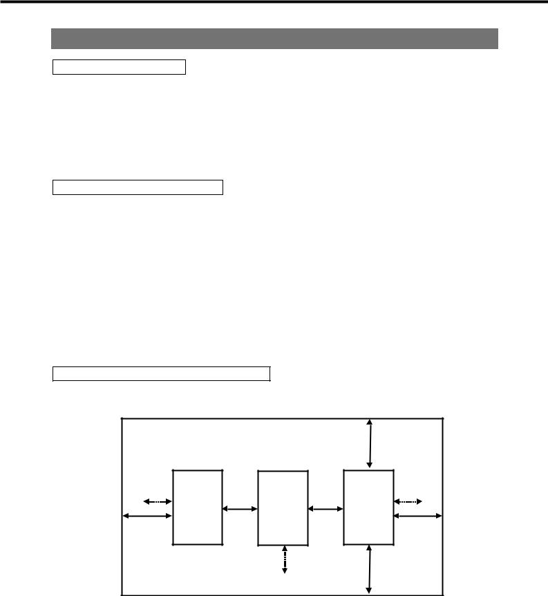
Wiring general view
Main circuit
Inverter
GND
Motor
No-fuse breaker (NFB) or Earth leakage breaker
Used to protect the power line.
Interrupts the circuit in the case of excessive current.
Noise filter (NF)
Blocks noise from the power line.
Also reduces effect of noise from the servomotor.
Magnetic contactor (MC)
Turn main power to servomotor on/off.
Used with surge absorber mounted.
Reactor (L)
Reduces harmonic current of the power source.
DC reactor
- 11 -

System Configuration and Wiring
Wiring
Standard wiring diagram
External feedback resistor (5.5 kW-11kW only)
Those lower than 3.7 kW and 15Kw have no terminals for feedback resistor
NFB |
|
|
|
PB |
|
Power source 3-phase |
|
R/L1 |
U/T1 |
||
|
|
|
|||
AC380 460V |
|
S/L2 |
|
|
V/T2 |
50/60Hz |
|
T/L3 |
|
|
W/T3 |
External frequency setting volume |
|
|
|
|
|
FIN1 |
|
|
|
||
1/4W, 5kΩ , B characteristic |
|
|
|
|
|
Frequency meter |
|
|
|
|
|
|
FOUT |
|
|
||
1mA (full scale) |
|
|
|
||
|
|
|
|
|
|
|
|
|
|
|
|
|
|
|
|
|
|
|
|
12V |
|
|
COM1 |
|
Note1) |
|
|
|
|
|
PLC |
|
|
|
|
|
|
|
|
|
|
Forward/stop switch |
|
|
|
|
|
Reverse/stop switch |
|
|
|
|
|
Frequency setting selection (1) |
|
|
|
|
|
Frequency setting selection (2) |
|
|
|
|
|
Free-run |
|
|
|
|
|
Trip reset* |
|
|
|
|
COM2 |
Ground for control |
|
|
|
|
|
Be sure to provide proper treatment |
|
(Frame ground) |
|
||
for the shielded wire terminals. |
|
|
|
|
|
Motor
IM
(Collector) trip output*
(Collector) Reach-signal*
(Emitter)
VCE max.=DC24V IC max.=50mA
Trip signal Contact capacity
AC30V 2A
DC30V 2A
GND terminal
Be sure to ground
Asterisk (*) indicates factory-set function.
Note 1) PLC terminals and 12V terminals connected, it is called synchronized input circuit.
PLC terminals and G terminals connected, it is called power input circuit.
- 12 -
System Configuration and Wiring
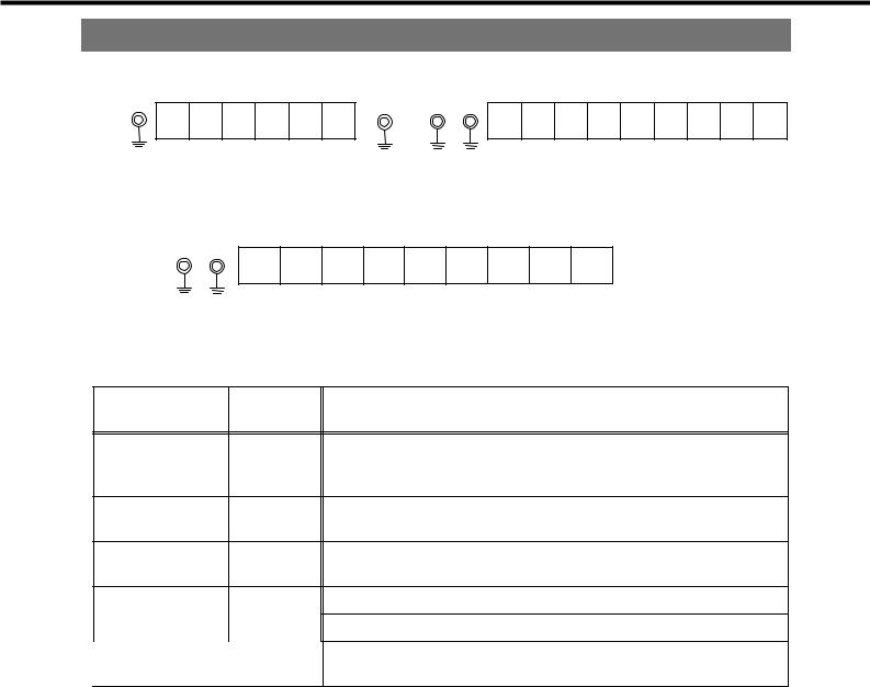
Terminal function
(1) Main circuit terminal |
|
Not used |
|
|
|
↓ |
|
R/L1 S/L2 T/L3 U/T1 V/L2W/L3 |
|
R/L1 S/L2 T/L3 PB |
U/T1 V/T2W/T3 |
750W 3700W |
|
5.5 W |
|
Not used |
|
|
|
|
↓ |
|
|
R/L1 S/L2 T/L3 |
N |
U/T1 V/T2 W/T3 |
|
5
Terminal No. Terminal
name
Power R/L1, S/L2, T/L3 source input
terminal
U/T1, V/T2, W/T3 Outputterminal
EGND terminal
P |
P terminal |
N |
N terminal |
|
|
PB |
PB terminal |
|
|
Function description
Connect to commercial power source (3-phase 380-460V 50/60 Hz)
Connect to 3-phase induction motor
Terminal for grounding inverter base
(+) terminals for the recitification part
(-) terminals for the recitification part
Terminals for external feedback resistor. Connect the resistor between P and PB.
- 13 -

System Configuration and Wiring
(2) Control terminal |
|
|
|
|
|
|
|
|
|
|
|
|
|
|
|
|
|
|
|
|
|
|
|
|
|
|
|||
|
|
|
|
|
|
|
|
|
|
|
|
|
|
|
|
|
|
|
|
|
|
|
|
|
|
|
|
|
|
|
|
|
|
|
|
01 |
02 |
|
F1N1 |
F1N2 |
FOUT |
|
I2 |
|
I4 |
|
I6 |
|
12V |
|
|||||||||
|
COM2 |
NC |
|
NO |
|
|
COM1 |
|
12V |
PLC |
G |
I1 |
|
I3 |
|
I5 |
|
G |
|
5V |
|||||||||
Terminal No. Terminal name 

|
|
|
Power source |
|
|
|
terminal for fre- |
|
|
|
quency setting |
|
|
External power |
|
|
terminal |
||
|
|
|
|
|
|
|
|
|
|
Input terminal |
|
|
|
for frequency |
|
|
setting |
||
|
|
|
|
|
|
|
Ground for |
|
|
control |
|
|
|
|
|
|
|
|
|
|
|
Frequency |
|
|
meter terminal |
||
|
|
|
|
|
|
|
|
|
|
|
Forward/stop |
|
|
|
command |
|
|
|
terminal |
|
|
|
Reverse /stop |
|
|
|
command |
terminal |
|
|
terminal |
|
|
Frequency |
|
|
|
||
Input |
|
|
|
|
setting |
||
|
|
||
|
|
|
|
|
|
|
selection |
|
|
terminal |
|
|
|
|
|
|
|
|
|
|
|
|
|
|
|
|
Ground for |
|
|
control |
|
|
|
|
|
|
|
|
|
terminal |
|
|
Output signal |
|
terminal |
||
|
COM1 |
||
|
|
||
|
|
|
|
Output |
|
|
|
|
|
Output signal |
|
|
|
|
|
|
|
COM |
terminal |
|
|
|
|
|
|
|
|
Function description
+5VDC applied.
+12VDC applied.
The common terminal used for contact input of external power is used. When power is on (PLC and G connected), a closed terminal in ON, and an open one, OFF
Frequency can be set when 0 ~ +5VDC (or 0 - +10VDC) is input between “FIN1” and “G”, or 4-20mA between "FIN2"-G. If both are input, the bigger will be pick up.
If using these terminals, change “ frequency command” to


 or
or 


 .
.
Common ground terminal for contact input. The common terminal used for contact input of synchronized input is used. When power is on (PLC and 12V connected), a closed terminal in ON, and an open one, OFF.
Outputs voltage proportional to output frequency between “FOUT” and “G.” Connect full-scale 1 mA DC ammeter. You can output pulses synchronized with output frequency by altering “ FOUT switch”.
Forward by shorting between “I1” and “G”; stop by release Reverse by shorting between “I2” and “G”; stop by release
You can change “I1” to run/stop command and “I2” to forward/reverse command by altering“ I1.12” function selection.
You can select the following functions in operation mode.
Operation mode |
I3 |
I4 |
|
I5 |
|
2-speed operation mode |
Forward |
Reverse |
Select from among |
||
|
jogging |
jogging |
free-run, external forced |
||
4-speed operation mode |
|
|
|
trip, No. 2 acceleration/ |
|
|
Frequency setting |
|
|
deceleration, trip reset |
|
8-speed operation mode |
|
|
|||
selection |
|
|
|
|
|
16-speed operation mode |
|
|
|
|
|
|
|
|
|
|
|
Contact input common ground terminal.
Open-collector output terminal. (Not maintained when power is OFF.) You can select contents by “ output signal (1) selection.”
Factory setting: “01” is trip signal (transistor ON when tripped) “O1” (collector) IC max. = 50mA
“C1” (emitter) VCE max. = 24VDC
Relay output terminal. 30VDC 1A (max.) (Not maintained when power is OFF.)
You can select output contents by “ relay output polarity selection.” Not built-in to products without regenerative brake circuit.
- 14 -
System Configuration and Wiring
Precautions when wiring
Main circuit
(1)The inverter will be damaged if you invert the connections of the power input terminal and motor output terminal (U/L1, V/L2 ... W/L3). Absolutely do not invert connections.
(2)Do not ground the main circuit terminal.
(3)Do not short motor output terminals (U/L1, V/L2 ... W/L3) together.
(4)The GND terminal (E) is the frame ground (FG) for the inverter.
(5)Be sure to use insulated crimp terminals for connecting to the main circuit terminals.
Control circuit
(1)Do not apply more than 24VDC, 50mA to the output terminals (O1, O2, COM1), or apply voltage to terminal in reverse.
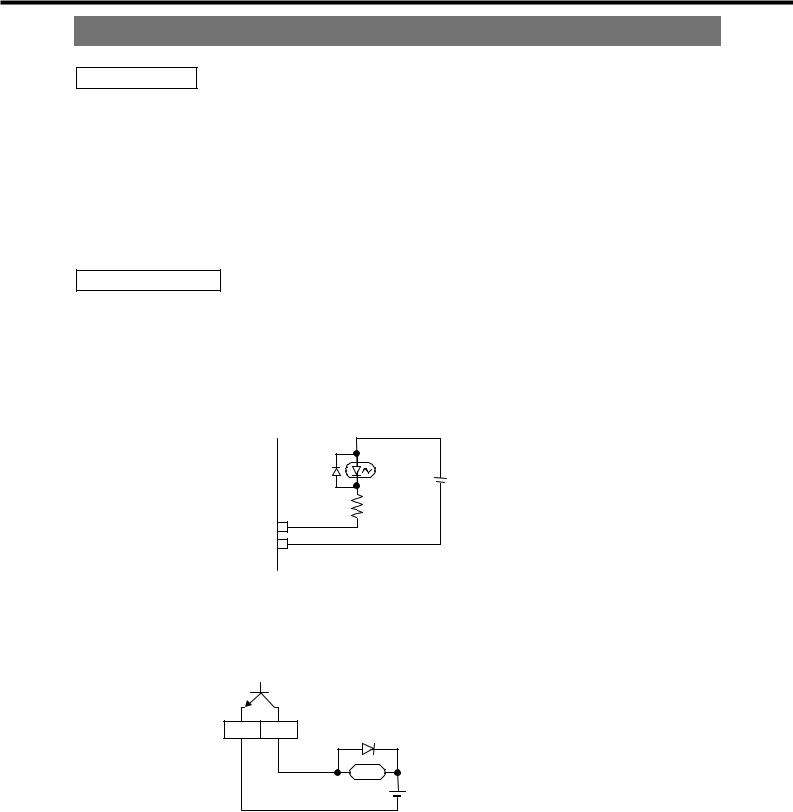
(2)Input terminal configuration is shown in the following figure.
You can control by contact or by open collector output. Do not apply external voltage.
Internal circuits are as follows:
Photo coupler |
I1 I6
GND
Inverter internal power source +12V
(3)Do not short the frequency setting power source terminal (5V) and ground for control terminal (G).
(4)To directly drive the relay by the output terminals (O1, O2, COM), mount a flywheel diode (FD).
1 |
|
|
|
|
O |
/ |
|
|
|
|
|
|
<Examples> |
Fuji Electric ERA15-01 |
|
|
|
|
ERB12-01 |
Pay attention to polarity of diode.
(5)Use shielded wires for the cable to be connected to the control circuit.
-15 -
 Loading...