


B410/B420/B430/MPS420b
Maintenance Manual
080409B
Oki Data CONFIDENTIAL

Copyright © 2008 by Oki Data. All Rights Reserved
Oki Data America's, Inc. ("Oki Data"), authorizes you to view, copy, and print documents published by Oki Data for noncommercial use within your organization only. In consideration of this authorization, you agree and acknowledge that any copy of these documents shall retain all copyright and proprietary rights contained herein. Each document published by Oki Data may contain additional copyright information and proprietary notification relating to that individual document.
Nothing contained herein shall be construed as conferring by estoppel, implication or otherwise any license or right under any patent or trademark of Oki Data, Oki Electric Industry Co., Ltd. ("Oki Electric"), or any third party. Except as provided above nothing contained herein shall be construed as conferring any license or right under any Oki Data copyright.
Oki Data has taken care to insure that the information which follows is complete, accurate and up-to-date. However, Oki Data assumes no responsibility for errors or omissions which may occur. All the information provided is subject to change from time to time at the sole discretion of Oki Data.
All publications may include technical inaccuracies or typographical errors. We reserve the right to make periodic changes, additions, and deletions to publications without notice.
The most up-to-date drivers and manuals are available from the web site: http://www.okiprintingsolutions.com
Oki Data CONFIDENTIAL

Oki Data CONFIDENTIAL |
PREFACE |
|
|
|
|
PREFACE
This Maintenance Manual describes the maintenance methods in the printer field for the maintenance personnel. In addition, regarding the handling and operating method of the printer, please refer to the "User’ s Manual".
The differences between various types of printers described in this Maintenance Manual are as follows.
|
|
B410d |
B410dn |
B420dn |
B430d |
B430dn |
|
|
Engine speed (letter/A4) |
30/28 |
30/28 |
30/28 |
30/28 |
30/28 |
|
||
Resolution |
Max. |
2400 x 600 |
2400 x 600 |
2400 x 600 |
1200 x 1200 |
1200 x 1200 |
|
|
resolution |
dpi |
dpi |
dpi |
dpi |
dpi |
dp |
||
|
||||||||
|
Standard |
PCL6/SIDM |
PCL6/SIDM |
PCL6/SIDM |
PCL6/PS3/ |
PCL6/PS3/ |
PCL6/PS3/ |
|
Emulation |
SIDM |
SIDM |
SIDM |
|||||
|
|
|
|
|||||
|
Option |
N/A |
N/A |
N/A |
N/A |
N/A |
N/A |
|
|
LCD |
16 character x 16 character x 16 character x 16 character x 16 character x 16 character x |
||||||
Operation |
display |
2 |
2 |
2 |
2 |
2 |
2 |
|
|
1 (online/ |
1 (online/ |
|
|
|
|
||
panel |
Switch |
6 |
6 |
6 |
6 |
|||
offline) |
offline) |
|||||||
|
|
|
|
|
|
|||
|
LED lights |
2 |
2 |
2 |
2 |
2 |
2 |
|
|
|
Single sheet |
Single sheet |
50 sheets |
50 sheets |
50 sheets |
50 sheets |
|
Input tray (Manual/Auto) |
Multi Purpose |
Multi Purpose |
Multi Purpose |
Multi Purpose |
||||
manual feed |
manual feed |
|||||||
|
|
Feeder |
Feeder |
Feeder |
Feeder |
|||
|
|
|
|
|||||
Input tray (1st bin) |
250 sheets |
250 sheets |
530 sheets |
250 sheets |
250 sheets |
530 sheets |
||
Maximum Input capacity |
781 |
781 |
1110 |
830 |
830 |
1110 |
||
|
USB 2.0 |
|
|
|
|
|
|
|
Interface |
Parallel |
|
|
|
|
|
|
|
|
Ethernet |
N/A |
|
|
N/A |
|
|
|
Auto Duplex |
Standard |
Standard |
Standard |
Standard |
Standard |
Standard |
||
Monthly Duty |
Maximum |
50,000 pages |
50,000 pages |
70,000 pages |
70,000 pages |
70,000 pages |
70,000 pages |
|
Cycle |
||||||||
|
|
|
|
|
|
|
||
|
|
|
3,500 (7,000 |
3,500/7,000/ |
|
|
3,500/7,000/ |
|
Toner life@ISO19752 |
3,500 |
available for |
3,500/7,000 |
3,500/7,000 |
||||
10,000 |
10,000 |
|||||||
|
|
|
JPN only) |
|
|
|||
|
|
|
|
|
|
|
||
Dimensions |
Width |
14.5”/369mm |
14.5”/369mm |
14.5”/369mm |
14.5”/369mm |
14.5”/369mm |
|
|
Depth |
15.6"/395mm |
15.6"/395mm |
15.6"/395mm |
15.6"/395mm |
15.6"/395mm |
|
||
(inch./mm) |
|
|||||||
Height |
10.6"/268mm |
10.6"/268mm |
11.7"/297mm |
10.6"/268mm |
10.6"/268mm |
|
||
|
|
|||||||
|
ODA 100v |
|
|
|
N/ |
|
|
|
|
ODA 200v |
|
|
|
N/A |
|
|
|
Sales |
OEL |
|
|
N/A |
|
|
|
|
AOS 1byte |
|
|
N/A |
|
|
|
||
Territories |
|
|
|
|
|
|||
AOS 2byte |
|
|
N/A |
|
|
|
||
|
|
|
|
|
|
|||
|
Japan |
N/A |
|
N/A |
N/A |
|
|
|
|
China |
TBD |
TBD |
TBD |
TBD |
TBD |
|
|
Note! • It is prohibited to reprint entire or partial of the content without prior consent. |
||||||||
• For the reason of printer improving and manual content revising, the content of this |
||||||||
|
maintenance manual may change without any warning in the future. |
|
||||||
43984801TH Rev.1 |
|
|
|
|
|
/ |
||

|
|
Contents |
Oki Data CONFIDENTIAL |
|
|
|
Contents |
|
1. CONFIGURATION........................................................................................................ |
7 |
|
1.1 |
System Configuration ............................................................................................................................. |
7 |
1.2 |
Printer Configuration............................................................................................................................... |
8 |
1.3 |
Optional Configuration.......................................................................................................................... |
11 |
1.4 |
Specification.......................................................................................................................................... |
12 |
1.5 |
Printing display...................................................................................................................................... |
15 |
1.5.1 VCCI label, Serial No. label............................................................................................................. |
15 |
|
1.5.2 Warning label.................................................................................................................................. |
15 |
|
1.5.3 Warning / Caution display............................................................................................................... |
16 |
|
2. Operational explanation.............................................................................................. |
17 |
|
2.1 |
Electrophotographic process mechanism ............................................................................................ |
17 |
2.2 |
Printing process.................................................................................................................................... |
24 |
2.3 Toner entrance detection....................................................................................................................... |
28 |
|
3. Parts replacement....................................................................................................... |
30 |
|
3.1 |
Preparation for parts replacement......................................................................................................... |
30 |
3.2 |
Parts layout........................................................................................................................................... |
32 |
3.3 |
Parts replacement method.................................................................................................................... |
37 |
3.3.1 LED Head....................................................................................................................................... |
38 |
|
3.3.2 Roller-Transfer................................................................................................................................. |
39 |
|
3.3.3 Cover-Side-R.................................................................................................................................. |
40 |
|
3.3.4 Cover-Side-L................................................................................................................................... |
41 |
|
3.3.5 CU Board........................................................................................................................................ |
42 |
|
3.3.6 Motor-DC-Main .............................................................................................................................. |
43 |
|
3.3.7 OPE Cover-Assy............................................................................................................................. |
44 |
|
3.3.8 Ope-Board...................................................................................................................................... |
45 |
|
3.3.9 MPT-Assy (In case of B410dn, it is Manual-Assy).......................................................................... |
46 |
|
3.3.10 Front-Guide-Assy.......................................................................................................................... |
47 |
|
3.3.11 Roller-Assy-Feed.......................................................................................................................... |
48 |
|
3.3.12 Guide-Paper-Duplex..................................................................................................................... |
49 |
|
3.3.13 Stacker-Cover-Assy...................................................................................................................... |
50 |
|
3.3.14 Fuser-Assy.................................................................................................................................... |
51 |
|
3.3.15 Rear-Cover-Assy........................................................................................................................... |
53 |
|
3.3.16 Frame-Assy-Lower........................................................................................................................ |
54 |
|
3.3.17 High voltage / Low voltage power board....................................................................................... |
56 |
|
3.3.18 Plate-Bracket-Motor...................................................................................................................... |
57 |
|
3.3.19 Roller-Back up............................................................................................................................... |
58 |
|
3.3.20 Roller-Resist................................................................................................................................. |
59 |
|
3.3.21 Lever-In-Sensor............................................................................................................................ |
60 |
|
3.2.22 Lever-Eject-Sensor/Photo-Interrupter........................................................................................... |
61 |
|
3.3.23 Lever-End/Lever-Duplex/Lever-Cassette/Gear-Assy-Clatch......................................................... |
62 |
|
3.3.24 Paper feeding roller (Roller-Pick-Up,Roller-Feed-NOW,Roller-Assy-MPT)................................... |
64 |
|
43984801TH Rev.1 |
/ |
Oki Data CONFIDENTIAL |
Contents |
|
|
|
|
4. ADJUSTMENT............................................................................................................ |
66 |
|
4.1 |
Category and function of maintenance mode....................................................................................... |
66 |
4.4.1 User maintenance mode (Administrator Menu) ............................................................................. |
66 |
|
4.1.2 System maintenance mode (System maintenance menu)............................................................. |
71 |
|
4.1.3 Engine maintenance mode............................................................................................................. |
76 |
|
4.1.4 Environment mode setting.............................................................................................................. |
84 |
|
4.1.5 EEPROM Initialization..................................................................................................................... |
85 |
|
4.2 |
Adjustment at part replacement............................................................................................................ |
86 |
4.2.1 EEPROM data upload / download method..................................................................................... |
86 |
|
5. Periodic Maintenance.................................................................................................. |
87 |
|
5.1 |
Periodic Replacement Parts.................................................................................................................. |
87 |
5.2 |
Cleaning................................................................................................................................................ |
87 |
5.2.1 Cleaning of LED lens array............................................................................................................. |
87 |
|
5.2.2 Cleaning Page Function.................................................................................................................. |
89 |
|
6. Procedures for Repairing............................................................................................ |
90 |
|
6.1 Troubleshooting..................................................................................................................................... |
90 |
|
6.2 |
Points to be checked before modifying printing problems..................................................................... |
90 |
6.3 |
Points to be checked when the printing problems are modified............................................................ |
90 |
6.4 |
Preparation for Troubleshooting............................................................................................................ |
90 |
6.5 Troubleshooting Flow............................................................................................................................ |
91 |
|
6.5.1 LCD Status Message/ Trouble Table............................................................................................... |
91 |
|
6.5.2 LCD Message Troubleshooting..................................................................................................... |
103 |
|
6.5.3 Print Troubleshooting.................................................................................................................... |
111 |
|
7. Connection Diagram................................................................................................. |
119 |
|
7.1 |
Connection diagram............................................................................................................................ |
119 |
7.2 |
Board Layout....................................................................................................................................... |
120 |
7.3 |
Resistance value................................................................................................................................. |
134 |
Appendix A Centronics Parallel Interface..................................................................... |
136 |
|
Appendix B USB Interface............................................................................................ |
143 |
|
Appendix C Maintenance Manual for Second Tray unit................................................ |
145 |
|
1 Overview................................................................................................................................................ |
145 |
|
1.1 Function........................................................................................................................................... |
145 |
|
1.2 Exterior and Parts Name.................................................................................................................. |
145 |
|
2. Description for Operation of Second Tray unit....................................................................................... |
146 |
|
3. Part Replacement.................................................................................................................................. |
147 |
|
3.1 Precautions on replacing parts........................................................................................................ |
147 |
|
3.2 Arrangement of Parts....................................................................................................................... |
148 |
|
3.3 How to Replace Parts...................................................................................................................... |
149 |
|
|
3.3.1 Roller-Pick-Up, Roller-Feed-Now.............................................................................................. |
150 |
|
3.3.2 Guard-Connector. Connector (9715S-08Z02-G4C).................................................................. |
151 |
|
3.3.3 Roller-Feed............................................................................................................................... |
152 |
|
3.3.4 Board-OT7................................................................................................................................ |
153 |
43984801TH Rev.1 |
/ |
Oki Data CONFIDENTIAL |
Contents |
|
|
|
|
3.3.5 CONN Cord-AMP8P-AMP8P.................................................................................................... |
154 |
|
3.3.6 Gear-Assy-Clatch...................................................................................................................... |
155 |
|
3.3.7 Frame-Assy-Retard, Spring-Retard.......................................................................................... |
157 |
|
4. Cleaning of Paper Feed Roller and Separation Roller.......................................................................... |
158 |
|
5. Procedure for Troubleshooting............................................................................................................... |
159 |
|
5.1 |
Precautions for Troubleshooting....................................................................................................... |
159 |
5.2 |
Preparation before Troubleshooting................................................................................................. |
159 |
5.3 Troubleshooting Method................................................................................................................... |
160 |
|
5.3.1 LCD Status Message List......................................................................................................... |
161 |
|
6. Connection Diagram.............................................................................................................................. |
163 |
|
6.1 |
Connection diagram......................................................................................................................... |
163 |
6.2 |
Board Arrangement.......................................................................................................................... |
163 |
Appendix D Network Interface...................................................................................... |
165 |
|
43984801TH Rev.1 |
/ |
Oki Data CONFIDENTIAL |
1. CONFIGURATION |
|
|
|
|
1. CONFIGURATION
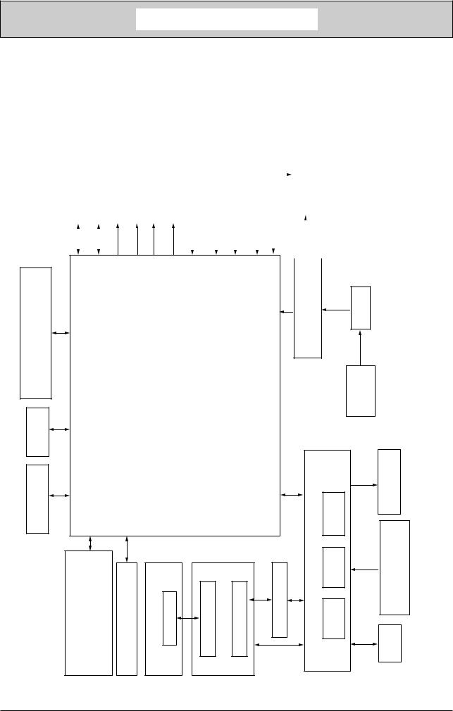
1.1 System Configuration
As the diagram 1.1 shows, for the standard configuration printer is configured by controller unit and engine unit.
|
|
|
|
|
|
Hopping clutch (1st) |
|
|
|
Hopping clutch (MPT) |
|
Solenoid for paper inverting |
|
Cassette & Duplex detecting |
|
Paper end sensor |
|
|
|
|
Rear cover open sensor |
|
|
|
|
|
|
|
|
|
|
|
|
|
|||
2nd tray unit* |
|
Main DC Motor |
|
Register clutch |
|
|
Exit sensor |
|
Fuser unit |
Halogen lamp |
|
Temperature sensor |
|
FUSE |
|
||||||||||||||||||||||
|
|
|
|
|
|
|
|
|
|
|
|
|
|
|
|||||||||||||||||||||||
|
|
|
|
|
|
|
|
|
|
|
|
|
|
|
|
|
|
|
|
|
|
|
|
|
|
|
|
|
|
|
|
|
|||||
|
|
|
|
|
|
|
|
|
|
|
|
|
|
|
|
|
|
|
|
|
|
|
|
|
|
|
|
|
|
|
|
|
|||||
|
|
|
|
|
|
|
|
|
|
|
|
|
|
|
|
|
|
|
|
|
|
|
|
|
|
|
|
|
|
|
|
|
|
|
|
|
|
|
|
|
|
|
|
|
|
|
|
|
|
|
|
|
|
|
|
|
|
|
|
|
|
|
|
|
|
|
|
|
|
|
|
|
|
|
|
|
|
|
|
|
|
|
|
|
|
|
|
|
|
|
|
|
|
|
|
|
|
|
|
|
|
|
|
|
|
|
|
|
|
|
|
|
|
|
|
|
|
|
|
|
|
|
|
|
|
|
|
|
|
|
|
|
|
|
|
|
|
|
|
|
|
|
|
|
|
|
|
|
|
|
|
LAN |
T/100BASE-TX) |
|
|
|
|
|
|
|
|
|
Low voltage |
power supply unit |
|
|
AC-SW |
|
(10BASE- |
|
|
|
|
|
print circuit board |
|
|
|
|
|
|
|
AC inlet |
|
USB 2.0 |
|
|
|
|
|
Main |
|
|
|
|
|
|
|
|
|
CENTRONICS |
|
|
|
|
|
|
|
|
|
|
supply uint |
Toner inlet |
sensor |
Transfer roller |
|
SW:1(B410d/B410dn)LED:2,LCD:1, |
LED:2,LCD:1,SW:6 |
(B420dn/B430d/B430dn) |
headLED |
cartridgeToner |
boardTag |
boardtransitTag 3 |
cartridgedrumImage |
boardtransitTag 2 |
transitTagboard 1 |
openSW |
||||
|
panelOperatorboard |
Highvoltagepower |
IN WRT |
sensor sensor |
FAN |
||||||||||
|
|
|
|
|
|
|
|
|
|
|
|
|
|
|
Stackercover |
Figure1-1
43984801TH Rev.1 |
/ |
Oki Data CONFIDENTIAL |
1. CONFIGURATION |
|
|
|
|
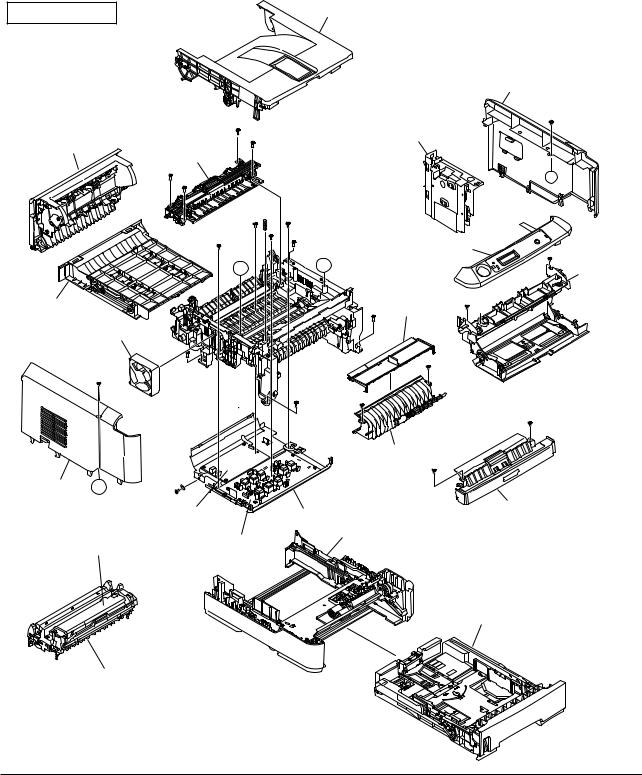
1.2 Printer Configuration
The printer main unit includes the following hardware parts.
•Electrophotographic processing part
•Paper feeding part
•Controller
•Operational part
•Power supply unit
Note! • Fuser-Assy has to be replaced by Assy unit.
• It is forbidden to disassemble Fuser-Assy or reuse the disassembled Fuser-Assy. The configuration of printer main unit is shown as diagram 1-2~1-4
B410d/B410dn
Rear-Cover-Assy
Fuser-Assy
A’
Duplex
Motor-Fan
Cover-Side-L A’ |
|
|
|
Low voltage |
|
|
power board |
|
Toner cartridge |
High voltage |
|
power board |
||
|
Image drum cartridge
Stacker-Cover-Assy
Cover-Side-R
CU board
A
|
OPE Cover-Assy |
A |
Manual-Assy |
|
Guide-Paper-R |
Guide-Paper-Duplex
Front-Guide-Assy
Plate-Base-PCB
Plate-Assy-Base
Paper cassette
Figure1-2
43984801TH Rev.1 |
/ |
Oki Data CONFIDENTIAL
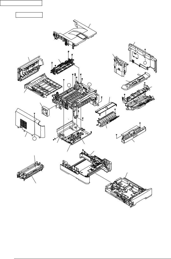
B430d/B430dn
Rear-Cover-Assy
Fuser-Assy
A’
Duplex
Motor-Fan
Cover-Side-L A’
Low voltage power board
Toner cartridge |
High voltage |
|
power board |
||
|
Image drum cartridge
1. CONFIGURATION
Stacker-Cover-Assy
Cover-Side-R
CU board
A
OPE Cover-Assy
A |
MPT-Assy |
|
|
|
Guide-Paper-R |
Guide-Paper-Duplex
Front-Guide-Assy
Plate-Base-PCB
Plate-Assy-Base
Paper cassette
Figure1-3
43984801TH Rev.1 |
/ |

Oki Data CONFIDENTIAL
B420dn
Rear-Cover-Assy
Fuser-Assy
A’
Duplex
Motor-Fan
Cover-Side-L A’
Low voltage power board
Toner cartridge |
High voltage |
power board |
Image drum cartridge
1. CONFIGURATION
Stacker-Cover-Assy
Cover-Side-R
CU board
A
OPE Cover-Assy
A |
MPT-Assy |
|
|
|
Guide-Paper-R |
Guide-Paper-Duplex
Front-Guide-Assy
Plate-Base-PCB
Plate-Assy-Base
Paper cassette
Figure1-4
43984801TH Rev.1 |
10 / |
Oki Data CONFIDENTIAL |
1. CONFIGURATION |
|
|
|
|
1.3 Optional Configuration
The options attached to the printer are as follows. These options can be ordered respectively for the printer main unit.
(1) Second tray unit
(2) Additionally installed memory (Domestic oriented printer only use 128MB.)
43984801TH Rev.1 |
11 / |
Oki Data CONFIDENTIAL |
|
1. CONFIGURATION |
|
|
|
|
|
|
1.4 Specification |
|
|
(1) Type |
|
Desktop |
|
||
(2) Dimension |
|
268mm (Height) x 369mm (Width) x 395 (Depth) |
|||
|
|
|
:B410d/B410dn/B430dn |
|
|
|
|
|
297mm (Height) x 369mm (Width) x 395mm (Depth) |
||
|
|
|
:B420dn |
|
|
(3) Weight |
|
Approx. 10.6kg ( Including printer main unit & consumables. |
|||
|
|
|
Options, Feeding quantity of paper are excluded.) |
||
(4) Development method |
Dray type – Element developing method |
||||
Exposure method |
LED Head method |
|
|||
(5) Paper type, thickness, Size |
|
||||
Recommended paper |
Normal paper………….Excellent white A4 |
||||
|
|
|
OHP Sheet…………….Sumitomo 3M CG3300 |
||
|
|
|
Label paper…………….Kokuyo LBP-A693 |
||
|
|
|
|
|
|
Category |
|
|
Size unit: mm (inch) |
Thickness |
|
|
|
|
|
|
|
|
|
A4 |
|
|
Weight 55~105kg(64~120g/m2) |
|
|
A5 |
|
|
For double-side printing, weight55~90kg |
|
|
|
|
|
(64~105g/m2) |
|
|
A6 |
|
|
|
|
|
B5 |
|
|
|
|
|
|
|
|
|
|
|
Letter |
|
|
|
|
|
|
|
|
|
Normal Paper |
|
Legal |
|
|
|
|
|
|
|
|
|
|
|
Legal |
|
|
|
|
|
|
|
|
|
|
|
Statement |
|
|
|
|
|
|
|
|
|
|
|
Executive |
|
Tray 1, Width 100~215.9, Length 210~355.6 |
|
|
|
|
|
|
|
|
|
Custom |
Width86~215.9 |
Tray 2, Width 148~215.9, Length 210~355.6 |
|
|
|
|
|||
|
|
Length 140~355.6 |
|
||
|
|
|
|
|
|
|
|
|
|
|
|
Postcard |
|
Postcard |
|
Postcard |
|
|
|
|
|
|
|
|
Return Postcard |
|
|
||
|
|
|
|
||
|
|
|
|
|
|
|
|
Envelope 1 (Chou #3) |
|
The envelope should be using 85g/m paper. The |
|
|
|
|
|
|
flap of the envelope Chou type should not be with |
|
|
|
|
|
fold, the flap of the envelope you should be clearly |
|
|
Envelope 2 (Chou #4) |
|
||
|
|
|
folded. |
||
|
|
|
|
|
|
|
|
Envelope 3 (You #4) |
|
||
|
|
|
|
||
|
|
|
|
|
|
|
|
|
|
|
The envelope should be using 24 lb. paper and |
Envelope |
|
|
|
|
the flap part of it should be clearly folded. |
|
|
|
|
|
|
|
|
|
|
|
|
|
|
|
|
|
|
|
|
|
|
|
|
|
|
|
|
|
|
|
|
|
|
|
|
|
|
Custom |
Width86~215.9 |
|
|
|
|
Length 140~355.6 |
|
||
|
|
|
|
|
|
|
|
|
|
|
|
Label Paper |
|
|
|
|
|
|
Letter |
|
|
|
|
|
|
|
|
|
|
|
|
|
|
|
|
OHP Sheet |
|
|
|
|
|
|
Letter |
|
|
|
|
|
|
|
|
|
|
|
|
|
|
|
|
Partial Printing |
|
|
|
|
Weight 55~105kg(64~120g/m2) |
Paper |
|
|
|
|
|
|
|
|
|
|
|
Paper for Color |
|
|
|
|
Weight 55~105kg(64~120g/m2) |
Printing |
|
|
|
|
|
|
|
|
|
|
|
|
|
|
|
|
|
43984801TH Rev.1 |
|
|
|
12 / |
|
Oki Data CONFIDENTIAL
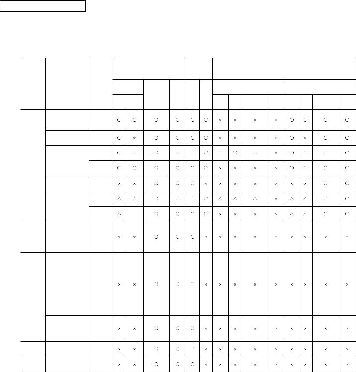
(6) Paper feeding method / Ejecting method
1. CONFIGURATION
○ : It is possible to use it.
× : It is not possible to use it.
: It is possible to use it by a part of size
|
|
|
|
|
|
Paper |
Paper |
|
|
|
|
|
|
|
|
|
|
|
|
|
ejecting |
|
Double-side print |
|
|
||||
|
|
|
|
|
feeding Method |
|
|
|
||||||
|
|
|
|
|
method |
|
|
|
|
|
|
|||
|
|
|
Thickness |
|
|
|
|
|
|
|
|
|
||
Type |
|
Size |
Paper |
|
|
|
|
Automatic |
|
|
Manual |
|
||
|
(Weight:Kg) |
|
|
|
|
|
|
|
||||||
|
|
|
cassette |
Multipurpose Manual |
Face |
Face |
double-side print *2 |
|
double-side print |
|
||||
|
|
|
|
|
Tray 2 |
Tray 2Multipurpose |
|
Tray 2 Multipurpose |
|
|||||
|
|
|
|
|
tray *1 |
up |
down |
|
|
|||||
|
|
|
|
Tray 1 |
*4 |
|
|
Tray 1 |
*4 |
tray*1 |
Manual Tray 1 |
*4 |
tray *1 |
Manual |
|
A5 *5 |
|
Weight |
|
|
|
|
|
|
|
|
|
|
|
|
B5 *5 |
|
|
|
|
|
|
|
|
|
|
|
|
|
|
Executive *5 |
55~105kg |
|
|
|
|
|
|
|
|
|
|
|
|
|
Statement *5 |
Weight |
|
|
|
|
|
|
|
|
|
|
|
|
|
|
|
55~105kg |
|
|
|
|
|
|
|
|
|
|
|
|
A4 |
|
Weight |
|
|
|
|
|
|
|
|
|
|
|
|
|
55~90kg |
|
|
|
|
|
|
|
|
|
|
|
|
|
Letter |
|
|
|
|
|
|
|
|
|
|
|
|
|
|
|
|
|
|
|
|
|
|
|
|
|
|
|
|
Normal |
Legal (13 inch) |
Weight |
|
|
|
|
|
|
|
|
|
|
|
|
paper |
Lega (14 inch) |
|
|
|
|
|
|
|
|
|
|
|
||
91~105kg |
|
|
|
|
|
|
|
|
|
|
|
|||
|
|
|
|
|
|
|
|
|
|
|
|
|
|
|
|
A6 *5 |
|
Weight |
|
|
|
|
|
|
|
|
|
|
|
|
|
|
55~105kg |
|
|
|
|
|
|
|
|
|
|
|
|
Custom *3 *5 |
Weight |
|
|
|
|
|
|
|
|
|
|
|
|
|
Width 86~215.9mm |
55~90kg |
|
|
|
|
|
|
|
|
|
|
|
|
|
|
|
|
|
|
|
|
|
|
|
|
|
||
|
Length |
Weight |
|
|
|
|
|
|
|
|
|
|
|
|
|
140~355.6mm |
|
|
|
|
|
|
|
|
|
|
|
||
|
91~105kg |
|
|
|
|
|
|
|
|
|
|
|
||
|
|
|
|
|
|
|
|
|
|
|
|
|
|
|
|
|
|
Postcard |
|
|
|
|
|
|
|
|
|
|
|
Postcard |
Postcard/ |
or less |
|
|
|
|
|
|
|
|
|
|
|
|
than |
|
|
|
|
|
|
|
|
|
|
|
|||
*5 |
Return postcard |
|
|
|
|
|
|
|
|
|
|
|
||
|
|
|
weight |
|
|
|
|
|
|
|
|
|
|
|
|
|
|
135kg |
|
|
|
|
|
|
|
|
|
|
|
|
Envelope1 (CHOU |
|
|
|
|
|
|
|
|
|
|
|
|
|
|
3) |
|
|
|
|
|
|
|
|
|
|
|
|
|
|
Envelope2 (CHOU |
|
|
|
|
|
|
|
|
|
|
|
|
|
|
4) |
|
|
|
|
|
|
|
|
|
|
|
|
|
|
Envelope3 (YOU 4) |
*6 |
|
|
|
|
|
|
|
|
|
|
|
|
|
Com-9 |
|
|
|
|
|
|
|
|
|
|
|
||
|
Com-10 |
|
|
|
|
|
|
|
|
|
|
|
|
|
Envelope |
DL |
|
|
|
|
|
|
|
|
|
|
|
|
|
*5 |
C5 |
|
|
|
|
|
|
|
|
|
|
|
|
|
|
C6 |
|
|
|
|
|
|
|
|
|
|
|
|
|
|
Monarch |
|
|
|
|
|
|
|
|
|
|
|
|
|
|
Custom |
|
|
|
|
|
|
|
|
|
|
|
|
|
|
Width 86~215.9mm |
*6 |
|
|
|
|
|
|
|
|
|
|
|
|
|
Length |
|
|
|
|
|
|
|
|
|
|
|
|
|
|
140~355.6mm |
|
|
|
|
|
|
|
|
|
|
|
|
|
Label |
A4/Letter |
0.1~ |
|
|
|
|
|
|
|
|
|
|
|
|
paper |
0.5mm |
|
|
|
|
|
|
|
|
|
|
|
||
|
|
|
|
|
|
|
|
|
|
|
|
|
||
OHP |
A4/Letter |
0.1~ |
|
|
|
|
|
|
|
|
|
|
|
|
0.5mm |
|
|
|
|
|
|
|
|
|
|
|
|||
|
|
|
|
|
|
|
|
|
|
|
|
|
|
|
|
*1: Multipurpose tray can be used for B420dn/B430dn. |
|
|
|
|
|
|
|
|
|||||
|
*2: Face-up paper ejecting is not available at automatic double-side printing. |
|
|
|
|
|
|
|||||||
|
*3: Tray 1 is as width 100~21539mm, length 210~355.6mm. Tray 2 is as width 148~215.99mm, length 210~355.6mm. |
|
||||||||||||
|
*4: |
Tray 2 (The second tray unit) is for option. |
|
|
|
|
|
|
|
|
||||
*5: In case to set up the paper size for A5, A6, Postcard, Envelope, if the width of B5, Executive, Statement, Normal paper is less than 200mm, also if thick paper or thicker paper has been set up for the paper thickness, the printing speed changes to be slowly.
*6: • Envelope CHOU should be made by the paper or basis weight of 85g/m2 and without any fold on the flap part.
•Envelope YOU should be made by the paper of basis weight of 85g/m2 and with clear fold on the flap part.
•Com-9, Com-10, Monarch, C5, C6, and DL should be the envelope using 24lb paper and with clear fold on the flap part.
(7) Printing speed |
Continuous printing |
: Maximum 28 piece/second (A4, At copy mode, First try) |
|
|
For Envelope • Postcard, if to enhance the printing quality, the |
|
|
printing speed changes to be decreased. |
|
|
For the resolution degree of 600 x 2400, if to enhance the |
|
|
printing quality, the printing speed changes to be decreased. |
|
Warm up time |
: Approx. 25 second (25°C, 100V) |
|
|
|
43984801TH Rev.1 |
|
13 / |

Oki Data CONFIDENTIAL |
1. CONFIGURATION |
|
|
|
|
(8) |
Paper feeding method |
Automatic feeding |
(9) |
Paper ejecting method |
Face down (Rear ejecting) / Face up (Front ejecting) |
(10) |
Resolution (Max.) |
2400 × 600 dots / inch (B410d/B410dn/B420dn) |
|
|
1200 × 1200 dots / inch (B430d/B430dn) |
(11) |
Input electricity |
AC100V ± 10V, 50/60Hz ± 1Hz(B410dn/B430dn) |
(12) |
Electricity consumption |
Up and running: Maximum 800W, Average 450W (25°C) |
|
|
Ready and waiting: Average 70W (25°C) |
|
|
Power-saving mode: (Without option) Under 6W |
|
|
|
(With option) |
Maximum 7W |
(13)Temperature and Humidity |
|
|
||
|
|
|
|
|
|
|
Tenperature |
Humidity |
|
|
|
|
|
|
|
Up and |
10~32 |
20~80%RH (Relative Humidity) No condensation. |
|
|
running |
|
However, Maximum temperature of wet ball should |
|
|
|
|
be 25°C. |
|
|
|
|
|
|
|
Power switch |
0~43 |
10~90%RH (Relative Temperature) No |
|
|
off |
|
condensation. However, Maximum temperature of |
|
|
|
|
wet ball should be 26.8°C. |
|
|
|
|
|
|
|
Keeping |
-10~43 |
10~90%RH (Relative Humidity) No condensation. |
|
|
|
|
However, Maximum temperature of wet ball should |
|
|
|
|
be 26.8°C. |
|
|
|
|
|
|
Temperature (°C)
|
32 |
|
|
|
|
|
|
|
|
|
|
|
|
|
|
|
|
|
|
|
28 |
|
|
|
|
|
|
Up and running |
|
|
|
|
|
|
|
|
|||
|
|
|
|
|
|
|
|
||
|
10 |
|
|
|
|
|
|
|
|
|
|
|
|
|
|
|
|
|
|
|
|
|
|
|
|
|
|
|
|
|
|
|
|
|
|
|
|
Relative humidity (%) |
|
|
|
|
20 |
80 |
|||||
|
|
|
|
|
|||||
(14) Operating noise |
In Printing |
|
: Rage A based on JIS Z9831, Average below 53dBA for SLOW. |
||||||
|
Ready and waiting : Rage A based on JIS Z9831, Average below 53dBA for SLOW. |
||||||||
|
At power save |
|
: No sound (Background level) |
||||||
(15) Consumables |
Toner cartridge |
|
: Approx. 3,500 piece /Approx. 7,000 piece/Approx. 10,000 |
||||||
|
|
|
|
|
|
piece(A4 ISO/IEC 19752 Continuous printing as |
|||
|
|
|
|
|
printing paten. But, except the 1st Toner cartridge) |
||||
|
Image drum |
|
: Approx. 25,000 piece (Continuously single-side printing of A4) |
||||||
|
Cartridge |
|
: Approx. 20,000 piece (Single-side 3 pages/job) At Power save off. |
||||||
|
|
|
|
|
Approx. 12,000 piece (Single-side 1 page/job) At Power save off. |
||||
Approx. 7,000 piece (Single-side 1 page/job) At Power save on (Minimum value).
43984801TH Rev.1 |
14 / |
Oki Data CONFIDENTIAL |
1. CONFIGURATION |
|
|
|
|
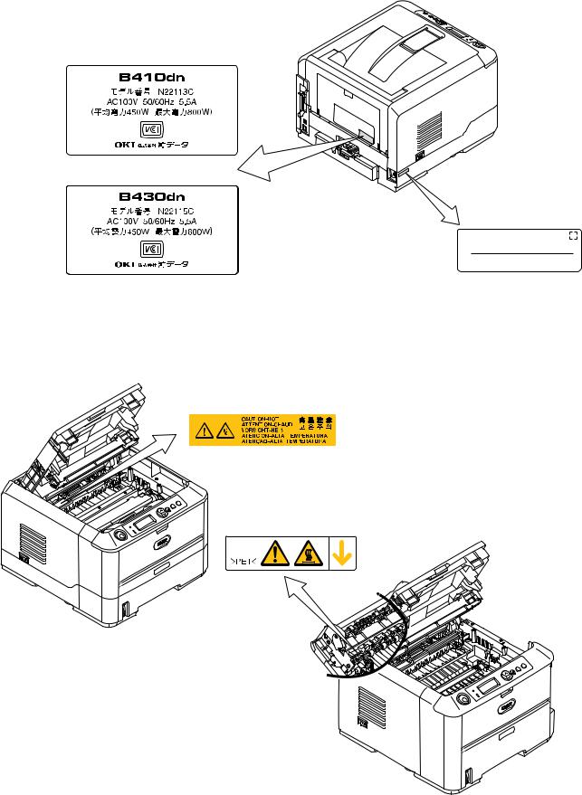
1.5 Printing display
1.5.1 VCCI label, Serial No. label
The VCCI label and Serial No. label have been attached on the specified part of printer as shows below.
B410dn
B430dn
Serial No.
Made In China
1.5.2 Warning label
Warning label has been attached on the part of printer that may cause injury to the operator. Maintenance must be performed following the indication of the warning label.
|
|
|
|
|
|
|
|
|
|
|
|
|
|
|
|
|
|
|
|
|
|
|
|
|
|
|
|
|
|
|
|
|
|
|
|
|
|
|
|
|
|
|
|
|
|
|
|
|
|
|
|
|
|
|
|
|
|
|
|
|
|
|
43984801TH Rev.1 |
15 / |
|||||
Oki Data CONFIDENTIAL |
1. CONFIGURATION |
|
|
|
|
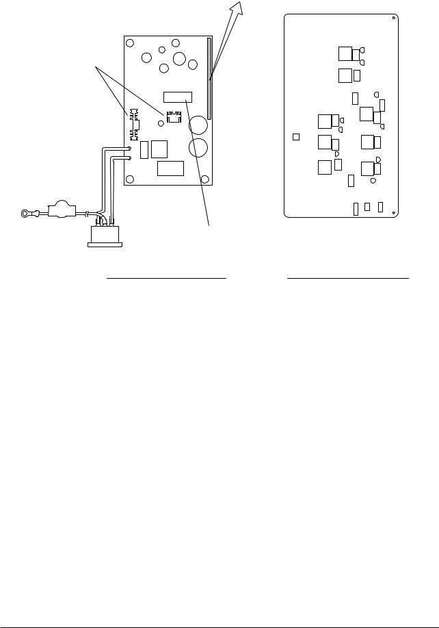
1.5.3 Warning / Caution display
The following warning / caution are displayed on the electrical power / sensor board.
Warning / Caution content record
Heat sink
Transformer |
|
Low voltage power board |
High voltage power board |
Note! • There is a risk of electric shock in the middle of the heat sink and transformer. Be sure to check before touch it.
• It may happen that the electricity has still left on the electrical circuit even after the fuse opened.
43984801TH Rev.1 |
16 / |

Oki Data CONFIDENTIAL |
2. Operational explanation |
|
|
|
|
2.Operational explanation
2.1Electrophotographic process mechanism
(1)Electrophotographic process
The following describes the overview of electrophotographic process.
1.Charging
Equally charge the surface of image drum by applying negative voltage to the charged roller due to negative charge.
2.Exposure
The light from LED Head is exposed on the negative-charged surface of image drum. The surface electrical potential of the exposed part of image drum surface becomes lower. Then forms electrostatic latent image.
3. Development
Negative-charged toner is attracted to the electrostatic latent image due to electrostatic while touching the image drum. Then forms viewable image.
4.Transfer
Overlap paper on the surface of OPC drum, from the backside of paper transfer toner image to the paper by applying electrical charge by transfer roller.
5.Drum cleaning
The remaining toner on the image drum that is not transferred is made to be equable by cleaning roller. And is temporarily attracted to the cleaning roller due to electrostatic.
6. Fusing
The toner image that is transferred to paper is fused on paper by heat and pressure.
43984801TH Rev.1 |
17 / |
Oki Data CONFIDENTIAL |
2. Operational explanation |
|
|
|
|
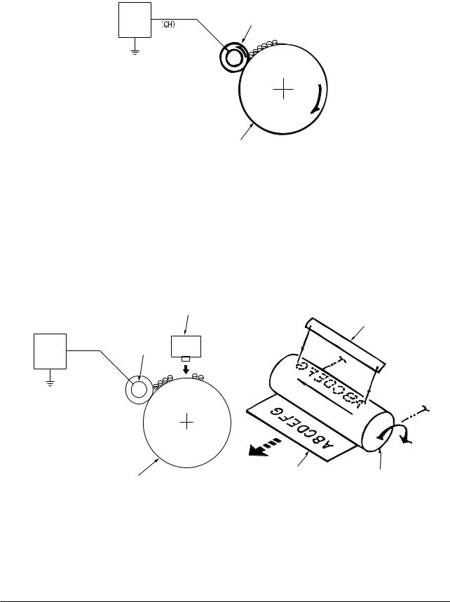
1.Charging
Charge the image drum surface by applying voltage to the charged roller that contacts the image drum surface.
Power |
Charged roller |
Image drum
2. Exposure
The light emitting from the LED Head will be exposed to the negative charged image drum. When the surface electric potential of exposed part of the image drum goes to decrease, the electrostatic latent image complying with image signal is formed.
Image drum is coated by basic layer (UL), charge generating layer (CGL), charge transferring layer (CTL) on the basic material aluminum. The thickness of the organic light sensor (OPC) that is consisted by CTL and CGL is approximate 20µm.
LED head
LED head
Power |
Charged roller |
|
Image drum |
Paper |
Image drum |
|
||
|
|
43984801TH Rev.1 |
18 / |

Oki Data CONFIDENTIAL |
2. Operational explanation |
|
|
|
|
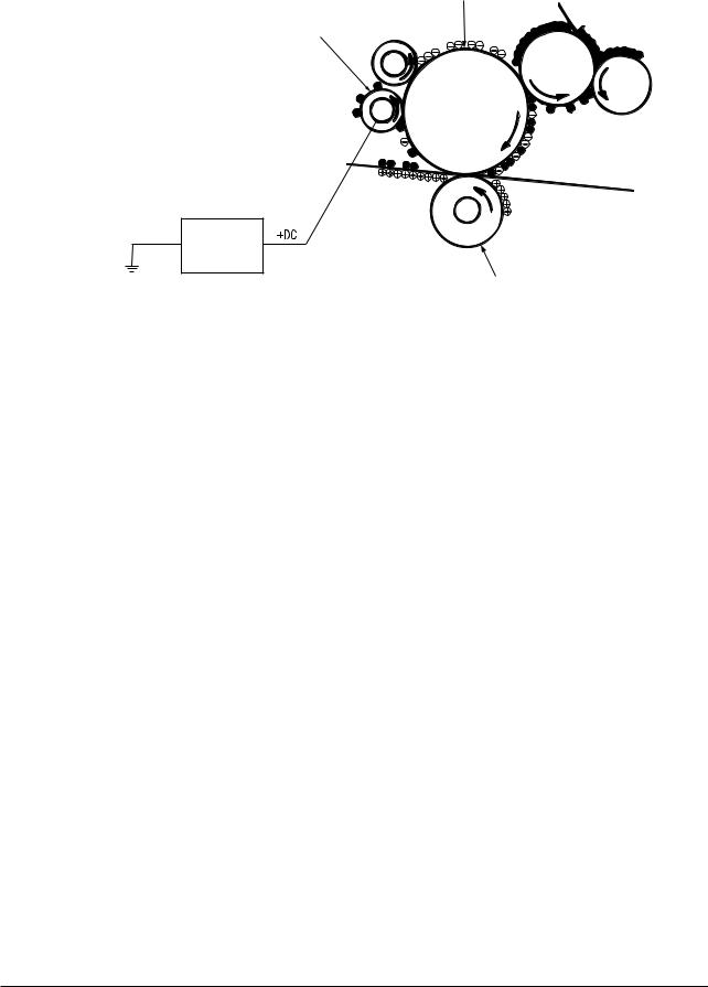
3. Image development
Toner is attracted to the electrostatic latent image on the image drum surface, then the electrostatic latent image changes to toner image.
1As the roller on the supply spot of toner rotates while scrubbing the image-developing roller, fiction electricity occurs between the image developing roller and toner; toner is attracted to the image-developing roller.
Image developing plate
Charged roller
Toner supply roller
Image developing roller
Image drum
2.The toner that has been attracted to the image-developing roller is dropped down to the developing plate to make a thin toner film on the image developing roller side.
3The toner is attracted by the exposed part (Low electrical potential part) of the image drum when the image drum contact the image developing roller, so as to see the electrostatic latent image.
43984801TH Rev.1 |
19 / |

Oki Data CONFIDENTIAL |
2. Operational explanation |
|
|
|
|
Note! The necessary bypass voltage in image processing is impressed on the toner feeding roller
and image developing roller as show below.
While the cover is closed it will be connected and bias will be applied.
 Toner feeding roller
Image developing roller
Basic material
Image drum
43984801TH Rev.1 |
20 / |
Oki Data CONFIDENTIAL |
2. Operational explanation |
|
|
|
|
4.Transfer
The transfer roller, which is from conductive sponge material, is created to meet intimate attachment of image drum roller surface and feeding paper. The feeding paper is set up on the surface of image drum. Plus charge, which is the converse polarity with toner polarity, is applied from the backside of the paper.
As high plus voltage is applied to transfer roller from the power supply, the plus charge on the transfer roller surface is induced and transferred to the paper while the paper contact the transfer roller. The negative charged toner, which has been attracted to the image drum surface, is transferred to the surface of feeding paper by the plus charge of the backside of the paper.
Image drum
Paper
Transfer roller
Power
43984801TH Rev.1 |
21 / |
Oki Data CONFIDENTIAL |
2. Operational explanation |
|
|
|
|
5.Drum cleaning
1Cleaning
After the completion of transferring, the remaining toner on the image drum is temporarily attracted by the electrostatic and the image drum surface is cleaned.
Image drum
Cleaning roller
Power supply
Transferring roller
2 Roller cleaning
In the following case, there is a need of cleaning the charged roller, transfer roller, and cleaning roller.
•Warming up as switching on the power supply
•Warming up after open-close of the cover
•In case of termination of printing operation
•By periodically change the bias voltage that is implied to each roller during continuous printing, transfer the attached toner from roller to image drum and then return it to developing device.
43984801TH Rev.1 |
22 / |

Oki Data CONFIDENTIAL |
2. Operational explanation |
|
|
|
|
6. Fusing
After the termination of transfer the unsettled toner image is settled to paper by heat and pressure while passing between Heat roller and Back up roller. Heat roller is Teflon coated and is mounted by heater that can generate heat (Halogen lamp).
The thermistor that contacts the Heat roller adjusts the Heat roller temperature to the temperature specified by the menu complying with the paper width. For safety the thermostat shuts off the voltage supply to the Heater by opening the thermostat in the case of abnormally temperature increasing.
The back up roller is held by the pressure springs on each terminal due to the pressure applied.
Thermostat
Heat roller
Separating clutch
Heater
Thermistor
Feeding paper
Backup roller
Pressuring spring
43984801TH Rev.1 |
23 / |
Oki Data CONFIDENTIAL |
2. Operational explanation |
|
|
|
|
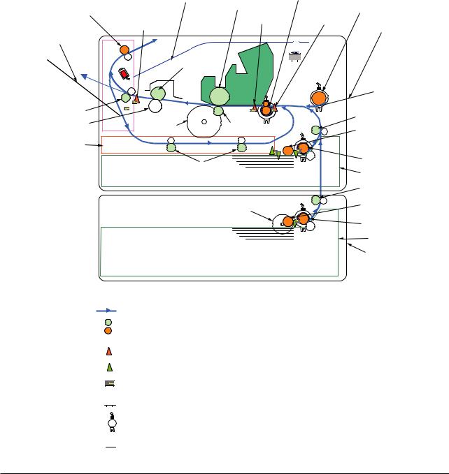
2.2 Printing process
The paper fed from Tray 1 and Tray 2 is conveyed by feeding roller, conveying roller, and resist roller. When feeding paper is from MPT, it is conveyed by MPT, feeding roller, and resist roller. After that the feeding paper that is conveyed by image drum and the nip part of transfer roller forms toner image on the paper through electrophotographic process. And then, the toner on the paper is fused by the heat and pressure as the fuser unit passing through. The paper that fused the toner image is ejected from the face down stacker of the ejecting roller. In the case of face up ejecting, it needs to open the backside cover and install face up stacker. (It is unavailable for duplex printing while it is face up ejecting.)
The above is about the operations at simplex printing, yet the below explains the operations at duplex printing. While duplex printing, the paper, which firstly passed through the fuser unit after the backside printing, is conveyed to the inward of Duplex Unit, by the reverse operation of the second ejecting roller that is a certain time after removing the first ejecting roller of the paper rear side. Paper, is conveyed by conveying roller of Duplex Unit, and then merges to the same route with the feeding paper that is from the tray. Onwards, it is the same with the simplex printing operation by the feeding paper from tray.
|
Face down stacker |
Resist roller |
|
|
The 2nd ejecting roller |
Image drum |
Entrance |
MPT feeding roller |
|
Ejecting |
Writing out |
|
||
|
sensor lever |
sensor lever |
||
|
sensor lever |
|
Multipurpose tray |
|
|
|
|
||
Face up stacker |
|
|
|
|
|
|
Heat roller |
|
|
The 1st ejecting roller |
|
|
Conveying roller |
|
Backup roller |
|
|
||
DC motor |
Transferring roller |
Pick up roller |
||
|
||||
Duplex unit |
|
|
|
|
|
Conveying roller |
Feeding roller |
||
|
Tray 1 |
|||
|
|
|
||
|
|
|
Conveying roller |
|
|
|
Pulse motor |
Pick up roller |
|
|
|
|
||
|
|
|
Feeding roller |
|
|
|
|
Tray 2 |
|
|
|
|
2nd tray unit (option) |
|
Paper conveying route
Driving roller (Continuous rotation)
Driving roller (Control rotation)
 Driving roller
Paper level indicator lever
Indicating lever
Photo sensor

 Micro switch
 Magnetic clutch


 Solenoid
43984801TH Rev.1 |
24 / |

Oki Data CONFIDENTIAL |
2. Operational explanation |
|
|
|
|
(1)Paper feeding from Tray 1
1.As DC motor rotating (Counterclockwise rotation), if set the paper feeding clutch as ON, as the paper feeding roller and pick up roller rotating, the paper that is inside the tray is conveyed.
2.The paper is conveyed by the conveying roller. After the entrance sensor level set to be ON, it bumps into the stopping resist roller, a certain more amount of paper is conveyed. (This corrects the paper skew.)
3.If set the resist clutch as ON, the paper is conveyed by resist roller.
Resist roller |
Resist clutch |
|
Writing out sensor lever |
||
Entrance sensor lever |
||
|
Conveying roller
DC motor
(Counterclockwise rotation) Pick up roller 
Paper feeding roller
Paper
Paper feeding clutch
(2)Paper feeding from Multipurpose tray (MPT)(B420dn, B430d, B430dn)
1.As DC motor rotating (Counterclockwise rotation), if set paper feeding clutch as ON the MPT paper feeding roller starts to rotate, the paper in the tray is conveyed.
2.After setting the entrance sensor lever as ON, the paper bumps into the stopping resist roller, a certain more amount of paper is conveyed. (This corrects the skew of paper.)
3.If set the resist clutch as ON, the paper is conveyed by resist roller.
Entrance sensor lever |
||
Resist clutch |
Paper feeding clutch |
|
Resist roller |
MPT paper feeding roller |
|
Writing out sensor lever |
||
|
||
|
Paper |
|
DV motor (Counterclockwise rotation)
43984801TH Rev.1 |
25 / |

Oki Data CONFIDENTIAL |
2. Operational explanation |
|
|
|
|
(3)Fuser unit and paper ejecting
1.The fuser unit and eject roller is
2.Simultaneously the eject roller rotates, and then the paper is ejected.
Eject roller 
Planet gear
Paper route
Fuser unit
Heat roller
Solenoid
Eject roller
DC motor (Counterclockwise rotation)
43984801TH Rev.1 |
26 / |

Oki Data CONFIDENTIAL |
2. Operational explanation |
|
|
|
|
(4)Paper reversing and paper multi-feeding
1.TRemoving the first eject roller at the rear part of paper and set the solenoid as ON for a while, then the planet gear starts to move, the second eject roller starts inverse rotating (Counterclockwise rotation).
2.By the inverse rotation of the second eject roller the paper is inversely rotated and conveyed to Duplex.
3.Paper is conveyed by Duplex conveying roller.
4.After setting the entrance sensor lever as ON, paper bumps into the stopped resist roller, still a certain more amount of paper is conveyed. (This corrects the skew of paper.).
5.If set the Resist clutch as ON, paper is conveyed by Resist roller.
[ Normal rotation ] |
|
|
|
The 2nd ejecting |
|
|
|
roller |
|
|
|
Planet gear |
|
|
|
Fuser unit |
DC motor |
|
|
(Counterclockwise rotation) |
|||
Heat roller |
|||
|
Writing out |
Resist roller |
|
Solenoid |
sensor lever |
Resist clutch |
|
Resist Entrance |
|||
(OFF) |
|
||
|
sensor lever |
||
|
|
||
The 1st ejecting roller |
|
|
|
Duplex conveying roller Belt |
Duplex conveying roller |
|||
[ Inverse rotation ] |
|
|
|
|
The 2nd ejecting |
|
|
|
|
roller |
|
|
|
|
Planet gearFuser unit |
DC motor |
|
|
|
(Counterclockwise rotation) |
|
|||
Heat roller |
|
|
|
|
|
Writing out |
Resist roller |
|
|
|
|
Resist clutch |
||
Solenoid |
sensor lever |
|||
Resist Entrance |
||||
(ON) |
|
|
||
|
|
sensor lever |
||
|
|
|
||
The 1st ejecting roller |
|
|
|
|
|
|
|
|
|
|
|
|
|
|
|
|
|
|
|
|
|
|
Duplex conveying roller Belt |
Duplex conveying roller |
|||||||
43984801TH Rev.1 |
27 / |
Oki Data CONFIDENTIAL |
2. Operational explanation |
|
|
|
|
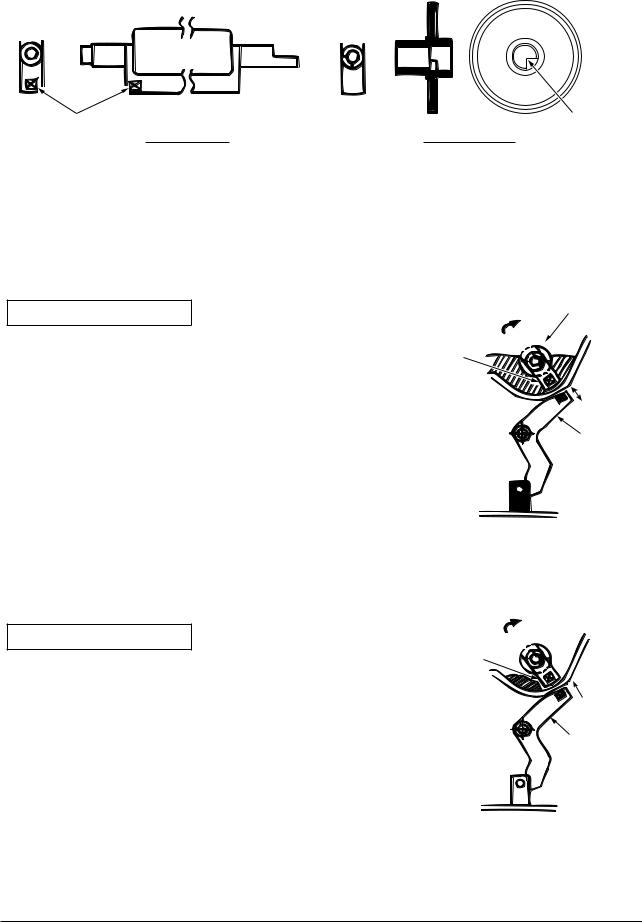
2.3 Toner entrance detection
•Equipment
Toner entrance detecting equipment consists the agitating gear that agitating the agitating bar at a certain speed and magnet that is on the agitating bar.
Magnet |
Crack part |
Agitating bar |
Agitating gear |
•Operation
Detecting the toner low by monitoring the congruous time intervals between the magnet that is set on the sensor plate and the magnet attached on the agitating bar,
Operation in toner full status
•The crack part of agitating gear meshing with the projection portion of agitating bar, the agitating bar rotates in accordance with the rotating of gear.
•Even after the magnet part of the agitating Bar reaches the highest position, it still rotates at the same speed by the pressure of the agitating gear due to the toner resistance.
Operation in toner low status
•When the magnet part of the agitating bar reaches the highest position, because there is no resistance from toner, the agitating bar drops earlier than the gear by the gravity itself, and stops by that status.
For this reason, the time that the magnet of agitating Bar magnetic attracts the magnet of sensor plate becomes longer. The toner low status can be inspected by monitoring this time.
Agitating gear
Agitating bar
Sensor plate
Toner sensor 

Agitating bar
Sensor plate
43984801TH Rev.1 |
28 / |

Oki Data CONFIDENTIAL |
2. Operational explanation |
|
|
|
|
Toner full status
Toner low status |
|
|
t1 t2 |
t1,t2: Magnet attracting time |
|||||||
|
|
|
|
|
|
|
|
|
|
|
|
|
|
|
|
|
|
|
|
|
|
|
|
|
|
|
|
|
|
|
|
|
|
|
|
|
|
|
|
|
|
|
|
|
|
|
|
|
|
|
|
|
|
|
|
|
|
|
|
|
|
|
|
|
|
|
|
|
|
|
|
|
|
|
|
|
|
|
|
|
|
|
|
•Toner sensor alarm actuates if there is not any change on toner sensor.
•Toner sensor is not monitored while main (drum) motor is stopping.
43984801TH Rev.1 |
29 / |
Oki Data CONFIDENTIAL |
3. Parts replacement |
|
|
|
|
3. Parts replacement
This section explains the replacement procedure of part, assembly, and unit in the working place. Disassembling procedure relating to reassembling is conducted conversely.
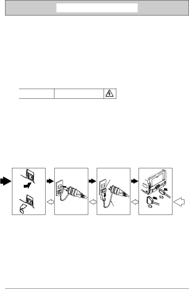
3.1Preparation for parts replacement
(1)Be sure to unplug the AC cord and interface cable before starting to replace parts.
(a)Unplugging the AC cord by the following procedures.
i)Shut off the power switch of the printer. (  )
)
ii)Unplug the AC insert plug of AC cord from the AC socket.
iii)Remove the earth wire from AC socket.
iv)Unplug the AC cord and interface cable from printer.

 Warning Risk of Electric Shock
There is a risk of electric shock during replacement of the low voltage power supply.
Use insulating gloves or avoid direct contact with any conducting part of the power supply, and caution should be exercised during replacement.
The capacitor may take one minute to complete discharge after the AC cord is unplugged. Also, there is a possibility that the capacitor doesn’t discharge because of a breakage of the PCB, etc., so remember the possibility of electric shock to avoid electric shock.
(b)Reconnecting the printer by the following procedures.
i)Connect the AC cord and interface cable to the printer.
ii)Connect earth wire to the AC socket.
iii)Connect the AC insert plug to the AC socket.
iv)Turn on the power switch of the printer. ( I )
Shutting off
Earth terminal
OFF
Reconnecting
Earth cable
ON
(2)Do not disassemble the printer in the case of normal operation.
(3)Do not disengage the part that there is not any necessary to touch. Disassembly should be the minimum.
(4)Be sure to use the specified maintenance tools.
(5)Be sure to temporarily install the small part such as screw, collar, and so on at its original position during disassembling because it is easy to be lost.
(6)Do not use the gloves that is easy to occur electrostatic while dealing with IC such as micro-sensor, ROM, RAM, etc. and PCB.
(7)Do not put the print circuit board on the equipment or on the floor directly.
(8)Do not put the Print Circuit Board on the printer of on the floor directly.
43984801TH Rev.1 |
30 / |
 Loading...